FLIR DM6 Series User manual

USER MANUAL
True RMS Digital MultiMeter Series
Models DM62, DM64, and DM66

FLIR DM6x USER MANUAL Document Identifier: DM6x-en-US_AA
2
Table of Contents
1. ADVISORIES 4
1.1 Copyright 4
1.2 Quality Assurance 4
1.3 Documentation 4
1.4 Disposal of Electronic Waste 4
2. SAFETY 5
3. INTRODUCTION 7
4. METER AND DISPLAY DESCRIPTIONS 8
4.1 Front and Back Meter Descriptions 8
4.2 Rotary Function Selector 9
4.3 Control Buttons 9
4.4 Display Description 10
5. BASIC OPERATION AND FEATURES 11
5.1 Powering the Meter 11
5.2 Intelligent Auto Power OFF (APO) 11
5.3 LCD Backlight 11
5.4 Auto/Manual Range Mode 11
5.5 True RMS Response 11
5.6 Crest Factor 11
5.7 Out-of-range Warning (O.L) 11
5.8 Data Hold 12
5.9 Relative Zero Mode 12
5.10 VFD Mode (Low Pass Filter) Models DM64/DM66 only 12
5.11 MAX-MIN-AVG Record Mode 12
5.12 Test Lead Input Warning 12
5.13 Auto Voltage AC/DC Detection in ‘Lo Z’ mode (DM64/DM66 only) 12
6. MEASUREMENTS 13
6.1 AC/DC Voltage Measurements (VFD and Frequency on DM64/DM66) 13
6.2 Low Impedance (Lo Z) Auto-Voltage Measurements (DM64/66 only) 14
6.3 Line Frequency Measurements (DM64/DM66 only) 15
6.4 Resistance and Continuity Measurements 16
6.5 Capacitance (DM64/DM66) and Diode Measurements 17
6.6 AC/DC mV and Temperature (DM64/DM66) Measurements 19

FLIR DM6x USER MANUAL Document Identifier: DM6x-en-US_AA
3
6.7 A, mA, A Current Measurements with Frequency (DM64/DM66) 21
6.8 NCV (Non-Contact Voltage) Detection 22
7. MAINTENANCE 23
7.1 Cleaning and Storage 23
7.2 Battery and Fuse Replacement 23
7.3 Disposal of Electronic Waste 23
8. SPECIFICATIONS 24
8.1 General specifications 24
8.2 Electrical Specifications 25
9. TECHNICAL SUPPORT 29
10. THREE-YEAR LIMITED WARRANTY 30

FLIR DM6x USER MANUAL Document Identifier: DM6x-en-US_AA
4
1. Advisories
1.1 Copyright
© 2018, FLIR Systems, Inc. All rights reserved worldwide. No parts of the software
including source code may be reproduced, transmitted, transcribed or translated into
any language or computer language in any form or by any means, electronic, magnetic,
optical, manual or otherwise, without the prior written permission of FLIR Systems.
The documentation must not, in whole or part, be copied, photocopied, reproduced,
translated or transmitted to any electronic medium or machine readable form without
prior consent, in writing, from FLIR Systems.
Names and marks appearing on the products herein are either registered trademarks or
trademarks of FLIR Systems and/or its subsidiaries. All other trademarks, trade names or
company names referenced herein are used for identification only and are the property
of their respective owners.
1.2 Quality Assurance
The Quality Management System under which these products are developed and
manufactured has been certified in accordance with the ISO 9001 standard.
FLIR Systems is committed to a policy of continuous development; therefore, we reserve
the right to make changes and improvements on any of the products without prior
notice.
1.3 Documentation
To access the latest manuals and notifications, go to the Download tab at:
http://support.flir.com. It only takes a few minutes to register online. In the download
area you will also find the latest releases of manuals for our other products, as well as
manuals for our historical and obsolete products.
1.4 Disposal of Electronic Waste
As with most electronic products, this equipment must be disposed of in an
environmentally friendly way, and in accordance with existing regulations for
electronic waste.
Please contact your FLIR Systems representative for more details.

FLIR DM6x USER MANUAL Document Identifier: DM6x-en-US_AA
5
2. Safety
Safety Notes
This manual contains information and warnings that must be followed for operating the
meter safely and maintaining the meter in a safe operating condition. If the meter is used
in a manner not specified by the manufacturer, the protection provided by the meter
may be impaired.
Terms in this manual
WARNING Identifies conditions and actions that could result in serious injury or even
death to the user.
CAUTION Identifies conditions and actions that could cause damage or malfunction in
the instrument.
WARNING
To reduce the risk of fire or electric shock, do not expose this product to rain or moisture.
The meter is intended only for indoor use.
Keep your hands/fingers behind the hand/finger barriers (of the meter and the test
probe assembly, where applicable) that indicate the limits of safe access of the hand-held
parts during measurements. Inspect lead wires, connectors, and probes for damaged
insulation or exposed metal before using the meter. If any defects are found, replace
them immediately. Only use the probe assembly provided with the meter or a UL Listed
Probe Assembly to the same meter ratings or better.
IEC 61010-031 requires exposed conductive test probe tips to be ≤4mm for CAT III & CAT
IV ratings. Refer to the category markings on your probe assemblies as well as on the
add-on accessories (like detachable Caps or Alligator Clips), if any, for applicable rating
changes.
Observe proper safety precautions when working with voltages above 33 Vrms, 46.7
Vpeak or 70 VDC. These voltage levels pose a potential shock hazard to the user. Before
and after hazardous voltage measurements, check the voltage function on a known
source such as line voltage to determine proper meter functioning.
CAUTION
Disconnect the test leads from the test points before changing functions.

FLIR DM6x USER MANUAL Document Identifier: DM6x-en-US_AA
6
International Electrical Symbols
Marking of Electrical and Electronic Equipment (EEE). Do not dispose of this
product as unsorted municipal waste. Contact a qualified recycler
Caution! Refer to the explanation in this Manual
Caution! Possibility of electric shock
Earth (Ground)
Meter protected throughout by Double Insulation or Reinforced insulation
Fuse
Direct Current (DC)
Alternating Current (AC)
3Three-phase Alternating Current
Measurement Categories
Measurement Category IV is applicable to test and measuring circuits connected at
the source of the building’s low-voltage MAINS installation. Examples are
measurements on devices installed before the main fuse or circuit breaker in the
building installation.
Measurement Category III is applicable to test and measuring circuits connected to
the distribution part of the building’s low-voltage MAINS installation. Examples are
measurements on distribution boards (including secondary meters), circuit-breakers,
wiring, including cables, bus-bars, junction boxes, switches, and socket-outlets in the
fixed installation, and equipment for industrial use and some other equipment such as
stationary motors with permanent connection to the fixed installation.
CENELEC DIRECTIVES
The instruments conform to CENELEC Low-voltage directive 2014/35/EC,
Electromagnetic compatibility directive 2014/30/EU and RoHS directive 2011/65/EU.

FLIR DM6x USER MANUAL Document Identifier: DM6x-en-US_AA
7
3. Introduction
Thank you for selecting the FLIR DM6x Digital Multimeter. This meter can measure up to
600V and 10A AC/DC. This device is shipped fully tested and calibrated and, with proper
use, will provide years of reliable service.
Features
6000 Count (3-5/6 digits) backlit LCD with 5 reading per second update rate
Auto Power OFF
Measures ACV, DCV, Resistance, Continuity, Capacitance*, Diode, DCA, ACA,
Temperature*, line Frequency*, non-contact Voltage (NCV)
True RMS responding
Auto AC/DC detection for voltage measurements*
Lo Z (low impedance) for ghost voltage protection*
Auto ranging
VFD feature (low pass filter for AC voltage measurements)*
MIN-MAX-AVG Reading Memory
Relative Zero mode
Equipped with test leads, batteries, printed Quick Start (full User Manual available
on FLIR website http://support.flir.com), and type K thermocouple*
Optional accessories: Banana plug to type-K socket plug adaptor*, magnetic hanger,
and carrying pouch
*Applies to models DM64 and DM66 only

FLIR DM6x USER MANUAL Document Identifier: DM6x-en-US_AA
8
4. Meter and Display Descriptions
4.1 Front and Back Meter Descriptions
1. Non-Contact Voltage Detector
2. LCD
3. Control buttons
4. Rotary Selector Switch
5. ‘A’ Current input terminal
6. ‘uA, mA’ Current input terminal
7. COM (negative -) input terminal
8. Positive (+) input terminal for all inputs except Current
9. Battery compartment lock and fuse access
10. Test Lead holders
11. Battery compartment and fuse access
12. Tilt stand
Fig. 4-1 Front and Back Views (DM66)

FLIR DM6x USER MANUAL Document Identifier: DM6x-en-US_AA
9
4.2 Rotary Function Selector
Lo Z (low impedance) mode with Auto ACV/DCV detection (DM64/DM6)
Meter power off
AC/DC Voltage and VFD (low pass filter) modes (VFD available in models
DM64/DM66 only)
Resistance and Continuity measurements
Temperature (DM64 and DM66 only) and AC/DC milli-volt
measurements
Capacitance (DM64 and DM66 only) and Diode measurements
AC/DC Amp and milli-amp current measurements
AC/DC micro-amp current measurements
4.3 Control Buttons
Long press to switch LCD Backlight ON/OFF
Mode select button. For rotary switch positions with more than one
function, use this button to select the desired function
Short press to select MANUAL mode and to change ranges, long press to
return to AUTO. Also used to select sensitivity in NCV mode and trigger
level for line frequency measurements (DM64/DM66)
Short press to access MIN-MAX-AVG Record mode. Short press to step
through MIN-MAX-AVG readings. Long press to exit
Long press the Relative/Zero button to switch the mode ON/OFF. When
switched on, the displayed reading is stored as reference/offset value
Data Hold button. Short press to freeze/unfreeze displayed reading
Frequency button (DM64/DM66). Short press to view frequency for AC
measurements
Short press the Non-Contact Voltage (NCV) button to switch ON/OFF.
Use RANGE to select high (H) 24~1000V or low (L) 100~1000V sensitivity

FLIR DM6x USER MANUAL Document Identifier: DM6x-en-US_AA
10
4.4 Display Description
Fig. 4-2 LCD Display Icons
1. Automatic Range mode
2. Data Hold
3. Maximum, Minimum, and Average Reading Record modes
4. High Sensitivity NCV mode
5. Low Sensitivity NCV mode
6. VFD (low pass filtering) mode*
7. Continuity test
8. Relative/Zero function
9. Units of measure
10. Diode test
11. Main display digits
12. Battery status
13. Lo Z (low impedance) mode*
14. Minus symbol
15. AC and DC symbols
16. Automatic ACV/DCV detection in Lo Z mode*
*Models DM64/DM66 only

5. Basic Operation and Features
5.1 Powering the Meter
1. Set the function switch to any position to switch on the meter.
2. If the battery status indicator appears low or if the meter does not power on,
replace the two (2) ‘AAA’ batteries. See Section 12.2, Battery Replacement.
5.2 Intelligent Auto Power OFF (APO)
The meter will intelligently avoid entering the APO mode under normal measurement
conditions. The APO feature turns the meter off automatically, in order to extend
battery life, after approximately 32 minutes if none of the conditions below are met:
1) Rotary switch or push button operation
2) Significant measurement value (reading above 8.5% of the range)
3) Non-OL readings for Resistance, Continuity or Diode function
4) Non-zero readings for Hz function
5) Electric field signal present for EF NCV function
To wake the meter from APO, short press the MODE button, or turn the rotary switch
OFF and then back on. Always turn the rotary switch to the OFF position when the
meter is not in use.
5.3 LCD Backlight
Long press the backlight button to toggle the LCD backlight ON and OFF. The
backlight will automatically switch OFF after 10 minutes to conserve battery energy.
5.4 Auto/Manual Range Mode
For most auto-ranging functions, short press the RANGE button to select manual-
ranging override. The meter will remain in the range it was in and the auto range
display icon will switch off. Short press the button again to select the next range. Long
press the button to resume auto-ranging. Note: Manual-ranging is not available for
Auto-V, Capacitance & Hz functions.
5.5 True RMS Response
True RMS (Root Mean Square) allows the meter to respond accurately to the effective
RMS value, regardless of the waveform shape (square, saw-tooth, triangle, pulse,
spike, as well as distorted waveforms with the presence of harmonics).
5.6 Crest Factor
Crest Factor is the ratio of the Crest (instantaneous peak) value to the True RMS value.
A pure sine wave has a Crest Factor of 1.414. A badly distorted sinusoidal waveform
normally has a much higher Crest Factor.
5.7 Out-of-range Warning (O.L)
If the input is over/under the full-scale range in Manual range mode, or if the signal
has exceeded the maximum/minimum input in Auto range mode, ‘O.L’ is displayed.

FLIR DM6x USER MANUAL Document Identifier: DM6x-en-US_AA
12
5.8 Data Hold
In Data Hold mode, the displayed reading is held. To enter/exit Data Hold mode, short
press the button. In Hold mode, the indicator is displayed.
5.9 Relative Zero Mode
Relative Zero allows the user to offset measurements by the amount determined by a
stored reference value. Almost any displayed reading can be set as the relative
reference value including MAX/MIN/AVG readings. Long press the button to toggle
Relative Zero mode ON and OFF.
When switched ON, the meter stores the displayed reading as the offset/reference
value, the zero (0) symbol appears on the upper right, and the meter will display the
measurement value minus the stored reference.
5.10 VFD Mode (Low Pass Filter) Models DM64/DM66 only
The VFD (variable-frequency drive) utility eliminates high-frequency noise from AC
voltage measurements. This is accomplished using a low-pass filter. To activate, short
press the MODE button until the VFD symbol appears.
5.11 MAX-MIN-AVG Record Mode
Short press REC to activate the recording mode, three arrow icons ( [MAX],
[MIN], and [AVG]) will appear indicating that the meter is now recording. Short
press the REC button to step through the MAX-MIN-AVG readings. The meter beeps
when new MAX or MIN readings are detected. Long press REC to exit the recording
mode. Auto-ranging is active and Auto-Power-Off is disabled in this mode.
5.12 Test Lead Input Warning
The meter beeps (at a fast rate) as well as displays “InEr” to warn the user that an
improper connection to the A, mA, or Ainput jack is being made when another
function, especially a voltage function, is selected.
5.13 Auto Voltage AC/DC Detection in ‘Lo Z’ mode (DM64/DM66 only)
Auto Voltage ‘Lo Z’mode automatically selects DCV or ACV, based on input levels
detected through the test leads. This mode uses a ‘Lo Z’ low ramp-up impedance
(approx. 2.1kΩ for low voltages) to drain ghost voltages. Refer to Section 6.2 Low
Impedance Auto-Voltage Measurements for complete details.

FLIR DM6x USER MANUAL Document Identifier: DM6x-en-US_AA
13
6. Measurements
Caution: Before and after hazardous voltage measurements, test the voltage function on a known
source such as line voltage to determine proper meter functioning.
Caution: Before operating the device, you must read, understand, and follow all instructions,
dangers, warnings, cautions, and notes.
Caution: When the meter is not in use, the function switch should be set to the OFF position.
Caution: When connecting the probe leads to the device under test, connect the COM (negative)
lead before connecting the positive lead. When removing the probe leads, remove the positive
lead before removing the COM (negative) lead.
6.1 AC/DC Voltage Measurements (VFD and Frequency on DM64/DM66)
Move the rotary switch to the position and short press the MODE button to step
through the following modes: DCV, ACV, and ACV with VFD*. The last selection will be
saved as the power-up default. For AC, short press the Hz button to view the frequency*
and press again to return to the voltage measurement (refer to Section 6-3 for more on
Frequency measurement features). Refer to Fig. 6-1 for function switch position, test
lead connection, push-button operation, and display example.
*VFD and Frequency available on models DM64/DM66 only
Figure 6-1 –ACV, DCV, and VFD application diagram
Notes: VFD-ACV and the associated Hz measurement are equipped with a digital low-
pass filter, and are capable of handling VFD (Variable Frequency Drives) signals for
fundamental V & Hz readings. It also improves ACV and Hz reading stability when being
used in noisy electrical environments.

FLIR DM6x USER MANUAL Document Identifier: DM6x-en-US_AA
14
6.2 Low Impedance (Lo Z) Auto-Voltage Measurements (DM64/66 only)
Auto Voltage Lo Z mode automatically selects DCV or ACV, based on input levels
detected through the test leads. This mode uses a ‘Lo Z’ low ramp-up impedance
(approx. 2.1kΩ for low voltages) to drain ghost voltages*. Refer to Fig. 6-2 for function
switch position, test lead connection, and display example.
Figure 6-2 –LoZ application diagram
With no input, the meter displays “- - - -” when it is ready for testing.
When a signal above the voltage threshold of 8.0V DC or 5.5V AC (up to the rated
600V) is present, the meter displays the voltage value in DC or AC, whichever is larger
in peak magnitude. Attempting to measure ‘Lo Z’ voltages below these limits will
result in the same readings as for the normal voltage measurement mode.
Notes:
*Ghost-voltages are unwanted stray signals, coupled from adjacent live signals, which can confuse
common Multimeter voltage measurements. This feature is helpful when distinguishing between
hot and open wires (to ground) in electrical installations, for example. Only HOLD, EF (NCV) &
Backlight push-button features are available in Auto Voltage mode.
WARNING:
Lo Z Auto Voltage mode input impedance increases abruptly from the initial 2.1kΩ to a few
hundred kΩ’s on high voltage hard signals. “Lo Z” appears on the LCD as a reminder. Peak initial
load current, while probing 1000VAC for example, can be as high as 673mA (1000V x 1.414 /
2.1kΩ), decreasing abruptly to approx. 2.4mA (1000V x 1.414 / 580kΩ) within a fraction of a
second. Do not use this feature on circuits that could be damaged by such low input impedance.
Instead, use the high input impedance voltage modes to minimize loading on such circuits (rotary
switch set to the position).

FLIR DM6x USER MANUAL Document Identifier: DM6x-en-US_AA
15
6.3 Line Frequency Measurements (DM64/DM66 only)
Short press the Hz button to toggle the frequency function ON and OFF. Refer to Fig. 6-3
for function switch position, test lead connection, push-button operation, and display
example. A voltage application is shown in Fig. 6-3, but line frequency can also be viewed
in AC Current applications; however, the input sensitivity adjustment, as detailed below,
applies to AC Voltage applications only.
Figure 6-3 –Line Frequency Measurements (Hz) for ACV/VFD
Note on Input Sensitivity for voltage applications:
Input sensitivity varies automatically with the range selected. The 6V range has the highest
sensitivity and the 1000V range has the lowest. In the DCV, ACV or VFD-ACV voltage functions, the
trigger voltage will be displayed immediately before starting the Hz measurement. While displayed,
short press the RANGE button to manually select another trigger voltage range (voltage modes
only). First measure the signal voltage (or current) level and then activate the Hz function in that
range to find the optimum trigger level. If the Hz reading becomes unstable, select a lower
sensitivity to avoid electrical noise. If the reading shows zero, select a higher sensitivity.

FLIR DM6x USER MANUAL Document Identifier: DM6x-en-US_AA
16
6.4 Resistance and Continuity Measurements
Warning: Do not perform resistance or continuity tests before removing power from
capacitors and other devices under test during a measurement. Injury to persons can
occur.
Short press the MODE button to toggle Resistance and Continuity functions. The last
selection will be saved as the power-up default. Refer to the Fig. 6-4 for function switch
position, test lead connection, push-button operation, and display examples.
Figure 6-4 –Resistance and Continuity Measurements
For convenience, the Continuity function offers a continuous beep tone together
with a flashing LCD backlight indicating a complete wire. This audio-visual indication is
especially handy in noisy work environments. If the resistance is < 30Ω the meter beeps.
If the resistance is > 480Ω the meter will not beep. If the resistance is > 30Ω but < 480Ω
the beeping will stop at an unspecified point.
CAUTION
Be sure to remove power from any circuit or device before measuring resistance and
continuity. Measuring resistance and continuity on a live circuit will produce false results
and may damage the instrument.

FLIR DM6x USER MANUAL Document Identifier: DM6x-en-US_AA
17
6.5 Capacitance (DM64/DM66) and Diode Measurements
Warning: Do not perform capacitance or diode tests before removing power to the
devices under test. Injury to persons can occur.
Short press the MODE button to toggle the Capacitance and Diode functions. The last
selection will be saved as the power-up default. Refer to the Fig. 6-5 for function switch
position, test lead connection, push-button operation, and display example for
Capacitance testing. Refer to Fig 6-6 for diode testing.
Figure 6-5 –Capacitance Testing
CAUTION
Discharge capacitors before making any measurements. Large value capacitors should be
discharged through an appropriate resistance load. Large value capacitors will require
ample time before a stable reading is displayed.

FLIR DM6x USER MANUAL Document Identifier: DM6x-en-US_AA
18
In the Diode mode, the normal forward voltage drop (forward biased) for a good silicon
diode is between 0.400V to 0.900V (Fig 6-6, left). A reading higher than that indicates a
leaky diode (defective). A zero reading indicates a shorted diode (defective). An OL
display indicates an open diode (defective). Reverse the test lead connection (reverse
biased) across the diode (Fig 6-6, right). The digital display shows OL if the diode is good.
Any other readings indicate that the diode is resistive or shorted (defective).
Figure 6-6 –Diode testing (forward bias on left; reverse bias on right)

FLIR DM6x USER MANUAL Document Identifier: DM6x-en-US_AA
19
6.6 AC/DC mV and Temperature (DM64/DM66) Measurements
Short press the MODE button to step through mV AC/DC and Temperature oC/oF
functions (temperature available only on DM64/DM66). The last selection will be saved
as the power-up default. Refer to the Fig. 6-7 for function switch position, test lead
connection, push-button operation, and display example for mV measurements. Short
press the Hz button to switch the Frequency measurement mode on/off in AC mV mode.
Refer to Fig 6-8 for Temperature measurements.
Figure 6-7 –AC/DC mV measurements

FLIR DM6x USER MANUAL Document Identifier: DM6x-en-US_AA
20
Insert the banana plug type-K temperature bead probe observing correct polarity. You
can also use a plug adapter (optional) with banana plug to type-K socket to adapt other
standard type-K mini plug temperature probes (see the drawing on the right of Fig 6-8,
for adaptor illustration).
Figure 6-8 –Temperature measurements (optional adaptor shown on right)
This manual suits for next models
3
Table of contents
Other FLIR Multimeter manuals

FLIR
FLIR IM75-2 User manual

FLIR
FLIR IM75 User manual

FLIR
FLIR Extech Instruments MultiMaster MM560A User manual

FLIR
FLIR Extech Instruments MN15 User manual

FLIR
FLIR EXTECH INSTRUMENTS DM110 User manual

FLIR
FLIR MR160 User manual

FLIR
FLIR Extech Instruments MG302 User manual

FLIR
FLIR DM93 User manual
FLIR
FLIR DM93 User manual

FLIR
FLIR DM92 User manual

FLIR
FLIR EXTECH INSTRUMENTS MA120 User manual

FLIR
FLIR Extech Instruments 380941 User manual

FLIR
FLIR DM93-2 User manual

FLIR
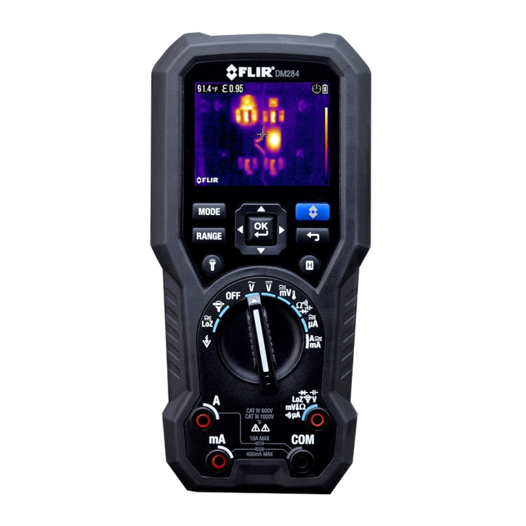
FLIR DM284 User manual

FLIR
FLIR Extech 470 User manual

FLIR
FLIR EXTECH INSTRUMENTS EX520 User manual

FLIR
FLIR IM75-2 User manual

FLIR
FLIR DM286 User manual

FLIR
FLIR DM90 User manual
FLIR
FLIR DM93 User manual