Steinberg Systems SBS-DM-1000NCV User manual

SBS-DM-1000NCV
BEDIENUNGSANLEITUNG
MULTIMETER
USER MANUAL
MULTIMETER
INSTRUKCJA OBSŁUGI
MULTIMETR
NÁVOD K POUŽITÍ
MULTIMETR
MANUEL D´UTILISATION
MULTIMÈTRE
ISTRUZIONI PER L’USO
MULTIMETRO
MANUAL DE INSTRUCCIONES
MULTÍMETRO
DE | EN | PL | CZ | FR | IT | ES

3
09.07.2019
2
Das Produkt erfüllt die geltenden
Sicherheitsnormen.
Gebrauchsanweisung beachten.
Recycling-Produkt.
ACHTUNG! oder WARNUNG! oder HINWEIS!
um auf bestimmte Umstände aufmerksam zu
machen (Allgemeines Warnzeichen).
ACHTUNG! Warnung vor elektrischer Spannung!
Gerät der Schutzklasse II mit Doppelisolierung.
INHALT | CONTENT | TREŚĆ | OBSAH | CONTENU | CONTENUTO | CONTENIDO
Deutsch
English
Polski
Česky
Français
Italiano
Español
3
8
13
18
23
28
33
PRODUKTNAME MULTIMETER
PRODUCT NAME MULTIMETER
NAZWA PRODUKTU MULTIMETR
NÁZEV VÝROBKU MULTIMETR
NOM DU PRODUIT MULTIMÈTRE
NOME DEL PRODOTTO MULTIMETRO
NOMBRE DEL PRODUCTO MULTÍMETRO
MODELL
SBS-DM-1000NCV
PRODUCT MODEL
MODEL PRODUKTU
MODEL VÝROBKU
MODÈLE
MODELLO
MODELO
IMPORTEUR
EXPONDO POLSKA SP. Z O.O. SP. K.
IMPORTER
IMPORTER
DOVOZCE
IMPORTATEUR
IMPORTATORE
IMPORTADOR
ADRESSE VON IMPORTEUR
UL. NOWY KISIELIN-INNOWACYJNA 7, 66-002 ZIELONA GÓRA | POLAND, EU
IMPORTER ADDRESS
ADRES IMPORTERA
ADRESA DOVOZCE
ADRESSE DE L'IMPORTATEUR
INDIRIZZO DELL'IMPORTATORE
DIRECCIÓN DEL IMPORTADOR
Parameter Werte
Produktname Multimeter
Modell SBS-DM-1000NCV
Batterietyp 9V (6F22)/ NEDA 1604
Schutzart IP CAT III 1000V
Schutz vor
Überspannungen
200mV~1000V/ 2V~750V
Messbereich der Spannung
von Gleichstrom/
Wechselstrom
2mA~20A/2mA~20A
Messbereich der
Stromstärke von
Gleichstrom/Wechselstrom
200Ω~20MΩ/
2nF~200uF
Messbereich des
elektrischen Widerstands /
der elektrischen Kapazität
-20~1000°C/200kHz
TECHNISCHE DATEN
Der Begri "Gerät" oder "Produkt" in den Warnungen und
Beschreibung des Handbuchs bezieht sich auf < TRUE
RMS Tischmultimeter - digital AC/DC >. Benutzen Sie das
Gerät nicht in Räumen mit sehr hoher Luftfeuchtigkeit / in
unmittelbarer Nähe von Wasserbehältnissen! Lassen Sie das
Gerät nicht nass werden. Gefahr eines elektrischen Schlags!
Die Ventilationsönungen dürfen nicht verdeckt werden!
2.1. ELEKTRISCHE SICHERHEIT
a) Der Gerätestecker muss mit der Steckdose
kompatibel sein. Ändern Sie den Stecker in keiner
Weise. Original-Stecker und passende Steckdosen
vermindern das Risiko eines elektrischen Schlags.
b) Vermeiden Sie das Berühren von geerdeten
Bauteilen wie Rohrleitungen, Heizkörpern, Öfen und
Kühlschränken. Es besteht das erhöhte Risiko eines
elektrischen Schlags, wenn Ihr Körper durch nasse
Oberächen und in feuchter Umgebung geerdet ist.
Wasser, das in das Gerät eintritt, erhöht das Risiko
von Beschädigungen und elektrischen Schlägen.
c) Berühren Sie das Gerät nicht mit nassen oder
feuchten Händen.
d) Verwenden Sie das Kabel nicht in unsachgemäßer
Weise. Verwenden Sie es niemals zum Tragen
des Geräts oder zum Herausziehen des Steckers.
Halten Sie das Kabel von Hitze, Öl, scharfen
Kanten oder beweglichen Teilen fern. Beschädigte
oder geschweißte Kabel erhöhen das Risiko eines
elektrischen Schlags.
e) Wenn sich die Verwendung des Geräts in feuchter
Umgebung nicht verhindern lässt, verwenden Sie einen
Fehlerstrom-Schutzschalter (RCD). Mit einem RCD
verringert sich das Risiko eines elektrischen Schlags.
2.2. SICHERHEIT AM ARBEITSPLATZ
a) Halten Sie Ihren Arbeitsplatz sauber und gut
beleuchtet. Unordnung oder schlechte Beleuchtung
können zu Unfällen führen. Seien Sie voraussichtig,
beobachten Sie, was getan wird und bewahren
Sie Ihren gesunden Menschenverstand bei der
Verwendung des Gerätes.
b) BenutzenSie dasGerätnichtin explosionsgefährdeten
Bereichen, zum Beispiel in Gegenwart von
brennbaren Flüssigkeiten, Gasen oder Staub. Geräte
können unter Umständen Funken erzeugen, welche
Staub oder Dämpfe entzünden können.
c) Im Falle eines Schadens oder einer Störung sollte
das Gerät sofort ausgeschaltet und dies einer
autorisierten Person gemeldet werden.
d) Wenn Sie nicht sicher sind, ob das Gerät
ordnungsgemäß funktioniert, wenden Sie sich an
den Service des Herstellers.
e) Reparaturen dürfen nur vom Service des Herstellers
durchgeführt werden. Führen Sie keine Reparaturen
auf eigene Faust durch!
f) Zum Löschen des Gerätes bei Brand oder Feuer, nur
Pulver-Feuerlöscher oder Kohlendioxidlöscher (CO2)
verwenden.
g) Kinder und Unbefugte dürfen am Arbeitsplatz nicht
anwesend sein. (Unachtsamkeit kann zum Verlust der
Kontrolle über das Gerät führen).
BEDIENUNGSANLEITUNG
1. ALLGEMEINE BESCHREIBUNG
Diese Anleitung ist als Hilfe für eine sichere und zuverlässige
Nutzung gedacht. Das Produkt wurde strikt nach den
technischen Vorgaben und unter Verwendung modernster
Technologien und Komponenten sowie unter Wahrung der
höchsten Qualitätsstandards entworfen und angefertigt.
VOR INBETRIEBNAHME MUSS DIE ANLEITUNG
GENAU DURCHGELESEN UND VERSTANDEN
WERDEN.
Für einen langen und zuverlässigen Betrieb des Geräts muss
auf die richtige Handhabung und Wartung entsprechend
den in dieser Anleitung angeführten Vorgaben geachtet
werden. Die in dieser Anleitung angegebenen technischen
Daten und die Spezikation sind aktuell. Der Hersteller
behält sich das Recht vor, im Rahmen der Verbesserung
der Qualität.
2. NUTZUNGSSICHERHEIT
ACHTUNG! Lesen Sie alle Sicherheitshinweise und
alle Anweisungen durch. Die Nichtbeachtung der
Warnungen und Anweisungen kann zu elektrischen
Schlägen, Feuer und / oder schweren Verletzungen
bis hin zum Tod führen.
Die originale Anweisung ist die deutschsprachige Fassung.
Sonstige Sprachfassungen sind Übersetzungen aus der
deutschen Sprache.
HINWEIS! In der vorliegenden Anleitung sind
Beispielbilder vorhanden, die von dem tatsächlichen
Aussehen das Produkt abweichen können.
ERLÄUTERUNG DER SYMBOLE
DE

4 5
09.07.2019
der Netzstecker jederzeit zugänglich und nicht verdeckt ist.
Achten Sie darauf, dass die Stromversorgung des Gerätes
den Angaben auf dem Produktschild entspricht.
3.3. GERÄTEBETRIEB
ACHTUNG: Das Symbol und die Beschreibung neben den
Eingangsbuchsen geben die Spannung und die Stromstärke
an, die nicht überschritten werden dürfen, da dies zum Tod
oder zur Beschädigung des Multimeters führen kann.
ACHTUNG: Vergewissern Sie sich vor Beginn der
Messprozedur, dass das Einstellrad: die Auswahl der
Messfunktion und des Messbereichs auf den richtigen
Messbereich eingestellt ist.
ACHTUNG: Wenn Sie sich über die Wertskala des
gemessenen Stroms nicht sicher sind, stellen Sie den
Bereichsschalter auf die höchste Position.
ACHTUNG: Wenn auf dem Bildschirm die Zahl 1 oder -1
angezeigt wird, liegt der gemessene Wert außerhalb der
Skala des ausgewählten Bereichs. Vergrößern Sie den
Messbereich und wiederholen Sie die Messprozedur.
ACHTUNG: Wenn auf dem Display des Geräts
Informationen zur Akkulaufzeit und zum Ersetzen des
Akkus angezeigt werden, sollte man diesen unverzüglich
austauschen.
3.3.1. MESSUNG DER DC GLEICHSPANNUNG
a) Drehen Sie den Drehknopf auf Position V
b) Verbinden Sie die schwarze Messleitung mit der
COMT-Buchse und die rote Messleitung mit der
VΩHz-Buchse.
c) Bringen Sie die Messsonden am zu prüfenden
Stromkreis an
d) Der gemessene Wert wird auf dem LCD-Bildschirm
angezeigt. Die Polarität des roten Kabels wird
zusammen mit dem Gleichspannungswert angezeigt.
3.3.2. MESSUNG DER DC GLEICHSPANNUNG
a) Stellen Sie den Knopf auf Position V~
b) Verbinden Sie die schwarze Messleitung mit der
COMT-Buchse und die rote Messleitung mit der
VΩHz-Buchse
c) Berühren Sie den Testkreis mit beiden Sonden
d) Der gemessene Wert wird auf dem LCD-Bildschirm
angezeigt.
• Bedeutet, dass Sie keine Spannung über
750V anlegen können. Dies kann das Gerät
beschädigen
3.3.3. Messung der DC Stromstärke
a) Stellen Sie den Drehknopf auf Position A
b) Verbinden Sie die schwarze Messleitung mit dem
COMT-Anschluss und die rote mit dem mAT+, um
eine maximale Messung im Bereich von 200 mA
zu erzielen. Schließen Sie das rote Kabel an die
20-A-Buchse an, um den Strom im Bereich von 200
mA bis 20 A zu messen
c) Berühren Sie den Testkreis mit beiden Sonden
d) Der gemessene Wert wird auf dem LCD-Bildschirm
angezeigt. Die Polarität der roten Sonde wird
zusammen mit dem aktuellen Stromwert angezeigt.
• dies bedeutet, dass die maximale Messung
der Steckdose 200 mA nicht überschreitet
• Die Messung im Bereich von 20 A sollte nicht
länger als 10 s dauern, da dies das Risiko einer
Überhitzung der Leitdrähte verringert.
3.3.4. MESSUNG DER AC STROMSTÄRKE
a) Drehen Sie den Drehknopf auf die Position A~
b) Verbinden Sie die schwarze Messsonde mit der COMT-
Buchse und die rote mit dem mAT+, um eine maximale
Messung im Bereich von 200 mA zu erzielen. Schließen
Sie für Messungen im Bereich von 200 mA bis 20 A das
rote Kabel an die 20-A-Buchse an.
c) Berühren Sie den Testkreis mit beiden Sonden
d) Der gemessene Wert wird auf dem LCD-Bildschirm
angezeigt.
• dies bedeutet, dass die maximale Messung
der Steckdose 200 mA nicht überschreitet
• Die Messung an der 20A-Steckdose sollte
nicht länger als 10 Sekunden dauern, um das
Risiko einer Überhitzung des Stromkreises zu
verringern.
3.3.5. WIDERSTANDSMESSUNG
a) Drehen Sie den Drehknopf auf die Position Ω
b) Verbinden Sie die schwarze Sonde mit der COMT-
Buchse und die rote mit der VΩHz-Buchse
c) Berühren Sie den Testkreis mit beiden Sonden
d) Der gemessene Wert wird auf dem LCD-Bildschirm
angezeigt.
• Der maximale abgelesene Messwert beträgt 500
V rms <10 s
• Achtung: Wenn auf dem Bildschirm die Zahl 1
oder -1 angezeigt wird, liegt der gemessene
Wert außerhalb der Skala des ausgewählten
Bereichs. Vergrößern Sie den Messbereich und
wiederholen Sie die Messprozedur.
• Um den Widerstand über 10 MΩ zu messen,
benötigt das Multimeter einen Moment, um den
Messwert zu stabilisieren.
• Wenn der Stromkreis oen ist, zeigt das
Multimeter den Wert "1" oder "-1" an.
• Stellen Sie während der Messung sicher, dass
der Stromkreis von der Stromquelle getrennt ist
und alle Kondensatoren entladen sind.
3.3.6. KAPAZITÄTSMESSUNG
a) Stellen Sie den Knopf auf die Position "F°"
b) Verbinden Sie die schwarze Sonde mit der COMT-
Buchse und die rote mit der mAT + -Buchse
c) Berühren Sie den Testkreis mit beiden Sonden
d) Der gemessene Wert wird auf dem LCD-Bildschirm
angezeigt.
• Die Kondensatoren sollten entladen werden,
bevor die Kapazität gemessen wird.
3.3.7. TEMPERATURMESSUNG
a) Stellen Sie den Drehknopf auf die Position "°C"
b) Schließen Sie den schwarzen Sensor an die COMT-
Buchse und den roten an die mAT+ -Buchse an
c) Berühren Sie den Bereich, dessen Temperatur
gemessen werden soll
d) Der gemessene Wert wird auf dem LCD-Bildschirm
angezeigt.
• Die Messgrenze für Thermoelemente liegt bei
250 °C. Zur Messung höherer Temperaturen
sollte eine an den höheren Temperaturbereich
angepasste Sonde verwendet werden.
• Bleiben Sie beim Messen der Temperatur
konsequent
3.3.8. FREQUENZMESSUNG
a) Stellen Sie den Drehknopf auf die Position 200kHz
b) Verbinden Sie die schwarze Sonde mit der COMT-
Buchse und die rote Sonde mit der VΩHz-Buchse
DE
ACHTUNG! Obwohl das Gerät mit dem Gedanken an
die Sicherheit entworfen wurde, besitzt es bestimmte
Schutzmechanismen. Trotz der Verwendung
zusätzlicher Sicherheitselemente besteht bei der
Bedienung immer noch ein Verletzungsrisiko. Es wird
empfohlen, bei der Nutzung Vorsicht und Vernunft
walten zu lassen.
3. NUTZUNGSBEDINGUNGEN
Das Gerät dient zur Messung von elektrischen Werten
sowie der Temperatur von ausgewählten Geräten und
Stromkreisen. Für alle Schäden bei nicht sachgemäßer
Verwendung haftet allein der Betreiber.
3.1. GERÄTEBESCHREIBUNG
3.2. VORBEREITUNG ZUR VERWENDUNG
ARBEITSPLATZ DES GERÄTES
VORBEREITUNG ZUM BETRIEB
Die Umgebungstemperatur sollte zwischen 18 °C und 28
°C betragen (64°F bis 82°F) und die relative Luftfeuchtigkeit
sollte 70 % nicht überschreiten. Stellen Sie das Gerät so
auf, dass eine gute Luftzirkulation gewährleistet ist. Es ist
auf allen Seiten ein Mindestabstand von wenigstens 10 cm
einzuhalten. Halten Sie das Gerät von allen heißen Flächen
fern. Betreiben Sie das Gerät stets auf einer ebenen,
stabilen, sauberen, feuerfesten und trockenen Fläche und
außerhalb der Reichweite von Kindern oder Personen mit
geistigen Behinderungen. Platzieren Sie das Gerät so, dass
ACHTUNG: Die Explosionszeichnungen von diesem
Produkt benden sich auf den letzten Seiten der
Bedienungsanleitung S. 38.
1. Spannungsdetektor (NCV)
2. CDS Sensor
3. Rote Diode: Spannungsdetektion
4. Grüne Diode: Spannungsdetektion
5. LCD Display.
6. Mit der POWER-Taste wird das Gerät ein- oder
ausgeschaltet.
7. D.HOLD Taste: zur Aufrechterhaltung des Ergebnisses
8. NCV-Taste, Einschalten (grünes Licht) / Ausschalten
des berührungslosen Messmodus
9. Drehknopf: Wahl der Funktionen und des
Messbereichs
10. Eingangsbuchse: mA T+, dient zum Lesen des
Kondensators, mA und Temperatur "+".
11. Eingangsbuchse: 20A.
12. Eingangsbuchse: Ω VΩHz: V / 200kHz.
13. Eingangsbuchse: T COMT-: COM und Temperatur „-”.
14. Eingangsbuchse: hFE
j) Das Gerät ist kein Spielzeug. Reinigung und Wartung
dürfen nicht von Kindern ausgeführt werden, wenn
diese nicht unter der Aufsicht von Erwachsenen
stehen.
k) Messen Sie niemals die Spannung, wenn die
Messleitungen an die Strommessbuchsen
angeschlossen sind.
l) Seien Sie vorsichtig, wenn Sie mit Spannungen über
DC 60 V oder AC 4 2V arbeiten.
m) Lassen Sie die Messleitungen oder Sonden während
der Messung hinter isolierten Teilen.
n) Wählen Sie die geeignete Funktion und den
geeigneten Messbereich für die Messung, um eine
Beschädigung des Messgeräts zu vermeiden.
o) Trennen Sie die Messleitungen von den Testpunkten,
bevor Sie zu einer anderen Funktion wechseln.
DE
h) Überprüfen Sie regelmäßig den Zustand der
Sicherheitsinformationsaufkleber. Falls die Aufkleber
unleserlich sind, sollten sie ausgetauscht werden.
i) Bewahren Sie die Gebrauchsanleitung für den
weiteren Gebrauch auf. Sollte dieses Gerät
an Dritte weitergegeben werden, muss die
Gebrauchsanleitung mit ausgehändigt werden.
HINWEIS! Kinder und Unbeteiligte müssen bei der
Arbeit mit diesem Gerät gesichert werden.
2.3. PERSÖNLICHE SICHERHEIT
a) Es ist nicht gestattet, das Gerät im Zustand der
Ermüdung, Krankheit, unter Einuss von Alkohol,
Drogen oder Medikamenten zu betreiben,
wenn diese die Fähigkeit das Gerät zu bedienen,
einschränken.
b) Das Gerät ist nicht dazu bestimmt, durch Personen
(darunter Kinder) mit eingeschränkten physischen,
sensorischen und geistigen Fähigkeiten bzw. durch
Personen ohne entsprechende Erfahrung und/oder
entsprechendes Wissen bedient zu werden, es sei
denn es gibt eine für ihre Aufsicht und Sicherheit
zuständige Person bzw. sie haben von dieser Person
entsprechende Hinweise in Bezug auf die Bedienung
das Gerät erhalten.
c) Seien Sie aufmerksam und verwenden Sie Ihren
gesunden Menschenverstand beim Betreiben
des Gerätes. Ein Moment der Unaufmerksamkeit
während der Arbeit kann zu schweren Verletzungen
führen.
d) Um eine versehentliche Inbetriebnahme zu
vermeiden, vergewissern Sie sich, dass der
Schalter vor dem Anschließen an eine Stromquelle
ausgeschaltet ist.
e) Das Gerät ist kein Spielzeug. Kinder sollten unter
Aufsicht stehen, damit sie nicht mit dem Gerät
spielen.
2.4. SICHERE ANWENDUNG DES GERÄTS
a) Benutzen Sie das Gerät nicht, wenn der EIN-/AUS-
Schalter nicht ordnungsgemäß funktioniert. Geräte,
die per Schalter nicht gesteuert werden können sind
gefährlich und müssen repariert werden.
b) Nicht verwendete Werkzeuge sind außerhalb
der Reichweite von Kindern sowie von Personen
aufzubewahren, welche weder das Gerät selbst, noch
die entsprechende Anleitung kennen. In den Händen
unerfahrener Personen können derlei Geräte eine
Gefahr darstellen.
c) Halten Sie das Gerät im einwandfreien Zustand.
d) Halten Sie das Gerät außerhalb der Reichweite von
Kindern.
e) Reparatur und Wartung von Geräten dürfen nur
von qualiziertem Fachpersonal und mit Original-
Ersatzteilen durchgeführt werden. Dadurch wird die
Sicherheit bei der Nutzung gewährleistet.
f) Um die vorgesehene Betriebsintegrität des Gerätes
zu gewährleisten, dürfen die werksmäßig montierten
Abdeckungen oder Schrauben nicht entfernt werden.
g) Es ist verboten, das Gerät während der Arbeit zu
schieben, umzustellen oder umzudrehen.
h) Lassen Sie dieses Gerät nicht unbeaufsichtigt,
während es in Betrieb ist.
i) Das Gerät regelmäßig reinigen, damit sich kein
Schmutz auf Dauer festsetzen kann.

6 7
09.07.2019
Dioden- und Schallprüfung
Überlastungsschutz: 500V DC or AC rms
Testen des hFE-Transistors
Prüfungsumfang: 0-1000
Ib=10µA, Vce=3.0V ca.
6-11 Berührungslose Erkennung der AC Wechselspannung
Test zur Bestimmung des Spannungsbereichs: 90V~1000V
AC rms
3.5 REINIGUNG UND WARTUNG
a) Verwenden Sie zur Reinigung der Oberäche
ausschließlich Mittel ohne ätzende Inhaltsstoe.
b) Lassen Sie nach jeder Reinigung alle Teile gut
trocknen, bevor das Gerät erneut verwendet wird.
c) Bewahren Sie das Gerät an einem trockenen, kühlen,
vor Feuchtigkeit und direkter Sonneneinstrahlung
geschütztem Ort auf.
d) Es ist verboten, das Gerät mit einem Wasserstrahl zu
besprühen oder in Wasser zu tauchen.
e) In Hinblick auf technische Ezienz und zur
Vorbeugung vor Schäden sollte das Gerät regelmäßig
überprüft werden.
f) Benutzen Sie einen weichen Lappen zur Reinigung.
g) Entfernen Sie die Batterie aus dem Gerät, wenn es
über einen längeren Zeitraum nicht genutzt wird.
h) Schützen Sie das Gerät vor Feuchtigkeit. Wenn es
nass wird, wischen Sie es sofort trocken. Flüssigkeiten
können Mineralien enthalten, die elektronische
Schaltungen angreifen können.
i) Verwenden und lagern Sie das Gerät unter normalen
Temperaturbedingungen. Extreme Temperaturen
können die Lebensdauer des Geräts verkürzen, die
Batterien beschädigen und Kunststoteile verformen
oder schmelzen.
Reich-
weite Beschreibung Testumgebungen
Ausgeblendeter
Ablesewert ungefähr,
aufgerundet
Gleichstrom DC ca.
1mA
Wechselstrom DC
ca. 3V
Der Ton ertönt, wenn
der Widerstand 50 Ω
nicht überschreitet
Spannung im
oenen Schaltkreis
ca. 3 V
3. Ersetzen Sie die Sicherung durch eine neue mit den
gleichen Parametern.
4. Montieren Sie erneut den Sicherungssockel.
ACHTUNG! Wenden Sie beim Entfernen und
Installieren des Sicherungssockels keine
übermäßige Kraft an, um eine Beschädigung der
Sicherungssockels zu vermeiden
DE
3.4. SPEZIFIKATIONEN
Spannung DC
Intensität AC
Widerstand
Kapazität
Intensität DC
Rdg - Ablesung. Dgt - Zier
Eingangsimpedanz: 10MΩ
Überlastungsschutz: 1000V DC or 750V AC rms
Überlastungsschutz: 200mA/500V & 20A/500V Schnelle
Sicherung Wichtig: 20A bis 10 Sekunden
Überlastungsschutz: 200mA/500V & 20A/500V Schnelle
Sicherung. Wichtig: 20A bis 10 Sekunden
Frequenzbereich: 40 to 400Hz
Überlastungsschutz: 500V DC or AC rms
Reichweite Verlässlichkeit Genauigkeit
200mV 0,1mV
±(0,5% of rdg*
+ 2dgt*)
2V 1mV
20V 10mV
200V 100mV
1000V 1V ±(0,8% of rdg
+ 2dgt)
Reichweite Verlässlichkeit Genauigkeit
2mA 1μA ±(1,5% of rdg
+ 3dgt)
200mA 100μA
20A 10mA ±(2,5% of rdg
+ 5dgt)
Reichweite Verlässlichkeit Genauigkeit
200Ω 0.1Ω ±(1,0% of rdg
+ 3 dgt)
2kΩ 1Ω
±(1,0% of rdg
+ 2 dgt)
20kΩ 10Ω
200kΩ 100Ω
20MΩ 10kΩ ±(1,5% of rdg
+ 3 dgt)
Reichweite Verlässlichkeit Genauigkeit
2nF
±(2.5% of rdg +
5 dgt)
1pF
20nF 10pF
100pF
200nF
1nF
2µF
200µF ±(5.0% of rdg +
10 dgt) 100nF
Reichweite Verlässlichkeit Genauigkeit
2mA 1μA
±(1,2% of rdg
+ 2dgt)
20mA 10μA
200mA 100μA
20A 10mA ±(2,0% of rdg
+ 3dgt)
c) Berühren Sie den Testkreis mit beiden Sonden
d) Der gemessene Wert wird auf dem LCD-Bildschirm
angezeigt.
3.3.9. DIODEN-UND SCHALLPRÜFUNG
a) Drehen Sie den Drehknopf auf die Position
b) Verbinden Sie die schwarze Sonde mit der COMT-
Buchse und die rote mit der VΩHz-Buchse
c) Schließen Sie die Messsonden an die gemessene
Diode an. Das Display zeigt den Wert der
Datenspannung aufgerundet an.
d) Schließen Sie beim Testen des Audiosignals die
Prüfspitzen an die beiden Schaltungspunkte an.
Wenn der Widerstand des Stromkreises weniger als
50 Ω beträgt, wird das Gerät ein Signal geben.
• Stellen Sie während des Tests sicher, dass der
Stromkreis von der Stromquelle getrennt ist und
alle Kondensatoren entladen sind
3.3.10. TESTEN DES HFE-TRANSISTORS
a) Stellen Sie den Drehknopf auf die Position "hFE"
b) Stellen Sie fest, ob es sich um einen NPN- oder PNP-
Transistor handelt, und lokalisieren Sie die Emitter-,
Basis- und Kollektordrähte. Legen Sie die Drähte in
die entsprechenden Löcher des Frontpaneels
c) Der gemessene Wert wird auf dem LCD-Bildschirm
angezeigt.
• Keine externe Spannung an das Messterminal
anschließen
3.3.11. BERÜHRUNGSLOSE ERKENNUNG DER AC
WECHSELSPANNUNG
a) Halten Sie die Taste "NCV" gedrückt. Das Messgerät
wechselt in den berührungslosen Messmodus. Die
grüne LED-Diode leuchtet auf.
b) Zentrieren Sie das Gerät und zielen Sie dann auf den
getesteten Stromkreis.
c) Wenn die Stromkreisspannung 90 V AC rms nicht
überschreitet oder gleich ist, leuchten ein rotes und
ein grünes Licht auf und ein akustisches Signal ertönt.
d) Um den NCV-Modus zu verlassen,
lassen Sie die Taste "NCV" los
ACHTUNG: Seien Sie vorsichtig, wenn Sie das
Vorhandensein elektrischer Spannung mithilfe der
berührungslosen Messfunktion bestimmen, um einen
Stromschlag zu vermeiden. Wenn das Multimeter
die Spannung nicht erkennt, ist die Spannung
möglicherweise noch vorhanden. Verlassen Sie sich
nicht auf die NCV-Funktion, wenn Sie feststellen, ob
unter Spannung stehende Leitdrähte vorhanden sind.
• Vermeiden Sie elektrische Störungen, wenn Sie
ein Multimeter im NCV-Modus verwenden
Empndlichkeit: sinusförmig 1V rms
Sicherung: 500V DC or AC rms
Frequenz
Reichweite Verlässlichkeit Genauigkeit
200kHz ± (2,0% of rdg + 5 dgt) 100Hz
DE
j) Mit dem Gerät vorsichtig und feinfühlig umgehen.
Ein Herunterfallen des Gerätes kann die Leiterplatten
beschädigen und zu Fehlfunktionen des Gerätes
führen.
k) Das Gerät vor Staub und Schmutz schützen.
l) verwenden Sie nur neue Batterien der in den
technischen Daten angegebenen Größe und des
angegebenen Typs. Bevor die Batterien eingelegt
oder ausgetauscht werden, muss sichergestellt
werden, dass das Gerät an keinen externen
Stromkreis angeschlossen und dass der Regulator
auf „OFF“ gestellt ist und dass die Messleitungen von
den Klemmen getrennt sind.
SICHERE ENTSORGUNG VON AKKUMULATOREN UND
BATTERIEN
Verwenden Sie für das Gerät AA Batterien mit 1,5 V.
Entnehmen Sie verbrauchte Batterien aus dem Gerät.
Führen Sie dazu die gleichen Schritte durch wie beim
Einsetzen der Batterien. Entsorgen Sie leere Batterien bei
den entsprechenden Abgabestellen.
ENTSORGUNG GEBRAUCHTER GERÄTE
Dieses Produkt darf nicht über den normalen Hausmüll
entsorgt werden. Geben Sie das Gerät bei entsprechenden
Sammel- und Recyclinghöfen für Elektro- und
Elektronikgeräte ab. Überprüfen Sie das Symbol auf dem
Produkt, der Bedienungsanleitung und der Verpackung. Die
bei der Konstruktion des Gerätes verwendeten Kunststoe
können entsprechend ihrer Kennzeichnung recycelt werden.
Mit der Entscheidung für das Recycling leisten Sie einen
wesentlichen Beitrag zum Schutz unserer Umwelt. Wenden
Sie sich an die örtlichen Behörden, um Informationen
über Ihre lokale Recyclinganlagen zu erhalten. Austausch
der Sicherung ACHTUNG! Die Sicherung sollte von einem
spezialsierten Fachmann ausgetauscht werden!
1. Trennen Sie das Gerät von der Stromversorgung.
2. Trennen Sie das Netzkabel und entfernen Sie den
Sicherungssockel.
Spannung AC
Eingangsimpedanz: 10MΩ
Überlastungsschutz: 1000V DC or 750 AC rms
Frequenzbereich: 40 to 400Hz
Reichweite Verlässlichkeit Genauigkeit
2V 1mV
±(1,0% of rdg
+ 2dgt)
20V 10mV
200V 100mV
750V 1V ±(1,2% of rdg
+ 3dgt) NiCr-NiSi K-Sensorentyp
Überlastungsschutz: 200mA/500V Sicherung
Temperatur
Überlastungsschutz: 200mA/500V Sicherung
Reichweite Verlässlichkeit Genauigkeit
°C
-20~150°C ± (3°C
+ 1digit) 1°C
150~1000°C ± (3% of rdg
+ 2dgt)

8 9
09.07.2019
ATTENTION! Despite the safe design of the device
and its protective features, and despite the use of
additional elements protecting the operator, there is
still a slight risk of accident or injury when using the
device. Stay alert and use common sense when using
the device.
3. USE GUIDELINE
Multimeter is used to measure the electrical values of
selected devices and electrical circuits.
The user is liable for any damage resulting from
unintended use of the device.
3.1. DEVICE DESCRIPTION
3.2. PREPARING FOR USE
The ambient temperature should be between 18°C and
28°C (64°F to 82°F), and the relative humidity should not
exceed 70. Ensure good ventilation in the room in which
the device is being used. There should be at least 10 cm
distance between each side of the device and the wall or
other objects. Keep the device away from hot surfaces.
Operate the device on an even, stable, clean, re-proof and
dry surface and out of the reach of children and persons
with mental disabilities. Position the device such that you
always have access to the power plug. The power cord
connected to the appliance must be properly grounded
and correspond to the technical details on the product
label!
3.3. WORKING WITH THE DEVICE
PLEASE NOTE: The symbol and the description next
to the input sockets stands for voltage and current levels
which can not be exceeded as it may cause loss of life or
damage to health and impair the multimeter.
PLEASE NOTE: Before starting the measurement make sure
that the function selection and measurement range dial is
set to the correct range
PLEASE NOTE: If you are not sure about the scale of the
measured current, set the range switch to the top position
PLEASE NOTE: If numbers 1 or -1 are shown on the display,
the measured value is out of the selected range scale.
Increase the measuring range and try again.
PLEASE NOTE: If the device displays the low battery
message, the battery needs to be replaced.
3.3.1. DC VOLTAGE MEASUREMENT
a) Turn the dial to V ”
b) Connect the black test lead to the COMT terminal
and the red test lead to the VΩHz terminal.
c) Hook the measuring probes to the tested circuit
d) The measured value will be displayed on the LCD
screen. The polarity of the red lead will be indicated,
and the DC voltage value.
3.3.2. AC VOLTAGE MEASUREMENT
a) Turn the dial to V~.
b) Connect the black test lead to the COMT terminal
and the red test lead to the VΩHz terminal.
c) Touch the tested circuit with both probes
d) The measured value will be displayed on the LCD
screen.
ATTENTION! This product’s exploded view can be
found on the last pages of the operating instructions
(pp. 38).
1. Voltage detector (NCV)
2. CDS sensor
3. Red LED: voltage detection
4. Green LED: voltage detection
5. LCD display
6. POWER button, turns the device on / off.
7. D.HOLD button/Backlight: Lock/unlock the displayed
value
8. NCV button enables (green lamp) or disables
contactless measurement mode
9. Knob: selecting the function and measuring range.
10. Input socket: mA T +, used for reading the capacitor
, mA and temperature "+" .
11. Input socket: 20A.
12. Input socket: Ω VΩHz: V / 200kHz.
13. Input socket: T COMT-: COM and temperature "-".
14. Input socket: hFE
EN
Parameter description Parameter value
Product name Multimeter
Model SBS-DM-1000NCV
Battery type 9V (6F22)/ NEDA 1604
Protection rating IP CAT III 1000V
Over Voltage Protection 200mV~1000V/ 2V~750V
Measuring range of direct/
alternating current voltage
2mA~20A/2mA~20A
Measuring range of
direct/alternating current
amperage
200Ω~20MΩ/
2nF~200uF
Measuring range of
electrical resistance/
capacitance
-20~1000°C/200kHz
TECHNICAL DATE The terms "device" or "product" are used in the warnings
and instructions to refer to < Multimeter >. Do not use in
very humid environments or in the direct vicinity of water
tanks. Prevent the device from getting wet. Risk of electric
shock! Do not cover the ventilation openings!
2.1. ELECTRICAL SAFETY
a) The plug must t the socket. Do not modify the
plug in any way. Using original plugs and matching
sockets reduces the risk of electric shock.
b) Avoid touching earthed elements such as pipes,
heaters, boilers and refrigerators. There is an
increased risk of electric shock if the earthed device
is exposed to rain, comes into direct contact with a
wet surface or is operating in a damp environment.
Water getting into the device increases the risk of
damage to the device and of electric shock.
c) Do not touch the device with wet or damp hands.
d) Use the cable only for its designated use. Never use it
to carry the device or to pull the plug out of a socket.
Keep the cable away from heat sources, oil, sharp
edges or moving parts. Damaged or tangled cables
increase the risk of electric shock.
e) If using the device in a damp environment cannot
be avoided, a residual current device (RCD) should
be applied. The use of an RCD reduces the risk of
electric shock.
2.2. SAFETY IN THE WORKPLACE
a) Make sure the workplace is clean and well lit. A
messy or poorly lit workplace may lead to accidents.
Try to think ahead, observe what is going on and use
common sense when working with the device.
b) Do not use the device in a potentially explosive
environment, for example in the presence of
ammable liquids, gases or dust. The device
generates sparks which may ignite dust or fumes.
c) If you discover damage or irregular operation,
immediately switch the device o and report it to a
supervisor without delay.
d) If there are any doubts as to the correct operation
of the device, contact the manufacturer's support
service.
e) Only the manufacturer's service point may repair the
device. Do not attempt any repairs independently!
f) In case of re, use a powder or carbon dioxide
(CO2) re extinguisher (one intended for use on live
electrical devices) to put it out.
g) Children or unauthorised persons are forbidden to
enter a work station. (A distraction may result in loss
of control over the device)
h) Regularly inspect the condition of the safety labels. If
the labels are illegible, they must be replaced.
i) Please keep this manual available for future
reference. If this device is passed on to a third party,
the manual must be passed on with it.
USER MANUAL
1. GENERAL DESCRIPTION
The user manual is designed to assist in the safe and
trouble-free use of the device. The product is designed
and manufactured in accordance with strict technical
guidelines, using state-of-the-art technologies and
components. Additionally, it is produced in compliance
with the most stringent quality standards.
DO NOT USE THE DEVICE UNLESS YOU HAVE
THOROUGHLY READ AND UNDERSTOOD THIS
USER MANUAL.
To increase the product life of the device and to ensure
trouble-free operation, use it in accordance with this user
manual and regularly perform maintenance tasks. The
technical data and specications in this user manual are
up to date. The manufacturer reserves the right to make
changes associated with quality improvement.
2. USAGE SAFETY
ATTENTION! Read all safety warnings and all
instructions. Failure to follow the warnings and
instructions may result in electric shock, re and/or
serious injury or even death.
The original operation manual is written in German. Other
language versions are translations from the German.
PLEASE NOTE! Drawings in this manual are for
illustration purposes only and in some details may
dier from the actual product.
LEGEND
The product satises the relevant safety
standards.
Read instructions before use.
The product must be recycled.
WARNING! or CAUTION! or REMEMBER!
Applicable to the given situation. (general
warning sign)
ATTENTION! Electric shock warning!
Class II protection device with double
insulation.
REMEMBER! When using the device, protect
children and other bystanders.
EN
2.3. PERSONAL SAFETY
a) Do not use the device when tired, ill or under the
inuence of alcohol, narcotics or medication which
can signicantly impair the ability to operate the
device.
b) The device is not designed to be handled by persons
(including children) with limited mental and sensory
functions or persons lacking relevant experience
and/or knowledge unless they are supervised by
a person responsible for their safety or they have
received instruction on how to operate the device.
c) When working with the device, use common sense
and stay alert. Temporary loss of concentration while
using the device may lead to serious injuries.
d) To prevent the device from accidentally switching on,
make sure the switch is on the OFF position before
connecting to a power source.
e) The device is not a toy. Children must be supervised
to ensure that they do not play with the device.
2.4. SAFE DEVICE USE
a) Do not use the device if the ON/OFF switch does not
function properly (does not switch the device on and
o). Devices which cannot be switched on and o
using the ON/OFF switch are hazardous, should not
be operated and must be repaired.
b) When not in use, store in a safe place, away from
children and people not familiar with the device who
have not read the user manual. The device may pose
a hazard in the hands of inexperienced users.
c) Keep the device in perfect technical condition.
d) Keep the device out of the reach of children.
e) Device repair or maintenance should be carried out
by qualied persons, only using original spare parts.
This will ensure safe use.
f) To ensure the operational integrity of the device, do
not remove factory-tted guards and do not loosen
any screws.
g) Do not move, adjust or rotate the device in the
course of work.
h) Do not leave this appliance unattended while it is in
use.
i) Clean the device regularly to prevent stubborn grime
from accumulating.
j) The device is not a toy. Cleaning and maintenance
may not be carried out by children without
supervision by an adult person.
k) Never measure the voltage when the test leads are
connected to the amperage measurement sockets.
l) Exercise caution when working with voltages above
DC60V or AC42V.
m) During measurement, hold the test leads or probes
by the insulated parts.
n) Select the appropriate function and measurement
to avoid damage to the multimeter during the
measurement.
o) Disconnect the test leads from the test points before
switching to another function.

10 11
09.07.2019
Voltage DC
Voltage AC
Amperage AC
Resistance
Capacity
Amperage DC
Rdg – reading.. Dgt - digit
Input impedance: 10MΩ
Overload protection: 1000V DC or 750V AC rms
Overload protection: 200mA/500V & 20A/500V Quick fuse
Please note: 20A to 10 seconds
Input impedance: 10MΩ (2V range is 1MΩ)
Overload protection: 1000V DC or 750 AC rms
frequency range: 40 to 400Hz
NiCr-NiSi K-type of sensor
Overload protection: 200mA/500V fuse
Overload protection: 200mA/500V & 20A/500V fuse
Please note: 20A to 10 seconds
frequency range: 40 to 400Hz
Overload protection: 500V DC or AC rms
Temperature
Range Surety Precision
200mV 0,1mV
±(0,5% of rdg*
+ 2dgt*)
2V 1mV
20V 10mV
200V 100mV
Range Surety Precision
2V 1mV
±(1,0% of rdg
+ 2dgt)
20V 10mV
200V 100mV
750V 1V ±(1,2% of rdg
+ 3dgt)
Range Surety Precision
2mA 1μA ±(1,5% of rdg
+ 3dgt)
200mA 100μA
20A 10mA ±(2,5% of rdg
+ 5dgt)
Range Surety Precision
200Ω 0.1Ω ±(1,0% of rdg
+ 3 dgt)
2kΩ 1Ω
±(1,0% of rdg
+ 2 dgt)
20kΩ 10Ω
200kΩ 100Ω
20MΩ 10kΩ ±(1,5% of rdg
+ 3 dgt)
Range Surety Precision
2nF
±(2.5% of rdg +
5 dgt)
1pF
20nF 10pF
100pF
200nF
1nF
2µF
200µF ±(5.0% of rdg +
10 dgt) 100nF
Range Surety Precision
°C
-20~150°C ± (3°C
+ 1digit) 1°C
150~1000°C ± (3% of rdg
+ 2dgt)
Range Surety Precision
2mA 1μA
±(1,2% of rdg
+ 2dgt)
20mA 10μA
200mA 100μA
20A 10mA ±(2,0% of rdg
+ 3dgt) Sensitivity: sinusoid1V rms
fuse: 500V DC or AC rms
Frequency
Range Surety Precision
200kHz ± (2,0% of rdg + 5 dgt) 100Hz
EN
• Means that you must not use voltage
exceeding 750V, It may damage the device
3.3.3. DC MEASUREMENT
a) Turn the dial to A
b) Connect the black test lead to the COMT terminal
and the red one to the mAT+ terminal for maximum
measurement in the 200mA range. To measure
current in the range between 200mA and 20A,
connect the red lead to the 20A terminal
c) Touch the tested circuit with both probes.
d) The measured value will be displayed on the LCD
screen. The polarity of the red probe and the current
value will be displayed.
• Means that the maximum measurement of
the terminal will not exceed 200mA
• Measurement in the 20A range should not be
longer than 10 for fear of increasing the risk of
overheating the leads.
3.3.4. AC MEASUREMENT
a) Turn the dial to “A~”
b) Connect the black test lead to the COMT terminal
and the red one to the mAT+ terminal for maximum
measurement in the 200mA range. To measure
current in the range between 200mA and 20A,
connect the red lead to the 20A terminal.
c) Touch the tested circuit with both probes
d) The measured value will be displayed on the LCD screen.
• Means that the maximum measurement of
the terminal will not exceed 200mA
• Measurement using the 20A terminal should
not be longer than 10 for fear of increasing the
risk of overheating the leads.
3.3.5. RESISTANCE MEASUREMENT
a) Turn the dial to Ω
b) Connect the black test lead to the COMT terminal
and the red test lead to the VΩHz terminal.
c) Touch the tested circuit with both probes
d) The measured value will be displayed on the LCD
screen
• The maximum reading is 500V rms <10sec
• Please Note: If numbers 1 or -1 are shown on
the display, the measured value is out of the
selected range scale. Increase the measuring
range and try again.
• To measure the resistance above 10M Ω, the
multimeter will need a moment to stabilize the
reading.
• If the circuit is open, the multimeter displays "1"
or "-1".
• During the measurement, make sure that the
circuit is disconnected from the power source
and that all capacitors are discharged.
3.3.6. CAPACITANCE MEASUREMENT
a) Turn the dial to „F°”
b) Connect the black test lead to the COMT terminal
and the red test lead to the VΩHz terminal.+
c) Touch the tested circuit with both probes
d) The measured value will be shown on the display.
• The capacitors should be discharged before
capacitance is measured
3.3.7. TEMPERATURE MEASUREMENT
a) Turn the dial to “°C”
b) Connect the black senor to the COMT terminal and
the red sensor to the mAT+ terminal.
c) Touch the area where the temperature will be
measured
d) The measured value will be displayed on the LCD
screen
• The thermocouple measurement limit is 250°C. To
measure higher temperatures, a probe adapted to
the higher temperature ranges should be used.
• Be consistent when measuring the temperature.
3.3.8. FREQUENCY MEASUREMENT
a) Turn the dial to 200kHz
b) Connect the black test lead to the COMT terminal
and the red test lead to the VΩHz terminal.
c) Touch the tested circuit with both probes
d) The measured value will be shown on the display.
3.3.9. TESTING THE DIODE AND THE BEEP
a) Turn the dial to
b) Connect the black test lead to the COMT terminal
and the red test lead to the VΩHz terminal.
c) Hook the measuring probes to the measured
diode, the display will show the value of the voltage
rounded up.
d) When testing the audio signal, connect the test
probes to two points in the circuit. If the resistance
of the circuit is less than 50 Ω, the device will beep.
• During the test, make sure that the circuit is
disconnected from the power source and that
all capacitors are discharged
3.3.10. TESTING THE HFE TRANSISTOR
a) Turn the dial to „hFE”
b) Determine whether it is an NPN or PNP transistor
and locate the emitter, base and collector leads.
Place the leads in the corresponding terminals on
the front panel
c) The measured value will be shown on the display.
• do not connect external voltage to the
measuring terminal
3.3.11. NON-CONTACT AC DETECTION
a) Press and hold the "NCV" button, the meter will
enter the non-contact measurement mode. The
green LED will light up.
b) Centre the device and then aim it at the tested circuit.
c) If the circuit voltage does not exceed or equals 90 V
AC rms, a red and green light will come on and the
device will beep.
d) To exit the NCV mode, release the "NCV" button
PLEASE NOTE: Use caution when determining the
presence of electrical voltage using the non-contact
measurement function to avoid electric shock. If the
multimeter does not detect the voltage, voltage may
still be present. Do not rely on the NCV function
while determining the presence of live wires.
• When using a multimeter in NCV mode, avoid
any kind of electrical interference
3.4. SPECIFICATIONS
EN
Overload protection: 200mA/500V fuse
Testing the diode and the beep
Overload protection: 500V DC or AC rms
Testing the hFE transistor
The test range: 0-1000
Ib=10µA, Vce=3.0V approx.
6-11 Non-contact AC detection
Voltage range test: 90V~1000V AC rms
Range Description Test conditions
Readout displayed
in approximation,
rounded up
DC approx. 1mA
AC approx. 3V
The device will beep
if the resistance does
not exceed 50 Ω
Open circuit voltage
approx. 3V
3.5 CLEANING AND MAINTENANCE
a) Use only non-corrosive cleaners to clean the surface.
b) After cleaning the device, all parts should be dried
completely before using it again.
c) Store the unit in a dry, cool place, free from moisture
and direct exposure to sunlight.
d) Do not spray the device with a water jet or submerge
it in water.
e) The device must be regularly inspected to check its
technical eciency and spot any damage.
f) Use a soft cloth for cleaning.
g) Do not leave the battery in the device if it will not be
used for a longer period of time.
h) Protect the device against moisture. If it is wet, wipe
it dry immediately. Liquids may contain minerals
which can corrode electronic circuits.
Range Surety Precision
1000V 1V ±(0,8% of rdg
+ 2dgt)

12 13
09.07.2019
EN
Opis parametru Wartość parametru
Nazwa produktu Multimetr
Model SBS-DM-1000NCV
Typ baterii 9V (6F22)/ NEDA 1604
Ochrona
przeciwprzepięciowa
CAT III 1000V
Zakres pomiaru
napięcia prądu stałego/
przemiennego
200mV~1000V/ 2V~750V
Zakres pomiaru
natężenia prądu stałego/
przemiennego
2mA~20A/2mA~20A
Zakres pomiaru oporu/
pojemności elektrycznej
200Ω~20MΩ/
2nF~200uF
Zakres pomiaru
temperatury/ częstotliwości
-20~1000°C/200kHz
DANE TECHNICZNE
Termin „urządzenie” lub „produkt” w ostrzeżeniach i w opisie
instrukcji odnosi się do <MULTIMETR CYFROWY TRUE RMS
AC/DC>. Nie należy używać urządzenia w pomieszczeniach
o bardzo dużej wilgotności/w bezpośrednim pobliżu
zbiorników z wodą! Nie wolno dopuszczać do zamoczenia
urządzenia. Ryzyko porażenia prądem!
2.1. BEZPIECZEŃSTWO ELEKTRYCZNE
a) Wtyczka urządzenia musi pasować do gniazda.
Nie modykować wtyczki w jakikolwiek sposób.
Oryginalne wtyczki i pasujące gniazda zmniejszają
ryzyko porażenia prądem.
b) Unikać dotykania uziemionych elementów, takich jak
rury, grzejniki, piece i lodówki. Istnieje zwiększone
ryzyko porażenia prądem, jeśli ciało jest uziemione
i dotyka urządzenia narażonego na bezpośrednie
działanie deszczu, mokrej nawierzchni i pracy
w wilgotnym otoczeniu. Przedostanie się wody do
urządzenia zwiększa ryzyko jego uszkodzenia oraz
porażenia prądem.
c) Nie wolno dotykać urządzenia mokrymi lub
wilgotnymi rękoma.
d) Nie należy używać przewodu w sposób niewłaściwy.
Nigdy nie używać go do przenoszenia urządzenia lub
do wyciągania wtyczki z gniazda. Trzymać przewód
z dala od źródeł ciepła, oleju, ostrych krawędzi
lub ruchomych części. Uszkodzone lub poplątane
przewody zwiększają ryzyko porażenia prądem.
e) Jeśli nie można uniknąć używania urządzenia
w środowisku wilgotnym, należy stosować wyłącznik
różnicowo-prądowy (RCD). Używanie RCD zmniejsza
ryzyko porażenia prądem.
2.2. BEZPIECZEŃSTWO W MIEJSCU PRACY
a) Utrzymywać porządek w miejscu pracy i dobre
oświetlenie. Nieporządek lub złe oświetlenie może
prowadzić do wypadków. Należy być przewidującym,
obserwować co się robi i zachowywać rozsądek
podczas używania urządzenia.
b) Nie używać urządzenia w stree zagrożenia
wybuchem, na przykład w obecności łatwopalnych
cieczy, gazów lub pyłów. Urządzenie wytwarzają
iskry, mogące zapalić pył lub opary.
c) W razie stwierdzenia uszkodzenia lub
nieprawidłowości w pracy urządzenia należy je
bezzwłocznie wyłączyć i zgłosić to do osoby
uprawnionej.
d) W razie wątpliwości czy urządzenia działa poprawnie,
należy skontaktować się z serwisem producenta.
e) Naprawy urządzenia może wykonać wyłącznie
serwis producenta. Nie wolno dokonywać napraw
samodzielnie!
f) W przypadku zaprószenia ognia lub pożaru, do
gaszenia urządzenia pod napięciem należy używać
wyłącznie gaśnic proszkowych lub śniegowych (CO2).
g) Na stanowisku pracy nie mogą przebywać dzieci
ani osoby nieupoważnione. (Nieuwaga może
spowodować utratę kontroli nad urządzeniem.)
h) Należy regularnie sprawdzać stan naklejek
z informacjami dotyczącymi bezpieczeństwa.
INSTRUKCJA OBSŁUGI
1. OGÓLNY OPIS
Instrukcja przeznaczona jest do pomocy w bezpiecznym
i niezawodnym użytkowaniu. Produkt jest zaprojektowany
i wykonany ściśle według wskazań technicznych przy
użyciu najnowszych technologii i komponentów oraz przy
zachowaniu najwyższych standardów jakości.
PRZED PRZYSTĄPIENIEM DO PRACY NALEŻY
DOKŁADNIE PRZECZYTAĆ I ZROZUMIEĆ
NINIEJSZĄ INSTRUKCJĘ.
Dla zapewnienia długiej i niezawodnej pracy urządzenia
należy dbać o jego prawidłową obsługę oraz konserwację
zgodnie ze wskazówkami zawartymi w tej instrukcji. Dane
techniczne i specykacje zawarte w tej instrukcji obsługi są
aktualne. Producent zastrzega sobie prawo dokonywania
zmian związanych z podwyższeniem jakości. Uwzględniając
postęp techniczny i możliwość ograniczenia hałasu,
urządzenie zaprojektowano i zbudowano tak, aby ryzyko
jakie wynika z emisji hałasu ograniczyć do najniższego
poziomu.
2. BEZPIECZEŃSTWO UŻYTKOWANIA
UWAGA! Przeczytaj wszystkie ostrzeżenia
dotyczące bezpieczeństwa oraz wszystkie instrukcje.
Niezastosowanie się do ostrzeżeń i instrukcji może
spowodować porażenie prądem, pożar i/lub ciężkie
obrażenia ciała lub śmierć.
Instrukcją oryginalną jest niemiecka wersja instrukcji. Pozostałe
wersje językowe są tłumaczeniami z języka niemieckiego.
UWAGA! Ilustracje w niniejszej instrukcji obsługi
mają charakter poglądowy i w niektórych szczegółach
mogą różnić się od rzeczywistego wyglądu produktu.
OBJAŚNIENIE SYMBOLI
Produkt spełnia wymagania odpowiednich
norm bezpieczeństwa.
Przed użyciem należy zapoznać się z instrukcją.
Produkt podlegający recyklingowi.
UWAGA! lub OSTRZEŻENIE! lub PAMIĘTAJ!
opisująca daną sytuację (ogólny znak ostrzegawczy).
UWAGA! Ostrzeżenie przed porażeniem
prądem elektrycznym!
Urządzenia II klasy ochronności z izolacją
podwójną.
PL
i) Use and store the device in standard temperature
conditions. Extreme temperatures can shorten the
life of the device, damage the batteries and deform
or melt plastic parts.
j) Handle the device with care. Dropping it may damage
printed circuit boards and cause malfunctioning.
k) Protect the device from dust and dirt.
l) Use only new batteries of the size and type indicated
in the technical specications. Before installing or
replacing the batteries, make sure that the device is
not connected to an external circuit, that the control
knob is set to "OFF", and that the test leads are
disconnected from the terminals.
a) Use a soft, damp cloth for cleaning.
SAFE REMOVAL OF BATTERIES AND RECHARGEABLE
BATTERIES
9V (6F22 / NEDA 1604) batteries are installed in the devices.
Remove used batteries from the device using the same
procedure by which you installed them.
Recycle batteries with the appropriate organisation or
company.
DISPOSING OF USED DEVICES
Do not dispose of this device in municipal waste systems.
Hand it over to an electric and electrical device recycling
and collection point. Check the symbol on the product,
instruction manual and packaging. The plastics used
to construct the device can be recycled in accordance
with their markings. By choosing to recycle you are
making a signicant contribution to the protection of our
environment. Contact local authorities for information
on your local recycling facility. Fuse replacement PLEASE
NOTE! The fuse should be replaced by a specialist!
1. Disconnect the device from power supply.
2. Disconnect the power cord and remove the fuse
holder.
3. Replace the fuse, making sure that the parameters
are the same.
4. Reinstall the fuse socket.
PLEASE NOTE! To avoid damage to the fuse socket,
do not use excessive force when removing and
installing the fuse socket

14 15
09.07.2019
UWAGA! Pomimo iż urządzenie zostało
zaprojektowane tak aby było bezpieczne, posiadało
odpowiednie środki ochrony oraz pomimo użycia
dodatkowych elementów zabezpieczających
użytkownika, nadal istnieje niewielkie ryzyko
wypadku lub odniesienia obrażeń w trakcie pracy
z urządzeniem. Zaleca się zachowanie ostrożności i
rozsądku podczas jego użytkowania.
3. ZASADY UŻYTKOWANIA
Urządzenie jest przeznaczone do wykonywania pomiarów
odległości, powierzchni oraz kubatury.
Odpowiedzialność za wszelkie szkody powstałe
w wyniku użytkowania niezgodnego z przeznaczeniem
ponosi użytkownik.
3.1. OPIS URZĄDZENIA
3.2. PRZYGOTOWANIE DO PRACY
UMIEJSCOWIENIE URZĄDZENIA
Temperatura otoczenia powinna wynosić od 18°C
do 28°C (64°F to 82°F), a wilgotność względna nie
powinna przekraczać 70%. Urządzenie należy ustawić
w sposób zapewniający dobrą cyrkulację powietrza.
Należy utrzymać minimalny odstęp 10 cm od każdej
ściany urządzenia. Urządzenie należy trzymać z dala od
wszelkich gorących powierzchni. Urządzenie należy zawsze
użytkować na równej, stabilnej, czystej, ognioodpornej
i suchej powierzchni i poza zasięgiem dzieci oraz osób
ograniczonych funkcjach psychicznych, sensorycznych i
umysłowych. Urządzenie należy umiejscowić w taki sposób,
by w dowolnej chwili można się było dostać do wtyczki
sieciowej. Należy pamiętać o tym, by zasilanie urządzenia
energią odpowiadało danym podanym na tabliczce
znamionowej! Przed pierwszym użyciem zdemontować
wszystkie elementy i umyć je jak również umyć całe
urządzenie.
3.3. PRACA Z URZĄDZENIEM
UWAGA: Symbol oraz opis umieszczony przy gniazdach
wejściowych oznacza poziom napięcia oraz natężenia,
który nie może być przekraczany gdyż może spowodować
utratę życia lub zdrowia oraz uszkodzenie multimetra.
UWAGA! Rysunki produktu znajdują się na końcu
instrukcji na stronie 38.
1. Detektor napięcia (NCV)
2. Czujnik CDS
3. Czerwona dioda: detekcja napięcia
4. Zielona dioda: detekcja napięcia
5. Wyświetlacz LCD.
6. Przycisk POWER, włącza lub wyłącza urządzenie.
7. Przycisk HOLD: Blokowanie/ odblokowywanie
wyświetlanej wartości.
8. Przycisk NCV, włączanie (zielona lampka )/
wyłączanie trybu mierzenia bezkontaktowego.
9. Pokrętło: wybór funkcji i zakresu pomiaru.
10. Gniazdo wejściowe: mA T+, używane podczas
odczytu kondensatora, mA i temperatury „+”.
11. Gniazdo wejściowe: 20A.
12. Gniazdo wejściowe: Ω VΩHz: V / 200kHz.
13. Gniazdo wejściowe: T COMT-: COM i temperatura „-”.
14. Gniazdo wejściowe: hFE
PL
UWAGA: Przed rozpoczęciem pomiaru upewnić się że
Pokrętło: wybór funkcji i zakresu pomiaru jest ustawione
na prawidłowym zakresie pomiaru.
UWAGA: Jeśli nie ma pewności co do skali wartości
mierzonego prądu, należy ustawić przełącznik zakresu w
najwyższej pozycji
UWAGA: Jeśli na ekranie zostanie wyświetlona cyfra 1 lub
-1, oznacza to wykroczenie wartości mierzonej poza skalę
wybranego zakresu. Należy zwiększyć mierzony zakres i
ponowić pomiar.
UWAGA: W przypadku, gdy na wyświetlaczu urządzenia
pojawi się informacja o zużyciu baterii i potrzebie jej
wymiany na nową, należy wymienić je bez zbędnej zwłoki.
3.3.1. POMIAR NAPIĘCIA DC
a) Ustawić pokrętło na pozycji V ”
b) Podłączyć czarny przewód pomiarowy do gniazda
COMT a czerwony do gniazda VΩHz.
c) Przyłożyć sondy pomiarowe do testowanego
obwodu
d) Zmierzona wartość wyświetli się na ekranie LCD.
Wskazana zostanie polaryzacja czerwonego
przewodu, wraz z wartością napięcia DC.
3.3.2. POMIAR NAPIĘCIA AC
a) Ustawić pokrętło na pozycji V~.
b) Podłączyć czarny przewód pomiarowy do gniazda
COMT a czerwony do gniazda VΩHz
c) Dotknąć testowany obwód obiema sondami
d) Zmierzona wartość wyświetli się na ekranie LCD.
• „ ” Oznacza że nie można wprowadzać
napięcia większego niż 750V, Grozi to
uszkodzeniem urządzenia
3.3.3. POMIAR NATĘŻENIA DC
a) Ustawić pokrętło w pozycji A
b) Podłączyć czarny przewód pomiarowy do gniazda
COMT a czerwony do mAT+ dla maksymalnego
pomiaru w zakresie 200mA. Dla pomiaru natężenia
w zakresie od 200mA do 20 A podłączyć czerwony
przewód do gniazda 20A
c) Dotknąć testowany obwód obiema sondami.
d) Zmierzona wartość wyświetli się na ekranie LCD.
Wyświetlona zostanie polaryzacja czerwonej sondy
wraz z wartością prądu.
• Oznacza że maksymalny pomiar gniazda
nie przekroczy 200mA
• Pomiar w zakresie 20A nie powinien być dłuższy
niż 10 s, zmniejszy to ryzyko przegrzania
przewodów.
3.3.4. POMIAR NATĘŻENIA AC
a) Ustawić pokrętło w pozycji “A~”
b) Podłączyć czarną sondę pomiarową do gniazda
COMT a czerwoną do mAT+ dla maksymalnego
pomiary w zakresie 200mA. Dla pomiaru w zakresie
od 200mA do 20A należy podłączyć czerwony
przewód do gniazda 20A.
c) Dotknąć testowany obwód obiema sondami
d) Zmierzona wartość wyświetli się na ekranie LCD.
• Oznacza że maksymalny pomiar gniazda
nie przekroczy 200mA
• Pomiar podczas korzystania z gniazda 20A nie
powinien być dłuższy niż 10 s aby zmniejszyć
ryzyko przegrzania obwodu.
3.3.5. POMIAR OPORNOŚCI
a) Ustawić pokrętło w pozycji Ω
b) Podłączyć czarną sondę do gniazda COMT a
czerwona do gniazda VΩHz
c) Dotknąć testowany obwód obiema sondami
d) zmierzona wartość wyświetli się na ekranie LCD
• Maksymalny odczyt to 500V rms< 10sec
• Uwaga: Jeśli na ekranie zostanie wyświetlona
cyfra 1 lub -1, oznacza to wykroczenie wartości
mierzonej poza skalę wybranego zakresu.
Należy zwiększyć mierzony zakres i ponowić
pomiar.
• Aby zmierzyć oporność powyżej 10M Ω,
multimetr będzie potrzebował chwili aby
ustabilizować odczyt.
• Jeśli obwód jest otwarty multimetr wyświetli
wartość „1” lub „-1”.
• Podczas pomiaru upewnij się że obwód jest
odłączony od źródła zasilania oraz, że wszystkie
kondensatory są rozładowane.
3.3.6. POMIAR POJEMNOŚCI
a) Ustawić pokrętło w pozycji „F°”
b) Podłączyć czarną sondę do gniazda COMT a
czerwoną do gniazda mAT+
c) Dotknąć testowany obwód obiema sondami
d) Zmierzona wartość wyświetli się na ekranie
• Kondensatory powinny być rozładowane zanim
Pojemność będzie mierzona
3.3.7. POMIAR TEMPERATURY
a) Ustawić pokrętło w pozycji “°C”
b) Podłączyć czarną sensor do gniazda COMT a
czerwoną do gniazda mAT+
c) Dotknąć obszaru którego temperatura będzie
mierzona
d) Zmierzona wartość wyświetli się na ekranie LCD
• Limit pomiarowy termopary to 250°C. Do
pomiarów wyższych temperatur należy użyć
dostosowanej do wyższego zakresu temperatur
sondy pomiarowej.
• Zachowaj konsekwencję podczas mierzenia
temperatury
3.3.8. POMIAR CZĘSTOTLIWOŚCI
a) Ustawić pokrętło w pozycji 200kHz
b) Podłączyć czarną sondę do gniazda COMT a
czerwoną sondę do gniazda VΩHz
c) Dotknąć testowany obwód obiema sondami
d) Zmierzona wartość wyświetli się na ekranie
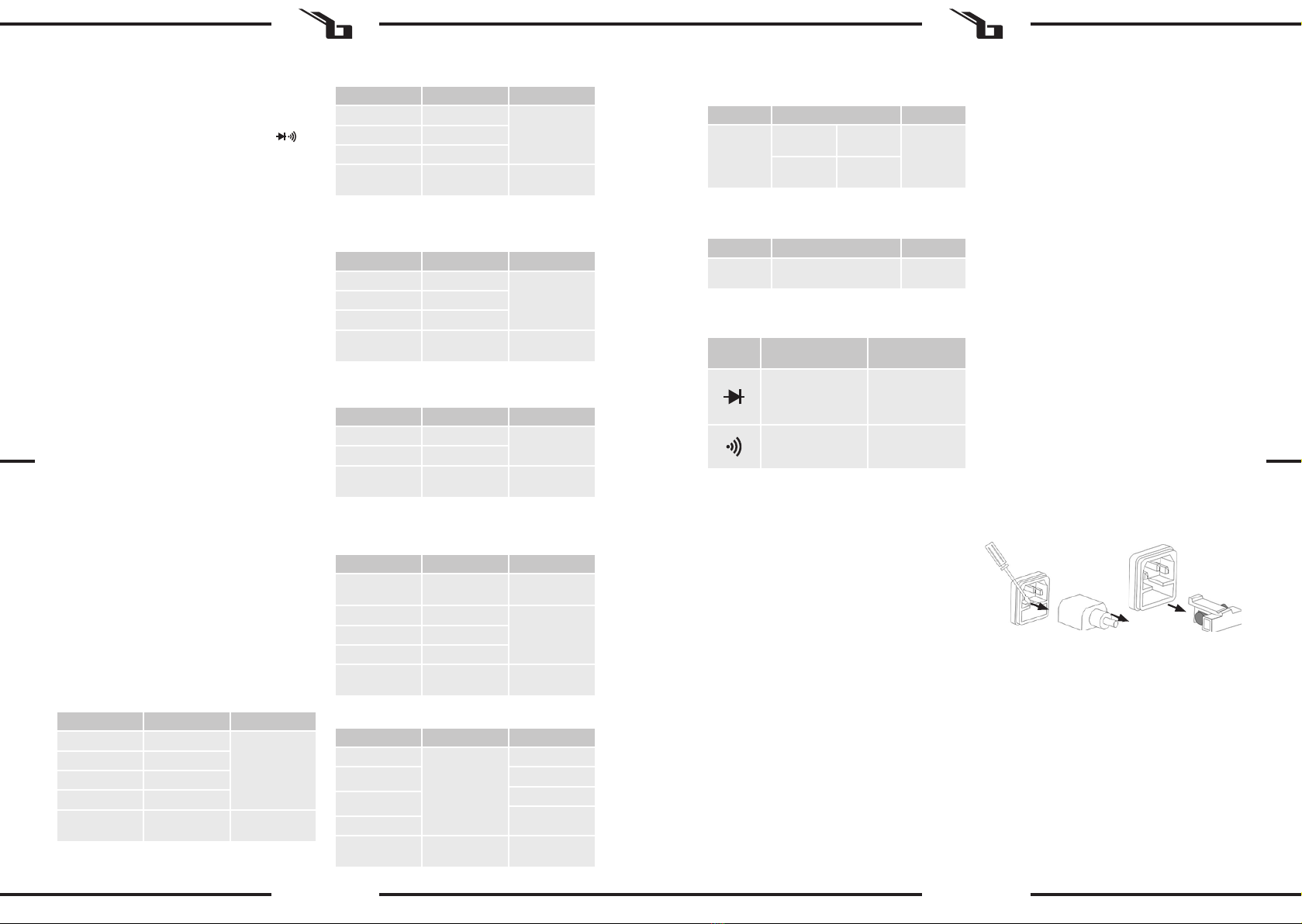
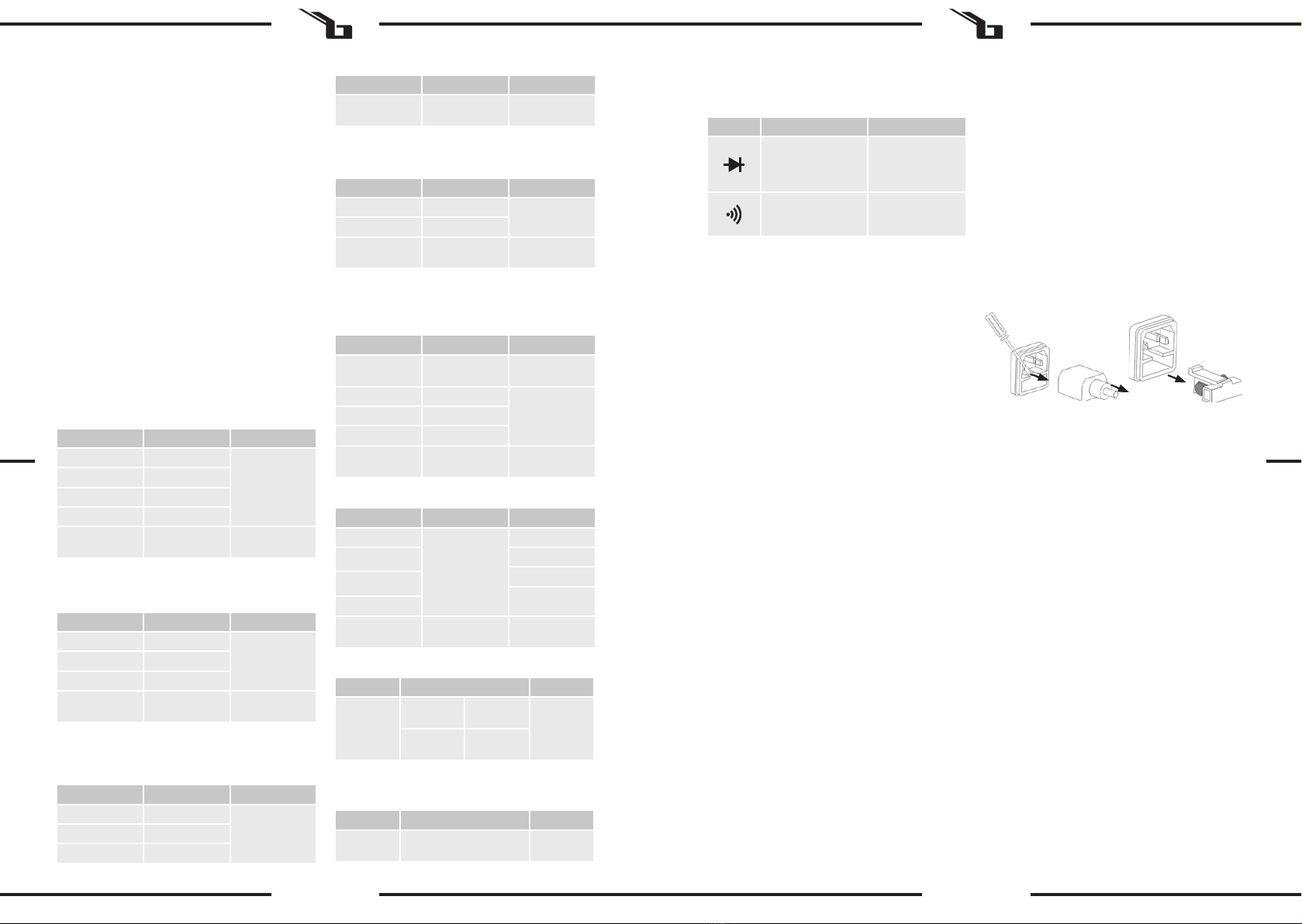
3.3.9. TESTOWANIE DIODY I DŹWIĘKU
a) Ustawić pokrętło w pozycji
b) Podłączyć czarną sondę do gniazda COMT a
czerwoną do gniazda VΩHz
c) Podłączyć sondy pomiarowe do mierzonej diody, na
wyświetlaczu wyświetli się wartość napięcia
d) Podczas testowania sygnału dźwiękowego podłączyć
sondy testowe do dwóch punktów obwodu. Jeśli
opór obwodu jest mniejszy niż 50 Ω urządzenie wyda
z siebie sygnał dźwiękowy.
• Podczas testu upewnij się że obwód jest
odłączony od źródła zasilania oraz, że wszystkie
kondensatory są rozładowane
3.3.10. TESTOWANIE TRANZYSTORA HFE
a) Ustawić pokrętło w pozycji „hFE”
b) Określić czy jest to tranzystor NPN czy PNP i
zlokalizować przewody emitera, bazy i kolektora.
PL
W przypadku gdy, naklejki są nieczytelne należy je
wymienić.
i) Zachować instrukcję użytkowania w celu jej
późniejszego użycia. W razie, gdyby urządzenie miało
zostać przekazane osobom trzecim, to wraz z nim
należy przekazać również instrukcję użytkowania.
PAMIĘTAJ! Należy chronić dzieci i inne osoby
postronne podczas pracy urządzeniem.
2.3. BEZPIECZEŃSTWO OSOBISTE
a) Niedozwolone jest obsługiwanie urządzenia
w stanie zmęczenia, choroby, pod wpływem alkoholu,
narkotyków lub leków, które ograniczają w istotnym
stopniu zdolności obsługi urządzenia.
b) Urządzenie nie jest przeznaczone do tego, by
było użytkowane przez osoby (w tym dzieci)
o ograniczonych funkcjach psychicznych,
sensorycznych i umysłowych lub nieposiadające
odpowiedniego doświadczenia i/lub wiedzy, chyba że
są one nadzorowane przez osobę odpowiedzialną za
ich bezpieczeństwo lub otrzymały od niej wskazówki
dotyczące tego, jak należy obsługiwać urządzenie.
c) Należy być uważnym, kierować się zdrowym
rozsądkiem podczas pracy urządzeniem. Chwila
nieuwagi podczas pracy, może doprowadzić do
poważnych obrażeń ciała.
d) Aby zapobiegać przypadkowemu uruchomieniu
upewnij się, że przełącznik jest w pozycji wyłączonej
przed podłączeniem do źródła zasilania.
e) Urządzenie nie jest zabawką. Dzieci powinny być
pilnowane, aby nie bawiły się urządzeniem.
2.4. BEZPIECZNE STOSOWANIE URZĄDZENIA
a) Nie należy używać urządzenia, jeśli przełącznik ON/
OFF nie działa sprawnie (nie załącza i nie wyłącza
się). Urządzenia, które nie mogą być kontrolowane
za pomocą przełącznika są niebezpieczne, nie mogą
pracować i muszą zostać naprawione.
b) Nieużywane urządzenia należy przechowywać
w miejscu niedostępnym dla dzieci oraz osób
nieznających urządzenia lub tej instrukcji
obsługi. Urządzenia są niebezpieczne w rękach
niedoświadczonych użytkowników.
c) Utrzymywać urządzenie w dobrym stanie
technicznym.
d) Urządzenie należy chronić przed dziećmi.
e) Naprawa oraz konserwacja urządzeń powinna być
wykonywana przez wykwalikowane osoby przy
użyciu wyłącznie oryginalnych części zamiennych.
Zapewni to bezpieczeństwo użytkowania.
f) Aby zapewnić zaprojektowaną integralność
operacyjną urządzenia, nie należy usuwać
zainstalowanych fabrycznie osłon lub odkręcać śrub.
g) Zabrania się przesuwania, przestawiania i obracania
urządzenia będącego w trakcie pracy.
h) Nie należy pozostawiać włączonego urządzenia bez
nadzoru.
i) Należy regularnie czyścić urządzenie, aby nie
dopuścić do trwałego osadzenia się zanieczyszczeń.
j) Urządzenie nie jest zabawką. Czyszczenie
i konserwacja nie mogą być wykonywane przez dzieci
bez nadzoru osoby dorosłej.
k) Nigdy nie mierzyć wartości napięcia, gdy przewody
pomiarowe są podłączone do gniazd pomiarowych
wartości natężenia prądu.
l) Zachować ostrożność podczas pracy przy napięciu
powyżej DC60V lub AC42V.
m) Podczas wykonywania pomiaru trzymać przewody
pomiarowe lub sondy za izolowane części.
n) Wybrać odpowiednią funkcję i zakres pomiarowy dla
pomiaru, aby uniknąć uszkodzenia miernika.
o) Odłączyć przewody pomiarowe od punktów
testowych przed przejściem do innej funkcji.

16 17
09.07.2019
Napięcie DC
Napięcie AC
Natężenie AC
Opór
Pojemnośc
Natężenie DC
Rdg – odczyt. Dgt - cyfra
Impendencja: 10MΩ
Ochrona przeciążeniowa: 1000V DC or 750V AC rms
Ochrona przeciążeniowa: 200mA/500V & 20A/500V Szybki
bezpiecznik. Ważne: 20A do 10 sekund
Impendencja: 10MΩ (2V range is 1MΩ)
Ochrona przeciążeniowa: 1000V DC or 750 AC rms
Zakres częstotliwości: 40 to 400Hz
NiCr-NiSi K-typ czujnika
Ochrona przeciążeniowa: 200mA/500V Szybki bezpiecznik
Ochrona przeciążeniowa: 200mA/500V & 20A/500V Szybki
bezpiecznik
Ważne: 20A do 10 sekund
Zakres częstotliwości: 40 to 400Hz
Ochrona przeciążeniowa: 500V DC or AC rms
Temperatura
Zakres Pewność Precyzja
200mV 0,1mV
±(0,5% of rdg*
+ 2dgt*)
2V 1mV
20V 10mV
200V 100mV
1000V 1V ±(0,8% of rdg
+ 2dgt)
Zakres Pewność Precyzja
2V 1mV
±(1,0% of rdg
+ 2dgt)
20V 10mV
200V 100mV
750V 1V ±(1,2% of rdg
+ 3dgt)
Zakres Pewność Precyzja
2mA 1μA ±(1,5% of rdg
+ 3dgt)
200mA 100μA
20A 10mA ±(2,5% of rdg
+ 5dgt)
Zakres Pewność Precyzja
200Ω 0.1Ω ±(1,0% of rdg
+ 3 dgt)
2kΩ 1Ω
±(1,0% of rdg
+ 2 dgt)
20kΩ 10Ω
200kΩ 100Ω
20MΩ 10kΩ ±(1,5% of rdg
+ 3 dgt)
Zakres Pewność Precyzja
2nF
±(2.5% of rdg +
5 dgt)
1pF
20nF 10pF
100pF
200nF
1nF
2µF
200µF ±(5.0% of rdg +
10 dgt) 100nF
Zakres Pewność Precyzja
°C
-20~150°C ± (3°C
+ 1digit) 1°C
150~1000°C ± (3% of rdg
+ 2dgt)
Zakres Pewność Precyzja
2mA 1μA
±(1,2% of rdg
+ 2dgt)
20mA 10μA
200mA 100μA
Umieścić przewody w odpowiednich otworach
przedniego panelu
c) Zmierzona wartość wyświetli się na ekranie
• nie podłączać zewnętrznego napięcia do
terminala pomiarowego
3.3.11. BEZKONTAKTOWE WYKRYWANIE NAPIĘCIE AC
a) Wcisnąć i przytrzymać przycisk „NCV” miernik
wejdzie w tryb pomiaru bezkontaktowego. Zielona
dioda zaświeci się.
b) Wypośrodkować urządzenie a następnie wycelować
w testowany obwód.
c) Jeśli napięcie obwodu nie przekracza lub jest równe
90 V AC rms to zapali się czerwona i zielona lampka i
pojawi się sygnał dźwiękowy.
d) Aby wyjść z trybu NCV należy puścić przycisk „NCV”
UWAGA: Należy zachować ostrożność podczas
określania obecności napięcia elektrycznego z
wykorzystaniem funkcji pomiaru bezkontaktowego,
aby uniknąć porażenia prądem. Jeśli multimetr nie
wykryje napięcia elektrycznego, to napięcie nadal
może być obecne. Nie należy polegać na funkcji NCV
podczas determinowania obecności przewodów pod
napięciem.
• Podczas użytkowania multimetru w trybie NCV,
należy unikać obecności wszelkiego rodzaju
zakłóceń elektrycznych
3.4 SPECYFIKACJE
Czułość: sinusoida 1V rms
Szybki bezpiecznik: 500V DC or AC rms
Częstotliwość
Zakres Pewność Precyzja
200kHz ± (2,0% of rdg + 5 dgt) 100Hz
PL
Ochrona przeciążeniowa: 200mA/500V Szybki bezpiecznik
Testowanie diody i dźwięku
Ochrona przeciążeniowa: 500V DC or AC rms
Testowanie tranzystora hFE
Zakres testu: 0-1000
Ib=10µA, Vce=3,0V około. 6-11
Bezkontaktowe wykrywanie napięcie AC
Test zakres napięcia: 90V~1000V AC rms
3.5 CZYSZCZENIE I KONSERWACJA
a) Do czyszczenia powierzchni należy stosować
wyłącznie środki niezawierające substancji żrących.
b) Po każdym czyszczeniu wszystkie elementy należy
dobrze wysuszyć, zanim urządzenie zostanie
ponownie użyte.
c) Urządzenie należy przechowywać w suchym
i chłodnym miejscu chronionym przed wilgocią
i bezpośrednim promieniowaniem słonecznym.
d) Zabrania się spryskiwania urządzenia strumieniem
wody lub zanurzania urządzenia w wodzie.
e) Należy wykonywać regularne przeglądy urządzenia
pod kątem jego sprawności technicznej oraz
wszelkich uszkodzeń.
f) Do czyszczenia należy używać miękkiej ściereczki.
g) Nie pozostawiać baterii w urządzeniu, gdy nie będzie
ono używane przez dłuższy czas.
h) Chronić urządzenie przed wilgocią. Jeśli zmoknie,
należy natychmiast wytrzeć do sucha. Płyny mogą
zawierać minerały, które mogą powodować korozję
obwodów elektronicznych.
i) Używać i przechowywać urządzenie w standardowych
warunkach temperaturowych. Ekstremalne
temperatury mogą skrócić żywotność urządzenia,
uszkodzić baterie i zniekształcić lub stopić plastikowe
części.
j) Z urządzeniem należy obchodzić się delikatnie
i ostrożnie. Upuszczenie może uszkodzić płytki
drukowane i spowodować niewłaściwe działanie
urządzenia.
k) Urządzenie chronić przed działaniem kurzu i brudu.
l) Należy używać tylko nowych baterii o rozmiarze
i typie wskazanym w parametrach technicznych.
Przed rozpoczęciem montażu lub wymiany baterii
upewnić się, że urządzenie nie jest podłączone do
zewnętrznego obwodu oraz że pokrętło regulacji
ustawione jest w pozycji „OFF” a przewody
pomiarowe są odłączone od zacisków.
INSTRUKCJA BEZPIECZNEGO USUNIĘCIA AKUMULATORÓW
I BATERII.
W urządzeniach zamontowane są baterie AA 1,5V. Zużyte
baterie należy zdemontować z urządzenia postępując
analogicznie do ich montażu. Baterie przekazać komórce
odpowiedzialnej za utylizację tych materiałów.
Zakres Opis Warunki testowania
Odczyt wyświetlony
w przybliżeniu,
zaokrąglony do góry
Prąd stały DC
ok. 1mA
Prąd zmienny DC
ok. 3V
Dźwięk zabrzmi
jeśli oporność nie
przekroczy 50 Ω
Napięcie w
obwodzie otwartym
ok. 3V
3. Wymienić bezpiecznik na nowy, o takich samych
parametrach.
4. Ponownie zamontować gniazdo bezpiecznika.
UWAGA! Aby uniknąć uszkodzenia gniazda
bezpiecznika, nie wolno używać nadmiernej siły przy
wyciąganiu i montażu gniazda bezpiecznika
PL
Zakres Pewność Precyzja
20A 10mA ±(2,0% of rdg
+ 3dgt)
USUWANIE ZUŻYTYCH URZĄDZEŃ.
Po zakończeniu okresu użytkowania nie wolno usuwać
niniejszegoproduktupoprzeznormalneodpadykomunalne,
lecz należy go oddać do punktu zbiórki i recyklingu
urządzeń elektrycznych i elektronicznych. Informuje o tym
symbol, umieszczony na produkcie, instrukcji obsługi lub
opakowaniu. Zastosowane w urządzeniu tworzywa nadają
się do powtórnego użycia zgodnie z ich oznaczeniem.
Dzięki powtórnemu użyciu, wykorzystaniu materiałów lub
innym formom wykorzystania zużytych urządzeń wnoszą
Państwo istotny wkład w ochronę naszego środowiska.
Informacji o właściwym punkcie usuwania zużytych
urządzeń udzieli Państwu lokalna administracja.
WYMIANA BEZPIECZNIKA:
UWAGA! Wymianę bezpiecznika powinien wykonać
specjalista.
1. Odłączyć urządzenie do zasilania.
2. Odłączyć przewód zasilający i wyjąć gniazdo
bezpiecznika.

18 19
09.07.2019
CZ
Popis parametru Hodnota parametru
Název výrobku Multimetr
Model SBS-DM-1000NCV
Typ baterie 9V (6F22)/ NEDA 1604
Stupeň ochrany IP CAT III 1000V
Přepěťová ochrana 200mV~1000V/ 2V~750V
Rozsah měření střídavého
a stejnosměrného napětí
2mA~20A/2mA~20A
Rozsah měření střídavého
a stejnosměrného proudu
200Ω~20MΩ/
2nF~200uF
Rozsah měření odporu/
elektrické kapacity
-20~1000°C/200kHz
TECHNICKÉ ÚDAJE Zařízení nepoužívejte v prostředí s velmi vysokou vlhkostí /
v přímé blízkosti nádrží s vodou! Zařízení nenořte do vody.
Hrozí nebezpečí úrazu elektrickým proudem! Nezakrývejte
větrací otvory!
2.1. ELEKTRICKÁ BEZPEČNOST
a) Daná zásuvka musí být se zástrčkou zařízení
kompatibilní. Zástrčku žádným způsobem
neupravujte. Originální zástrčky a příslušné zásuvky
snižují nebezpečí úrazu elektrickým proudem.
b) Nedotýkejte se uzemněných předmětů jako jsou
trubky, topidla, kamna a chladničky. Pokud je
zařízení uzemněno, existuje zvýšené nebezpečí
úrazu elektrickým proudem v následku působení
deště, mokrého povrchu a práce se zařízením ve
vlhkém prostředí. Proniknutí vody do zařízení zvyšuje
nebezpečí jeho poškození a úrazu elektrickým
proudem.
c) Zařízení se nedotýkejte mokrýma nebo vlhkýma
rukama.
d) Napájecí kabel nepoužívejte na jiné účely, než na
které je určen. Nikdy jej nepoužívejte k přenášení
zařízení nebo k vytahování zástrčky ze síťové zásuvky.
Držte jej mimo dosah tepla, oleje, ostrých hran nebo
rotujících dílů. Poškozené nebo zamotané elektrické
napájecí kabely zvyšují nebezpečí úrazu elektrickým
proudem.
e) Pokud není možné vyhnout se práci se zařízením
ve vlhkém prostředí, používejte při tom proudový
chránič (RCD). Používání RCD snižuje nebezpečí
úrazu elektrickým proudem.
2.2. BEZPEČNOST NA PRACOVIŠTI
a) Na pracovišti udržujte pořádek a mějte dobré
osvětlení. Nepořádek nebo špatné osvětlení mohou
vést k úrazům. Buďte předvídaví a sledujte, co se
během práce kolem vás děje. Při práci se zařízením
vždy zachovávejte zdravý rozum.
b) Se zařízením nepracujte ve výbušném prostředí,
například v přítomnosti hořlavých kapalin, plynů
nebo prachu. Zařízení vytváří jiskření, skrze které
může dojít ke vznícení prachu nebo výparů.
c) Pokud zjistíte, že zařízení nepracuje správně, nebo
je poškozeno, ihned jej vypněte a poruchu nahlaste
autorizované osobě.
d) Pokud máte pochybnosti o tom, zda zařízení funguje
správně, kontaktujte servis výrobce.
e) Opravy zařízení může provádět pouze servis výrobce.
Opravy neprovádějte sami!
f) V případě vzniku požáru k hašení zařízení pod
napětím používejte pouze práškové nebo sněhové
hasicí přístroje (CO2).
g) Na pracovišti se nesmí zdržovat děti a nepovolané
osoby. (Nepozornost může způsobit ztrátu kontroly
nad zařízením.)
h) Je třeba pravidelně kontrolovat stav etiket s
bezpečnostními informacemi. V případě, že jsou
nečitelné, je třeba etikety vyměnit.
i) Návod k obsluze uschovejte za účelem jeho
pozdějšího použití. V případě předánání zařízení
třetím osobám musí být spolu se zařízením předán
rovněž návod k obsluze.
NÁVOD K POUŽITÍ
1. VŠEOBECNÝ POPIS
Návod slouží jako nápověda pro bezpečné a spolehlivé
používání výrobku. Výrobek je navržen a vyroben přesně
podle technických údajů za použití nejnovějších technologií
a komponentů a za dodržení nejvyšších jakostních norem.
PŘED ZAHÁJENÍM PRÁCE SI DŮKLADNĚ PŘEČTĚTE
TENTO NÁVOD A UJISTĚTE SE, ŽE JSTE POCHOPILI
VŠECHNY POKYNY.
Pro zajištění dlouhého a spolehlivého fungování zařízení
pravidelně provádějte revize a údržbu v souladu s pokyny
uvedenými v tomto návodu. Technické údaje a specikace
uvedené v návodu jsou aktuální. Výrobce si vyhrazuje právo
provádět změny za účelem zvýšení kvality.
2. BEZPEČNOST POUŽÍVÁNÍ
POZNÁMKA! Přečtěte si tento návod včetně všech
bezpečnostních pokynů. Nedodržování návodu a
pokynů může vést k úrazu elektrickým proudem,
požáru anebo těžkému úrazu či smrti.
Originálním návodem je německá verze návodu. Ostatní
jazykové verze jsou překladem z německého jazyka.
Pojem „zařízení“ nebo „výrobek“ v bezpečnostních
pokynech a návodu se vztahuje na < Multimetr >.
POZOR! Obrázky v tomto návodu jsou pouze
ilustrační a v některých detailech se od skutečného
vzhledu výrobku mohou lišit.
VYSVĚTLENÍ SYMBOLŮ
Výrobek splňuje požadavky příslušných
bezpečnostních norem.
Před použitím výrobku se seznamte s návodem.
Recyklovatelný výrobek.
UPOZORNĚNÍ! nebo VAROVÁNÍ! nebo
PAMATUJTE! popisující danou situaci.
(všeobecná výstražná značka).
VAROVÁNÍ! Nebezpečí úrazu elektrickým
proudem!
Zařízení s druhou třídou ochrany a dvojitou
izolací.
PAMATUJTE! Při práci se zařízením chraňte děti a
jiné nepovolané osoby.
POZNÁMKA! I když zařízení bylo navrženo tak, aby
bylo bezpečné, tedy má vhodné bezpečnostní prvky,
tak i přes použití dodatečné ochrany uživatelem při
práci se zařízením nadále existuje malé riziko úrazu
nebo poranění. Doporučuje se zachovat opatrnost a
zdravý rozum při jeho používání.
3. ZÁSADY POUŽÍVÁNÍ
Digitální multimetr je určen k měření elektrických hodnot
vybraných zařízení a elektrických obvodů.
Odpovědnost za veškeré škody vzniklé v důsledku
použití zařízení v rozporu s určením nese uživatel.
3.1. POPIS ZAŘÍZEN
3.2. PŘÍPRAVA K PRÁCI
Okolní teplota by se měla pohybovat v rozsahu od 18 °C
do 28 °C (od 64 °F do 82 °F) a relativní vlhkost vzduchu
by neměla být vyšší než 70 %. Zařízení postavte takovým
způsobem, aby byla zajištěna dobrá cirkulace vzduchu.
Vzdálenost zařízení od stěny by neměla být menší než
10 cm. Zařízení se musí nacházet daleko od jakéhokoli
horkého povrchu. Zařízení musí být vždy používáno
na rovném, stabilním, čistém, žáruvzdorném a suchém
povrchu a mimo dosah dětí a osob s mentálním postižením.
Zařízení umístěte takovým způsobem, abyste v každém
okamžiku měli ničím nezatarasený přístup k elektrické
zásuvce. Ujistěte se, aby hodnoty proudu, kterým je zařízení
napájeno, byly shodné s údaji uvedenými na technickém
štítku zařízení!.
3.3. PRÁCE S PŘÍSTROJEM
UPOZORNĚNÍ: SYMBOLY a popisy umístěné u zdířek
označují hodnoty napětí a elektrického proudu, které nesmí
být překročeny, jelikož jejich překročení může způsobit
ztrátu na životě nebo ohrozit zdraví a poškodit multimetr.
UPOZORNĚNÍ: Před zahájením měření se ujistěte, že
otočný přepínač – výběr funkce a rozsahu měření – je
nastaven na správný rozsah měření.
UPOZORNĚNÍ: Pokud si nejste jisti, jaký rozsah zvolit pro
měřený proud, nastavte přepínač rozsahu na největší
rozsah.
UPOZORNĚNÍ: pokud se na displeji zobrazí číslice 1 nebo
-1, znamená to, že naměřená hodnota je mimo stupnici
zvoleného rozsahu. Je třeba tedy zvýšit rozsah a provést
opětovné měření.
UPOZORNĚNÍ: V případě, že se na displeji přístroje objeví
informace o vybití baterie a nutnosti její výměny za novou.
3.3.1. MĚŘENÍ NAPĚTÍ STEJNOSMĚRNÉHO PROUDU
a) Nastavte otočný přepínač do polohy V .
POZNÁMKA! Nákres tohoto produktu naleznete na
konci návodu na str. 38.
1. Detektor napětí (NCV)
2. CDS senzor
3. Červená dioda: detekce napětí
4. Zelená dioda: detekce napětí
5. LCD displej.
6. Tlačítko POWER zapne nebo vypne zařízení.
7. Tlačítko D.HOLD/Podsvícení: Blokování/odblokování
zobrazené hodnoty.
8. Tlačítko NCV, zapnutí (zelená kontrolka) /vypnutí
režimu bezkontaktního měření
9. Regulátor: volba funkce a rozsahu měření
10. Vstupní zdířka: mA T+, používaná při měření
kondenzátoru, mA a teploty „+“.
11. Vstupní zásuvka: 20A.
12. Vstupní zásuvka: Ω VΩHz: V / 200kHz.
13. Vstupní zásuvka: T COMT-: COM a teplota „-“.
14. Vstupní zásuvka: hFE
2.3. OSOBNÍ BEZPEČNOST
a) Zařízení nepoužívejte, jste-li unaveni nebo pod
vlivem drog, alkoholu nebo léků, které významně
snižují schopnost zařízení ovládat.
b) Zařízení není určen k tomu, aby jej používaly osoby
(včetně dětí) s omezenými psychickými, smyslovými
nebo duševními schopnostmi nebo osoby bez
příslušných zkušeností a/nebo znalostí, ledaže
jsou pod dohledem osoby zodpovědné za jejich
bezpečnost nebo od ní obdržely pokyny, jak zařízení
obsluhovat.
c) Při práci se zařízením buďte pozorní, řiďte se zdravým
rozumem. Chvilka nepozornosti při práci může vést k
vážnému úrazu.
d) Zabraňte náhodnému spuštění. Ujistěte se, že je
spínač ve vypnuté poloze před připojením zařízení k
napájecímu zdroji.
e) Zařízení není hračka. Dohlížejte na děti, aby si nehrály
se zařízením.
2.4. BEZPEČNÉ POUŽÍVÁNÍ ZAŘÍZENÍ
a) Zařízení nepoužívejte, pokud spínač pro zapnutí a
vypnutí zařízení nefunguje správně. Zařízení, které
nelze ovládat spínačem, je nebezpečné a musí být
opraveno.
b) Nepoužívaná zařízení uchovávejte mimo dosah dětí
a osob, které nejsou seznámeny se zařízením nebo
návodem k obsluze. Zařízení jsou nebezpečná v
rukou nezkušených uživatelů.
c) Zařízení udržujte v dobrém technickém stavu.
d) Udržujte zařízení mimo dosah dětí.
e) Opravu a údržbu zařízení by měly provádět
pouze kvalikované osoby za výhradního použití
originálních náhradních dílů. Zajistí to bezpečné
používání zařízení.
f) Pro zachování navržené mechanické integrity zařízení
neodstraňujte předem namontované kryty nebo
neuvolňujte šrouby.
g) Nepřesouvejte, nepřenášejte a neotáčejte zařízení v
provozu.
h) Zapnuté zařízení nenechávejte bez dozoru.
i) Pravidelně čistěte zařízení, aby nedošlo k trvalému
usazovaní nečistot.
j) Zařízení není hračka. Čištění a údržbu nesmí provádět
děti bez dohledu dospělé osoby.
k) Nikdy neměřte hodnoty napětí, jestliže měřící
kabely jsou zapojené do testovacích zdířek hodnoty
elektrického proudu.
l) Při práci s napětím vyšším než DC60V nebo AC42V
buďte velmi opatrní.
m) Při měření držte testovací kabely nebo sondy za
izolované části.
n) Vyberte příslušnou funkci a měřící rozsah, aby
nedošlo k poškození měřícího přístroje.
o) Odpojte měřící kabely od testovacích bodů před
přechodem do jiné funkce.
CZ

20 21
09.07.2019
Napětí DC
Napětí AC
Elektrický proud AC
Odpor
Kapacita
Elektrický proud DC
Rdg – měřená hodnota. Dgt – číslice
Vstupní impedance: 10MΩ
Přepěťová ochrana: 1000V DC or 750V AC rms
Přepěťová ochrana: 200mA/500V & 20A/500V Rychlá
pojistka. Důležité: 20 A do 10 sekund
Vstupní impedance: 10MΩ
Přepěťová ochrana: 1000V DC or 750 AC rms
Frekvence rozsahu: 40 to 400Hz
NiCr-NiSi K-typ termočlánku
Přepěťová ochrana: 200mA/500V pojistka
Přepěťová ochrana: 200mA/500V & 20A/500V pojistka
Důležité: 20 A do 10 sekund
Frekvence rozsahu: 40 to 400Hz
Přepěťová ochrana: 500V DC or AC rms
Teplota
Rozsah Napájení Přesnost
200mV 0,1mV
±(0,5% of rdg*
+ 2dgt*)
2V 1mV
20V 10mV
200V 100mV
1000V 1V ±(0,8% of rdg
+ 2dgt)
Rozsah Napájení Přesnost
2V 1mV
±(1,0% of rdg
+ 2dgt)
20V 10mV
200V 100mV
750V 1V ±(1,2% of rdg
+ 3dgt)
Rozsah Napájení Přesnost
2mA 1μA ±(1,5% of rdg
+ 3dgt)
200mA 100μA
20A 10mA ±(2,5% of rdg
+ 5dgt)
Rozsah Napájení Přesnost
200Ω 0.1Ω ±(1,0% of rdg
+ 3 dgt)
Rozsah Napájení Přesnost
2nF
±(2.5% of rdg +
5 dgt)
1pF
20nF 10pF
100pF
200nF
1nF
2µF
200µF ±(5.0% of rdg +
10 dgt) 100nF
Rozsah Napájení Přesnost
°C
-20~150°C ± (3°C
+ 1digit) 1°C
150~1000°C ± (3% of rdg
+ 2dgt)
Rozsah Napájení Přesnost
2mA 1μA ±(1,2% of rdg
+ 2dgt)
20mA 10μA
200mA 100μA ±(1,2% of rdg
+ 2dgt)
20A 10mA ±(2,0% of rdg
+ 3dgt) Citlivost: sinusoida1V rms, pojistka: 500V DC or AC rms
Frekvence
Rozsah Napájení Přesnost
200kHz ± (2,0% of rdg + 5 dgt) 100Hz
CZ
Přepěťová ochrana: 200mA/500V pojistka
Rozsah Napájení Přesnost
2kΩ 1Ω
±(1,0% of rdg
+ 2 dgt)
20kΩ 10Ω
200kΩ 100Ω
20MΩ 10kΩ ±(1,5% of rdg
+ 3 dgt)
Test diod a kontinuity
Přepěťová ochrana: 500V DC or AC rms
Měření proudového zesilovacího činitele tranzistoru hFE
Rozsah testu: 0-1000
Ib=10µA, Vce=3.0V přibližně
6-11 Bezkontaktní detekce napětí střídavého proudu
Test rozsahu napětí: 90V~1000V AC rms
Rozsah Popis Podmínky testování
Hodnota je orientační,
je zaokrouhlena
nahoru
Stejnosměrný proud
DC cca 1 mA.
Střídavý proud DC
cca 3 V
Zvukový signál zazní
v případě, nebude-li
odpor vyšší než 50 Ω
Napětí v otevřeném
obvodu cca 3 V
3.5 ČIŠTĚNÍ A ÚDRŽBA
a) K čištění povrchu zařízení používejte výhradně
prostředky neobsahující žíravé látky.
b) Po každém čištění je nutno všechny prvky dobře
osušit, než bude zařízení opět použito.
CZ
b) Zapojte černý měřicí kabel do zdířky COMT a červený
do zdířky VΩHz.
c) Přiložte měřicí sondy k testovanému obvodu.
d) Naměřená hodnota se zobrazí na LCD displeji.
Bude zobrazena polarita červeného vodiče spolu s
hodnotou napětí DC.
3.3.2. MĚŘENÍ NAPĚTÍ STŘÍDAVÉHO PROUDU
a) Nastavte otočný přepínač do polohy V~.
b) Zapojte černý měřicí kabel do zdířky COMT a červený
do zdířky VΩHz.
c) Přiložte k testovanému obvodu obě sondy.
d) Na LCD displeji se zobrazí naměřená hodnota.
• Symbol „ ” značí, že není možné přesáhnout
hodnotu napětí 750 V, jinak by mohlo dojít k
poškození přístroje.
3.3.3. MĚŘENÍ STEJNOSMĚRNÉHO PROUDU
a) Nastavte otočný přepínač do polohy A .
b) Zapojte černý měřicí kabel do zdířky COMT a červený
do mAT+ pro maximální měření v rozsahu 200 mA.
Pro měření proudu v rozsahu od 200 mA do 20 A
zapojte červený vodič do zdířky 20 A.
c) Přiložte obě sondy k testovanému obvodu.
d) Na LCD displeji se zobrazí naměřená hodnota.
Zobrazí se polarita červené sondy včetně hodnoty
proudu.
• Symbol značí, že maximální hodnota
měřeného proudu ve zdířce nesmí překročit
hodnotu 200 mA.
• Měření v rozsahu 20 A by nemělo trvat déle než
10 s, zmenší se tím riziko přehřátí kabelů.
3.3.4. MĚŘENÍ STŘÍDAVÉHO PROUDU
a) Nastavte otočný přepínač do polohy A~.
b) Pro měření v maximálním rozsahu 200 mA zapojte
černou měřicí sondu do zdířky COMT a červenou do
mAT+. Pro měření v rozsahu od 200 mA do 20 A je
třeba červený kabel zapojit do zdířky 20 A.
c) Přiložte obě sondy k testovanému obvodu.
d) Na LCD displeji se zobrazí naměřená hodnota.
• Symbol upozorňuje, že hodnota měřeného
proudu ve zdířce nesmí být vyšší než maximálně
200 mA.
• Měření při použití zdířky 20 A by nemělo trvat
déle než 10 s, zmenší se tím riziko přehřátí
obvodu.
3.3.5. MĚŘENÍ ODPORU
a) Nastavte otočný přepínač do polohy Ω.
b) Zapojte černou sondu do zdířky COMT a červenou
do zdířky VΩHz.
c) Přiložte obě sondy k testovanému obvodu.
d) Na LCD displeji se zobrazí naměřená hodnota.
• Maximální odečet je 500 V rms < 10 s.
• Upozornění: Pokud se na displeji zobrazí číslice
1 nebo -1, znamená to, že naměřená hodnota je
mimo stupnici zvoleného rozsahu. Je tedy třeba
zvýšit měřený rozsah a zopakovat měření.
• Pro změření odporu vyššího než 10 M Ω bude
multimetr potřebovat nějakou dobu, aby
stabilizoval odečet.
• Pokud je obvod otevřený, multimetr zobrazí
hodnotu „1“ nebo „-1“.
• Během měření se ujistěte, že je obvod odpojený
od zdroje napájení a že všechny kondenzátory
jsou vybité.
3.3.6. MĚŘENÍ KAPACITY
a) Nastavte otočný přepínač do polohy „F°“.
b) Zapojte černou sondu do zdířky COMT a červenou
do zdířky mAT+.
c) Přiložte obě sondy k testovanému obvodu.
d) Na displeji se zobrazí naměřená hodnota.
• Před měřením kapacity by měly být všechny
kondenzátory vybité.
3.3.7. MĚŘENÍ TEPLOTY
a) Nastavte otočný přepínač do polohy “°C ”.
b) Zapojte černou sondu do zdířky COMT a červenou
do zdířky mAT+.
c) Dotkněte se sondou povrchu, kde má být teplota
změřena.
d) Na LCD displeji se zobrazí naměřená hodnota.
• Limit měření termočlánku je 250 °C. K měření
vyšších teplot je třeba použít měřicí sondu
určenou pro vyšší teplotní rozsah.
• Během měření teploty buďte důslední.
3.3.8. MĚŘENÍ FREKVENCE
a) Nastavte otočný přepínač do polohy 200 kHz.
b) Zapojte černou sondu do zdířky COMT a červenou
do zdířky VΩHz.
c) Přiložte obě sondy k testovanému obvodu.
d) Na displeji se zobrazí naměřená hodnota.
3.3.9. TEST DIOD A KONTINUITY
a) Nastavte otočný přepínač do polohy
b) Zapojte černou sondu do zdířky COMT a červenou
do zdířky VΩHz.
c) Připojte měřicí sondy k měřené diodě, na displeji
se zobrazí hodnota napětí této diody zaokrouhlena
směrem nahoru.
d) Pro test kontinuity obvodu připojte měřící sondy ke
• dvěma bodům obvodu. Pokud je odpor obvodu
menší než 50Ω zařízení vydá zvukový signál.
• Během testu se ujistěte, že je obvod odpojen
od zdroje napájení a že všechny kondenzátory
jsou vybité.
3.3.10. MĚŘENÍ PROUDOVÉHO ZESILOVACÍHO ČINITELE
TRANZISTORU HFE
a) Nastavte otočný přepínač do polohy „hFE“.
b) Zjistěte, zda se jedná o tranzistor NPN, nebo PNP,
a vyhledejte vodiče vysílače, základny a kolektoru.
Zapojte vodiče do příslušných otvorů na předním
panelu.
c) Na displeji se zobrazí naměřená hodnota.
• Nepřipojujte k měřící svorce externí napětí.
3.3.11. BEZKONTAKTNÍ DETEKCE NAPĚTÍ STŘÍDAVÉHO
PROUDU
a) Stiskněte a přidržte tlačítko „NCV“, měřicí přístroj
přejde do bezkontaktního režimu. Rozsvítí se zelená
dioda.
b) Vycentrujte přístroj a pak zaměřte na testovaný
obvod.
c) Pokud napětí obvodu není vyšší než nebo se rovná
90 V AC rms, rozsvítí se červená i zelená dioda a ozve
se zvukový signál.
d) Pro opuštění režimu NCV je třeba uvolnit tlačítko „NCV“.
UPOZORNĚNÍ: Při zjišťování elektrického napětí
bezkontaktní detekcí je třeba dbát maximální
opatrnosti, aby nedošlo k zásahu elektrickým
proudem. I když multimetr napětí nedetekuje, může
být i přesto přítomno. Na funkci NCV se nemůžete
se spoléhat během detekce u vodičů pod napětím.
3.4. SPECIFIKACE
• Při používání multimetru v režimu NCV je třeba se
vyvarovat jakéhokoliv druhu elektrického rušení.

22 23
09.07.2019
Le produit est conforme aux normes de sécurité
en vigueur.
Respectez les consignes du manuel.
Collecte séparée.
ATTENTION! , AVERTISSEMENT! et REMARQUE
attirent l'attention sur des circonstances
spéciques (symboles d'avertissement
généraux).
ATTENTION! Mise en garde liée à la tension
électrique!
Appareil de la classe de protection II possédant
une isolation renforcée.
CZ
c) Zařízení skladujte na suchém a chladném místě,
chráněném proti vlhkosti a přímému slunečnímu
svitu.
d) Je zakázáno zařízení polévat vodou nebo je do vody
ponořovat.
e) Pravidelně provádějte revize zařízení a kontrolujte,
zda je technicky způsobilé a není poškozeno.
f) K čištění používejte měkký hadřík.
g) Pokud zařízení nebudete používat delší dobu,
vytáhněte z něj akumulátor/baterii.
h) Chraňte zařízení před vlhkostí. Pokud zmokne,
ihned jej otřete do sucha. Kapaliny mohou
obsahovat minerály, které mohou způsobit korozi
elektronického obvodu.
i) Zařízení používejte a skladujte za normálních
teplotních podmínek. Extrémní teploty mohou
zkrátit životnost zařízení, poškodit baterie a poškodit
nebo roztavit plastové díly.
j) Se zařízením zacházejte jemně a opatrně. Upuštění
může poškodit desky s plošnými spoji a způsobit
poruchu zařízení.
k) Chraňte zařízení před prachem a nečistotami.
l) Používejte pouze nové baterie, jejichž velikost a typ
je uveden v technických parametrech. Před instalací
nebo výměnou baterií se ujistěte, že zařízení není
připojeno k externímu obvodu, že je přepínač
nastaven do polohy „OFF” a zkušební vodiče jsou
odpojeny od svorek.
NÁVOD K BEZPEČNÉMU ODSTRANĚNÍ AKUMULÁTORŮ A
BATERIÍ.
V zařízení se používají baterie 9V (6F22 / NEDA 1604).
Vybité baterie ze zařízení vyjměte, postupujte v opačném
pořadí než při jejich vkládání. Pro zajištění vhodné likvidace
baterie vyhledejte příslušné místo/obchod, kde je můžete
odevzdat
VÝMĚNA POJISTKY
UPOZORNĚNÍ! Výměnu pojistky by měl provést
kvalikovaný odborník!
1. Odpojte zařízení od zdroje napájení.
2. Odpojte přívodní kabel a vytáhněte zásuvku pojistky.
3. Vyměňte pojistku za novou se stejnými parametry.
4. Opět zasuňte zásuvku s pojistkou.
UPOZORNĚNÍ! Aby nedošlo k poškození zásuvky
s pojistkou, nepoužívejte při vytahování a zpětné
montáži příliš velkou sílu.
Description des
paramètres
Valeur des paramètres
Nom du produit Multimètre
Modèle SBS-DM-1000NCV
Type de pile 9V (6F22)/ NEDA 1604
Classe de protection IP CAT III 1000V
Protection contre les
surtensions
200mV~1000V/ 2V~750V
Plage de mesure de
la tension du courant
continu/courant alternatif
2mA~20A/2mA~20A
Plage de mesure de
l'intensité du courant
continu/courant alternatif
200Ω~20MΩ/
2nF~200uF
Plage de mesure de
résistance/capacité
électrique
-20~1000°C/200kHz
DÉTAILS TECHNIQUES
Les notions d'« appareil », de « machine » et de « produit
» gurant dans les descriptions et les consignes du manuel
se rapportent à/au < Multimètre >. N'utilisez pas l'appareil
dans des pièces où le taux d'humidité est très élevé, ni à
proximité immédiate de récipients d'eau! Ne mouillez pas
l'appareil. Risque de chocs électriques! Ne couvrez pas les
orices de ventilation!
2.1. SÉCURITÉ ÉLECTRIQUE
a) La che de l’appareil doit être compatible avec la
prise électrique. Ne modiez d'aucune façon la che
électrique. L'utilisation de la che originale et d'une
prise électrique adaptée diminue les risques de chocs
électriques.
b) Évitez de toucher aux composants mis à la terre
comme les tuyaux, les radiateurs, les fours et
les réfrigérateurs. Le risque de chocs électriques
augmente lorsque votre corps est mis à la terre par
le biais de surfaces trempées et d'un environnement
humide. La pénétration d'eau dans l'appareil accroît
le risque de dommages et de chocs électriques.
c) Ne touchez pas l'appareil lorsque vos mains sont
humides ou mouillées.
d) N'utilisez pas le câble d'une manière diérant de son
usage prévu. Ne vous en servez jamais pour porter
l'appareil. Ne tirez pas sur le câble pour débrancher
l'appareil. Tenez le câble à l'écart de la chaleur, de
l'huile, des arêtes vives et des pièces mobiles. Les
câbles endommagés ou soudés augmentent le
risque de chocs électriques.
e) Si vous n'avez d'autre choix que de vous servir de
l’appareil dans un environnement humide, utilisez
un dispositif diérentiel à courant résiduel (DDR). Un
DDR réduit le risque de chocs électriques.
2.2. SÉCURITÉ AU POSTE DE TRAVAIL
a) Veillez à ce que votre poste de travail soit toujours
propre et bien éclairé. Le désordre ou un éclairage
insusant peuvent entraîner des accidents. Soyez
prévoyant, observez les opérations et faites preuve
de bon sens lorsque vous utilisez l’appareil.
b) N'utilisez pas l'appareil dans les zones à risque
d'explosion, par exemple à proximité de liquides,
de gaz ou de poussières inammables. Certains
appareils peuvent produire des étincelles
susceptibles d’enammer la poussière et les vapeurs.
c) En cas de dommages ou de mauvais fonctionnement,
l’appareil doit être mis hors tension immédiatement
et la situation doit être rapportée à une personne
compétente.
d) En cas d’incertitude quant au fonctionnement correct
de l’appareil, contactez le service client du fabricant.
e) Seul le service du fabricant peut eectuer des réparations.
Ne tentez aucune réparation par vous-même !
f) En cas de feu ou d’incendie, utilisez uniquement des
extincteurs à poudre ou au dioxyde de carbone (CO2)
pour étouer les ammes sur l’appareil.
MANUEL D´UTILISATION
1. DESCRIPTION GÉNÉRALE
L'objectif du présent manuel est de favoriser une utilisation
sécuritaire et able de l'appareil. Le produit a été conçu
et fabriqué en respectant étroitement les directives
techniques applicables et en utilisant les technologies et
composants les plus modernes. Il est conforme aux normes
de qualité les plus élevées.
LISEZ ATTENTIVEMENT LE PRÉSENT MANUEL ET
ASSUREZ-VOUS DE BIEN LE COMPRENDRE AVANT
LA PREMIÈRE UTILISATION.
An de garantir le fonctionnement able et durable de
l'appareil, il est nécessaire d'utiliser et d'entretenir ce
dernier conformément aux consignes gurant dans le
présent manuel. Les caractéristiques et les spécications
contenues dans ce document sont à jour. Le fabricant se
réserve le droit de procéder à des modications à des ns
d’amélioration du produit.
2. CONSIGNES DE SÉCURITÉ
ATTENTION! Veuillez lire attentivement toutes les
consignes de sécurité et toutes les instructions. Le
non-respect des avertissements et des consignes
de sécurité peut entraîner des chocs électriques, un
incendie, des blessures graves ou la mort.
REMARQUE! Les illustrations contenues dans le
présent manuel sont fournies à titre explicatif. Votre
appareil peut ne pas être identique.
SYMBOLES
FR
La version originale de ce manuel a été rédigée en
allemand. Toutes les autres versions sont des traductions
de l'allemand.

24 25
09.07.2019
Assurez-vous que l’alimentation électrique correspond aux
indications gurant sur la plaque signalétique du produit!.
3.3. TRAVAIL AVEC L'APPAREIL
ATTENTION : Le symbole et la description placés à
côté des bornes d'entrées indiquent le niveau de tension
et de courant à ne pas dépasser, car cela peut entraîner des
blessures, la mort ou endommager le multimètre.
ATTENTION : Avant de commencer la mesure, assurez-
vous que le commutateur de sélection de la fonction et
de la plage de mesure est réglé sur la plage de mesure
correcte.
ATTENTION : Si vous n’êtes pas sûr de la plage de courant
mesurée, réglez le commutateur de plage sur la position
la plus haute.
ATTENTION : Si le chire 1 ou -1 s'ache à l'écran, cela
signie que la valeur mesurée est hors plage. Sélectionnez
une plage supérieure et relancez la mesure.
ATTENTION : Si l'écran de l'appareil indique un niveau de
batterie faible et qu'il est nécessaire de la remplacer par
une nouvelle,
3.3.1 MESURE DE TENSION CC
a) Tournez le commutateur en position V
b) Branchez le cordon de mesure noir à la borne COMT
et le cordon de mesure rouge à la borne VΩHz.
c) Appliquez les sondes de mesure sur le circuit testé.
d) La valeur mesurée s'ache sur l'écran LCD. La
polarité du cordon rouge est indiquée, ainsi que la
valeur de la tension CC.
3.3.2. MESURE DE LA TENSION CA
a) Tournez le commutateur en position V~.
b) Branchez le cordon de mesure noir à la borne COMT
et le cordon de mesure rouge à la borne VΩHz.
c) Touchez le circuit testé avec les deux sondes
d) La valeur mesurée s'ache sur l'écran LCD.
• Signie que vous ne pouvez pas appliquer
une tension supérieure à 750 V, cela peut
endommager l'appareil.
3.3.3. MESURE DE TENSION CC
a) Réglez le commutateur en position A
b) Branchez le cordon de mesure noir à la borne COMT
et le cordon de mesure rouge à la borne mAT+ pour
une mesure maximale dans la plage de 200 mA. Pour
une mesure d'intensité de 200 mA à 20 A, branchez
le cordon rouge à la borne 20 A.
c) Touchez le circuit testé avec les deux sondes.
d) La valeur mesurée s'ache sur l'écran LCD. La
polarité du cordon rouge est achée, ainsi que la
valeur du courant.
• Signie que la mesure maximale de la borne
ne dépassera pas 200 mA
• Les mesures dans la plage de 20 A ne doivent
pas dépasser 10 s, an de réduire le risque de
surchaue des câbles.
3.3.4. MESURE DE TENSION CA
a) Réglez le commutateur en position A~
b) Branchez la sonde de mesure noire à la borne COMT
et la sonde de mesure rouge à la borne mAT+ pour
une mesure maximale dans la plage de 200 mA.
Pour une mesure dans la plage de 200 mA à 20 A,
branchez le cordon rouge à la borne 20 A.
c) Touchez le circuit testé avec les deux sondes
d) La valeur mesurée s'ache sur l'écran LCD.
• Signie que la mesure maximale de la borne
ne dépassera pas 200 mA
• Les mesures lors de l'utilisation de la borne 20
A ne doivent pas dépasser 10 secondes pour
réduire le risque de surchaue du circuit.
3.3.5. MESURE DE RÉSISTANCE
a) Réglez le commutateur en position Ω.
b) Branchez la sonde noire à la borne COMT et la sonde
rouge à la borne VΩHz.
c) Touchez le circuit testé avec les deux sondes
d) la valeur mesurée s'ache sur l'écran LCD.
• La lecture maximale est de 500 V rms <10 sec.
• Attention : Si le chire 1 ou -1 s'ache à l'écran,
cela signie que la valeur mesurée est hors
plage. Sélectionnez une plage supérieure et
relancez la mesure.
• Pour mesurer une résistance au-dessus de 10
MΩ, le multimètre a besoin d'un moment pour
stabiliser la lecture.
• Si le circuit est ouvert, le multimètre ache la
valeur « 1 » ou « -1 ».
• Pendant la mesure, assurez-vous que le circuit
est débranché de la source d'alimentation et
que tous les condensateurs sont déchargés.
3.3.6. MESURE DE CAPACITANCE
a) Réglez le commutateur en position « F°»
b) Branchez la sonde noire à la borne COMT et la sonde
rouge à la borne mAT+
c) Touchez le circuit testé avec les deux sondes
d) La valeur mesurée s'ache sur l'écran.
• Les condensateurs doivent être déchargés avant
que la capacitance ne soit mesurée.
3.3.7 MESURE DE LA TEMPÉRATURE
a) Réglez le commutateur en position “°C”
b) Branchez le capteur noir à la borne COMT et le
capteur rouge à la borne mAT+
c) Touchez la zone dont la température sera mesurée.
d) La valeur mesurée s'ache sur l'écran LCD.
• La limite de mesure du thermocouple est de 250
. Pour mesurer des températures plus élevées,
utilisez une sonde adaptée à des plages de
températures plus élevées.
• Faites preuve de constance lorsque vous
mesurez la température.
3.3.8 MESURE DE FRÉQUENCE
a) Réglez le commutateur en position 200 kHz
b) Branchez la sonde noire à la borne COMT et la sonde
rouge à la borne VΩHz
c) Touchez le circuit testé avec les deux sondes
d) La valeur mesurée s'ache sur l'écran.
3.3.9 TEST DE LA DIODE ET DU SON
a) Réglez le commutateur en position
b) Branchez la sonde noire à la borne COMT et la sonde
rouge à la borne VΩHz
c) Branchez les sondes de mesure à la diode mesurée,
l'écran ache la valeur de la tension arrondie au
chire supérieur.
d) Lors du test du signal sonore, branchez les sondes
de test à deux points du circuit. Si la résistance du
circuit est inférieure à 50 Ω, l'appareil émet un signal
sonore.
FR
ATTENTION! Bien que l'appareil ait été conçu en
accordant une attention spéciale à la sécurité et qu'il
comporte des dispositifs de protection, ainsi que des
caractéristiques de sécurité supplémentaires, il n’est
pas possible d’exclure entièrement tout risque de
blessure lors de son utilisation. Nous recommandons
de faire preuve de prudence et de bon sens lorsque
vous utilisez l’appareil.
3. CONDITIONS D’UTILISATION
L'appareil sert à mesurer les valeurs électriques et
la température d'appareils et de circuits électriques
sélectionnés.
L’utilisateur porte l’entière responsabilité pour
l’ensemble des dommages attribuables à un usage
inapproprié.
3.1. CONDITIONS D’UTILISATION
3.2. PRÉPARATION À L'UTILISATION
La température ambiante doit être comprise entre 18°C et
28 °C (64°F à 82°F) et l'humidité relative ne doit pas dépasser
70 %. La température ambiante ne doit pas dépasser 40 °C
et le taux d'humidité relative ne doit pas être de plus de 85
%. Positionnez l’appareil de sorte qu’une bonne circulation
d’air soit assurée. Vériez qu’un espace d'au moins 10 cm
est libre de chaque côté de l’appareil. Tenez l’appareil à
l’écart des surfaces chaudes. Utilisez toujours l'appareil
sur une surface plane, solide, sèche et à l’épreuve du feu.
Tenez-le hors de portée des enfants et des personnes
sourant de décience mentale. Placez l’appareil de sorte
que la che soit accessible en permanence et non couverte.
ATTENTION! Le plan de ce produit se trouve à la
dernière page du manuel d‘utilisation, p. 38.
1. Détecteur de tension (NCV)
2. Capteur CDS
3. Diode rouge: détection de tension
4. Diode verte: détection de tension
5. Écran LCD.
6. Bouton POWER, allume ou éteint l'appareil.
7. Bouton D.HOLD/Rétroéclairage : Verrouille/
déverrouille la valeur affichée.
8. Bouton NCV, activation (voyant vert) / désactivation
du mode de mesure sans contact
9. Sélecteur: sélectionner la fonction et la plage de
mesure.
10. Prise d'entrée: mA T +, utilisé pendant la lecture du
condensateur, mA et de la température "+".
11. Borne d'entrée : 20A.
12. Borne d'entrée : Ω VΩHz: V / 200kHz.
13. Borne d'entrée : T COMT-: COM et température „-”.
14. Borne d'entrée : hFE
j) Cet appareil n'est pas un jouet. Le nettoyage et
l’entretien ne doivent pas être eectués par des
enfants, à moins qu’ils se trouvent sous la supervision
d’un adulte responsable.
k) Ne mesurez jamais la valeur de la tension lorsque
les cordons de mesure sont branchés aux bornes de
mesure de la valeur du courant.
l) Soyez prudent lorsque vous travaillez avec des
tensions supérieures à DC60V ou AC42V.
m) Tenir les cordons de mesure ou les pointes de touche
au niveau des parties isolées pendant la mesure.
n) Sélectionnez la fonction et la plage de mesure
appropriées pour la mesure an d'éviter
d'endommager l'appareil de mesure.
o) Débranchez les cordons de mesure des points de
mesure avant de passer à une autre fonction.
FR
REMARQUE! Veillez à ce que les enfants et les
personnes qui n'utilisent pas l'appareil soient en
sécurité durant le travail.
2.3. SÉCURITÉ DES PERSONNES
a) N'utilisez pas l'appareil lorsque vous êtes fatigué,
malade, sous l'eet de drogues ou de médicaments
et que cela pourrait altérer votre capacité à utiliser
l'appareil.
b) Cet appareil n'est pas conçu pour être utilisé
par les personnes dont les facultés physiques,
sensorielles ou mentales sont limitées (enfants y
compris), ni par des personnes sans expérience
ou connaissances adéquates, à moins qu'elles se
trouvent sous la supervision et la protection d'une
personne responsable ou qu'une telle personne leur
ait transmis des consignes appropriées en lien avec
l'utilisation de l’appareil.
c) Soyez attentif et faites preuve de bon sens lors que
vous utilisez l’appareil. Un moment d'inattention
pendant le travail peut entraîner des blessures
graves.
d) An de prévenir la mise en marche accidentelle de
l'appareil, assurez-vous que celui-ci est éteint et que
l'interrupteur se trouve sur arrêt avant de procéder
au branchement.
e) Cet appareil n'est pas un jouet. Les enfants doivent
demeurer sous la supervision d’un adulte an qu’ils
ne jouent pas avec l’appareil.
2.4. UTILISATION SÉCURITAIRE DE L'APPAREIL
a) N’utilisez pas l’appareil si l’interrupteur MARCHE/
ARRÊT ne fonctionne pas correctement. Les appareils
qui ne peuvent pas être contrôlés à l'aide d'un
interrupteur sont dangereux et doivent être réparés.
b) Les outils qui ne sont pas en cours d'utilisation
doivent être mis hors de portée des enfants et des
personnes qui ne connaissent ni l'appareil, ni le
manuel d'utilisation s'y rapportant. Entre les mains
de personnes inexpérimentées, ce genre d'appareils
peut représenter un danger.
c) Maintenez l'appareil en parfait état de marche.
d) Tenez l'appareil hors de portée des enfants.
e) La réparation et l'entretien des appareils doivent être
eectués uniquement par un personnel qualié, à
l'aide de pièces de rechange d'origine. Cela garantit
la sécurité d’utilisation.
f) Pour garantir l'intégrité opérationnelle de l'appareil,
les couvercles et les vis posés à l'usine ne doivent pas
être retirés.
g) Il est défendu de pousser, de déplacer ou de tourner
l’appareil pendant son fonctionnement.
h) Ne laissez pas l’appareil fonctionner sans surveillance.
i) Nettoyez régulièrement l'appareil pour en prévenir
l’encrassement.
g) Aucun enfant ni personne non autorisée ne doit se
trouver sur les lieux de travail. (Le non-respect de
cette consigne peut entraîner la perte de contrôle sur
l'appareil).
h) Vériez régulièrement l'état des autocollants portant
des informations de sécurité. S’ils deviennent
illisibles, remplacez-les.
i) Conservez le manuel d’utilisation an de pouvoir
le consulter ultérieurement. En cas de cession de
l’appareil à un tiers, l’appareil doit impérativement
être accompagné du manuel d’utilisation.

26 27
09.07.2019
Test de la diode et du son
Protection contre les surcharges: 500V DC or AC rms
Test du transistor hFE
Plage du test: 0-1000
Ib=10µA, Vce=3.0V environ.
6-11 Détection de tension CA sans contact
Test de la plage de tension: 90V~1000V AC rms
3.5 NETTOYAGE ET ENTRETIEN
a) Pour nettoyer les diérentes surfaces, n'utilisez que
des produits sans agents corrosifs.
b) Laissez bien sécher tous les composants après
chaque nettoyage avant de réutiliser l’appareil.
c) Conservez l'appareil dans un endroit propre, frais et
sec, à l'abri de l'humidité et des rayons directs du
soleil.
d) Il est interdit d’asperger l'appareil d'eau ou de
l'immerger dans l'eau.
e) Contrôlez régulièrement l'appareil pour vous assurer
qu'il fonctionne correctement et ne présente aucun
dommage.
f) Utilisez un chion doux lors du nettoyage.
g) Ne laissez pas de piles dans l’appareil lorsque vous
ne comptez pas l'utiliser pendant une période
prolongée.
h) Protégez l'appareil de l'humidité. S'il est mouillé,
essuyez-le immédiatement. Les liquides peuvent
contenir des minéraux susceptibles de corroder les
circuits électroniques.
i) Utilisez et stockez l'appareil dans des conditions de
température standard. Des températures extrêmes
peuvent raccourcir la durée de vie de l'appareil,
endommager les piles et déformer ou faire fondre
les pièces en plastique.
j) Manipulez l’appareil doucement et avec précaution.
Une chute pourrait endommager les cartes de circuit
imprimé et entraîner un dysfonctionnement de
l'appareil.
k) Protégez l'appareil de la poussière et de la saleté.
l) Utilisez uniquement des piles neuves de taille et type
indiqués dans les paramètres techniques. Avant de
commencer le montage ou le remplacement des
piles assurez-vous que l'appareil n'est pas connecté
à un circuit externe, que le bouton de commande est
réglé sur « OFF » et que les câbles de mesure sont
déconnectés des pinces.
Plage description Conditions de test
Mesure approximative
achée, arrondie vers
le haut
Courant continu CC
d'environ 1 mA
Courant alternatif
CC d'environ 3 V
Le son retentit si la
résistance ne dépasse
pas 50 Ω
Tension en circuit
ouvert d'environ 3 V
FR
Tension DC
Tension AC
Intensité AC
Résistance
Capacité
Intensité DC
Rdg – lecture. Dgt - chire. Impédance d'entrée: 10MΩ
Protection contre les surcharges: 1000V DC or 750V AC rms
Protection contre les surcharges: 200mA/500V & 20A/500V
Fusible rapide
Important: 20 A jusqu'à 10 secondes
Impédance d'entrée: 10MΩ
Protection contre les surcharges: 1000V DC or 750 AC rms
Plage de fréquence: 40 to 400Hz
NiCr-NiSi Ktype de capteur
Protection contre les surcharges: 200mA/500V fusible
Protection contre les surcharges: 200mA/500V & 20A/500V
fusible. Important: 20 A jusqu'à 10 secondes
Plage de fréquence: 40 to 400Hz
Protection contre les surcharges: 500V DC or AC rms
Température
Plage Certitude Précision
200mV 0,1mV
±(0,5% of rdg*
+ 2dgt*)
2V 1mV
20V 10mV
200V 100mV
1000V 1V ±(0,8% of rdg
+ 2dgt)
Plage Certitude Précision
2V 1mV
±(1,0% of rdg
+ 2dgt)
20V 10mV
200V 100mV
750V 1V ±(1,2% of rdg
+ 3dgt)
Plage Certitude Précision
2mA 1μA ±(1,5% of rdg
+ 3dgt)
200mA 100μA
20A 10mA ±(2,5% of rdg
+ 5dgt)
Plage Certitude Précision
200Ω 0.1Ω ±(1,0% of rdg
+ 3 dgt)
2kΩ 1Ω
±(1,0% of rdg
+ 2 dgt)
20kΩ 10Ω
200kΩ 100Ω
20MΩ 10kΩ ±(1,5% of rdg
+ 3 dgt)
Plage Certitude Précision
2nF
±(2.5% of rdg +
5 dgt)
1pF
20nF 10pF
100pF
200nF
1nF
2µF
200µF ±(5.0% of rdg +
10 dgt) 100nF
Plage Certitude Précision
°C
-20~150°C ± (3°C
+ 1digit) 1°C
150~1000°C ± (3% of rdg
+ 2dgt)
Plage Certitude Précision
200mA 100μA ±(1,2% of rdg
+ 2dgt)
20A 10mA ±(2,0% of rdg
+ 3dgt)
Plage Certitude Précision
2mA 1μA ±(1,2% of rdg
+ 2dgt)
20mA 10μA
• Pendant le test, assurez-vous que le circuit est
débranché de la source d'alimentation et que
tous les condensateurs sont déchargés.
3.3.10 TEST DU TRANSISTOR HFE
a) Réglez le commutateur en position « hFE »
b) Déterminez s'il s'agit d'un transistor NPN ou PNP
et localisez les câbles de l'émetteur, de la base et
du collecteur. Placez les câbles dans les bornes
correspondantes du panneau avant.
c) La valeur mesurée s'ache sur l'écran.
• Ne branchez pas de tension externe à la borne
de mesure
3.3.11. DÉTECTION DE TENSION CA SANS CONTACT
a) Appuyez sur le bouton « NCV » et maintenez-le
enfoncé, l'appareil passe en mode de mesure sans
contact. La diode verte s'allume.
b) Centrez l’appareil puis visez le circuit testé.
c) Si la tension du circuit est inférieure ou égale 90 V
CA rms, un voyant rouge et vert s’allume et un signal
sonore retentit.
d) Pour quitter le mode NCV, relâchez le bouton « NCV »
ATTENTION: Soyez prudent lorsque vous déterminez
la présence d'une tension électrique à l'aide de
la fonction de mesure sans contact pour éviter les
décharges électriques. Si le multimètre ne détecte
pas la tension, celle-ci peut toujours être présente.
Ne vous ez pas à la fonction NCV pour déterminer
la présence de câbles sous tension.
• Lors de l’utilisation du multimètre en mode
NCV, évitez tout type d’interférence électrique.
3.4. CARACTÉRISTIQUES
Sensibilité: sinusoïde 1V rms
fusible: 500V DC or AC rms
Fréquence
Plage Certitude Précision
200kHz ± (2,0% of rdg + 5 dgt) 100Hz
FR
Protection contre les surcharges: 200mA/500V fusible
RECYCLAGE SÉCURITAIRE DES ACCUMULATEURS ET DES
PILES
Les piles suivantes sont utilisées dans l'appareil : 9V (6F22/
NEDA 1604). Retirez les batteries usagées en suivant la
même procédure que lors de l'insertion. Pour la mise au
rebut, rapportez les batteries dans un endroit chargé du
recyclage des vieilles piles / remettez-les à une entreprise
compétente.
MISE AU REBUT DES APPAREILS USAGÉS
À la n de sa vie, ce produit ne doit pas être jeté dans les
ordures ménagères ; il doit impérativement être remis
dans un point de collecte et de recyclage pour appareils
électroniques et électroménagers. Un symbole à cet
eet gure sur le produit, l'emballage ou dans le manuel
d'utilisation. Les matériaux utilisés lors de la fabrication
de l'appareil sont recyclables conformément à leur
désignation. En recyclant ces matériaux, en les réutilisant ou
en utilisant les appareils usagés d’une autre manière, vous
contribuez grandement à protéger notre environnement.
Pour obtenir de plus amples informations sur les points de
collecte appropriés, adressez-vous à vos autorités locales..
REMPLACEMENT DES FUSIBLES
ATTENTION ! Le fusible doit être remplacé par un technicien
qualié!
1. Débranchez l'appareil de l'alimentation.
2. Débranchez le câble d'alimentation et retirez le
porte-fusible.
3. Remplacez le fusible par un exemplaire neuf
possédant les mêmes paramètres.
4. Réinstallez le porte-fusible.
ATTENTION! Pour éviter d’endommager le
portefusible, n’utilisez pas une force excessive
lorsque vous le retirez et l’installez

28 29
09.07.2019
IT
Nome del prodotto Parametri - Valore
Nome del prodotto Multimetro
Modello SBS-DM-1000NCV
Tipo di batteria 9V (6F22)/ NEDA 1604
Classe di protezione IP CAT III 1000V
Protezione contro i
sovraccarichi
200mV~1000V/ 2V~750V
Campo di misurazione
della tensione della
corrente continua/
alternata
2mA~20A/2mA~20A
Campo di misurazione
dell’amperaggio della
corrente continua/
alternata
200Ω~20MΩ/
2nF~200uF
Campo di misurazione
della resistenza/capacità
elettrica
-20~1000°C/200kHz
DATI TECNICI
2.1. SICUREZZA ELETTRICA
a) La spina del dispositivo deve essere compatibile con
la presa. Non cambiare la spina per alcun motivo. Le
spine e le prese originali riducono il rischio di scosse
elettriche.
b) Evitare che il dispositivo tocchi componenti collegati
a terra come tubi, radiatori, forni e frigoriferi. Il rischio
di scosse elettriche aumenta se il corpo viene messo
a terra su superci umide o in un ambiente umido.
L'acqua che entra nel dispositivo aumenta il rischio
di danni e scosse elettriche.
c) Non toccare l'apparecchio con mani umide o
bagnate.
d) Non utilizzare il cavo in modo improprio. Non
utilizzarlo mai per trasportare l'apparecchio o
rimuovere la spina. Tenere il cavo lontano da fonti di
calore, oli, bordi appuntiti e da parti in movimento.
I cavi danneggiati o saldati aumentano il rischio di
scosse elettriche.
e) Se non è possibile evitare che il dispositivo venga
utilizzato in un ambiente umido, utilizzare un
interruttore dierenziale. Un interruttore dierenziale
riduce il rischio di scosse elettriche.
2.2. SICUREZZA SUL LAVORO
a) Mantenere il posto di lavoro pulito e ben illuminato.
Il disordine o una scarsa illuminazione possono
portare a incidenti. Essere sempre prudenti,
osservare che cosa si sta facendo e utilizzare il buon
senso quando si adopera il dispositivo.
b) Non usare il dispositivo all'interno di luoghi
altamente combustibili, per esempio in presenza di
liquidi, gas o polveri inammabili. Il dispositivo può
produrre scintille in presenza di polvere o vapore
inammabili.
c) In presenza di un danno o un difetto, il dispositivo
deve subito essere spento e bisogna avvisare una
persona autorizzata.
d) Se non si è sicuri del corretto funzionamento del
dispositivo, rivolgersi al servizio assistenza del fornitore.
e) Le riparazioni devono essere eseguite esclusivamente
dal servizio assistenza del produttore. Non eseguire
le riparazioni da soli!
f) In caso di incendio, utilizzare solo estintori a polvere
o ad anidride carbonica (CO2).
g) I bambini e le persone non autorizzate non devono
essere presenti sul posto di lavoro. (La disattenzione
può causare la perdita del controllo sul dispositivo).)
h) Controllare regolarmente lo stato delle etichette
informative di sicurezza. Se le etichette non sono ben
leggibili, devono essere sostituite.
i) Conservare le istruzioni d‘uso per uso futuro. Nel
caso in cui il dispositivo venisse adato a terzi,
consegnare anche queste istruzioni.
ISTRUZIONI PER L’USO
1. DESCRIZIONE GENERALE
Queste istruzioni sono intese come ausilio per un uso sicuro
e adabile. Il prodotto è stato rigorosamente progettato
e realizzato secondo le direttive tecniche e l'utilizzo delle
tecnologie e componenti più moderne e seguendo gli
standard di qualità più elevati.
PRIMA DELLA MESSA IN FUNZIONE È NECESSARIO
AVER LETTO E COMPRESO LE ISTRUZIONI D'USO.
Per un funzionamento duraturo e adabile del dispositivo
assicurarsi di maneggiarlo e curarne la manutenzione
secondo le disposizioni presentate in questo manuale.
I dati e le speciche tecniche indicati in questo manuale
sono attuali. Il fornitore si riserva il diritto di apportare
delle migliorie nel contesto del miglioramento dei propri
prodotti.
2. SICUREZZA NELL'IMPIEGO
ATTENZIONE! Leggere le istruzioni d'uso e di
sicurezza. Non prestare attenzione alle avvertenze e
alle istruzioni può condurre a shock elettrici, incendi,
gravi lesioni o addirittura al decesso.
Il manuale originale è stato scritto in tedesco. Le versioni in
altre lingue sono traduzioni dalla lingua tedesca.
Il termine "apparecchio" o "prodotto" nelle avvertenze
e descrizioni contenute nel manuale si riferisce alla/al <
Multimetro >. Non utilizzare l'apparecchio in ambienti
con umidità molto elevata / nelle immediate vicinanze di
contenitori d'acqua! Non bagnare il dispositivo. Rischio di
scossa elettrica! Le aperture di ventilazione non devono
essere coperte!
AVVERTENZA! Le immagini contenute in questo
manuale sono puramente indicative e potrebbero
dierire dal prodotto.
SPIEGAZIONE DEI SIMBOLI
Il prodotto soddisfa le attuali norme di
sicurezza.
Leggere attentamente le istruzioni.
Prodotto riciclabile.
ATTENZIONE o AVVERTENZA! o NOTA!
per richiamare l'attenzione su determinate
circostanze (indicazioni generali di avvertenza).
ATTENZIONE! Pericolo di tensione elettrica!
Dispositivo con classe di protezione II con
doppio isolamento.
AVVERTENZA! Quando si lavora con questo
dispositivo, i bambini e le persone non coinvolte
devono essere protetti.
ATTENZIONE! Anche se l'apparecchiatura è
stata progettata per essere sicura, sono presenti
degli ulteriori meccanismi di sicurezza. Malgrado
l'applicazione di queste misure supplementari di
sicurezza sussiste comunque il rischio di ferirsi. Si
raccomanda inoltre di usare cautela e buon senso.
3. CONDIZIONI D'USO
Lo strumento serve a misurare i valori elettrici e la
temperatura di dispositivi selezionati e circuiti elettrici
L'operatore è responsabile di tutti i danni derivanti da
un uso improprio.
3.1. DESCRIZIONE DEL DISPOSITIVO
3.2. PREPARAZIONE AL FUNZIONAMENTO
La temperatura dell’ambiente deve risultare da 18°C
a 28°C (da 64°F a 82°F), mentre l’umidità relativa non
deve superare 70%. Posizionare l‘apparecchio in modo
da garantire una buona circolazione dell‘aria. Garantire
una distanza di almeno 10 cm tra il dispositivo e altri
apparecchi o strutture circostanti. Tenere il dispositivo
lontano da fonti di calore. Azionare il dispositivo su una
supercie piana, stabile, pulita, ignifuga e asciutta, nonché
fuori dalla portata di bambini o portatori di disabilità.
Posizionare il dispositivo in modo che la spina sia
facilmente accessibile e non risulti ostruita. Assicurarsi che
l‘alimentazione corrisponda a quella indicata sul quadro
tecnico del prodotto!
3.3. UTILIZZO DELLO STRUMENTO
ATTENZIONE: IL SIMBOLO e la scritta vicino ai terminali
di ingresso indicano il livello di tensione e di corrente che
non può essere superato per il rischio di morte o di perdita
di salute, nonché per il rischio di danneggiare il multimetro.
ATTENZIONE: Prima di iniziare la misurazione, assicurarsi
che il commutatore rotante di selezione delle funzioni e il
campo di misura siano impostati nella posizione corretta.
ATTENZIONE: Non avendo la certezza della scala di valori
della corrente misurata, portare il commutatore rotante
nella posizione più alta
ATTENZIONE: La visualizzazione della cifra 1 o -1 sul
display indica la condizione di fuori scala. In tal caso
aumantare il campo di misura e ripetere la misurazione.
ATTENZIONE: L´esploso di questo prodotto si trova
nell´ultima pagina del manuale d´uso, p. 38.
1. Rivelatore di tensione (NCV)
2. Sensore CDS.
3. Led rosso: rilevamento della tensione
4. LED verde: rilevamento della tensione
5. Display LCD.
6. Tasto POWER, accende o spegne il dispositivo.
7. Pulsante D.HOLD/ Retroilluminazione: blocca/
sblocca il valore visualizzato.
8. Pulsante NCV, attiva (spia verde)/ disabilita la
modalità di misurazione senza contatto.
9. Manopola rotante: selezione delle funzioni e del
campo di misurazione.
10. Presa di ingresso: mA T +, utilizzata durante la lettura
del condensatore, di mA e della temperatura "+".
11. Terminale di ingresso: 20A.
12. Terminale di ingresso: Ω VΩHz: V / 200kHz.
13. Terminale di ingresso: T COMT-: COM e temperatura
"-".
14. Terminale di ingresso: hFE
2.3. SICUREZZA PERSONALE
a) Non è consentito l'uso del dispositivo in uno stato
di aaticamento, malattia, sotto l'inuenza di alcol,
droghe o farmaci, se questi limitano la capacità di
utilizzare il dispositivo.
b) Questo dispositivo non è adatto per essere utilizzato
da persone, bambini compresi, con ridotte capacità
siche, sensoriali o mentali, così come da privi di
adeguata esperienza e/o conoscenze. Si fa eccezione
per coloro i quali siano sorvegliati da un responsabile
qualicato che si prenda carico della loro sicurezza e
abbia ricevuto istruzioni dettagliate al riguardo.
c) Prestare attenzione e usare il buon senso quando si
utilizza il dispositivo. Un momento di disattenzione
durante il lavoro può causare gravi lesioni.
d) Per evitare avviamenti accidentali, prima di collegare
il dispositivo a una fonte di alimentazione assicurarsi
che questo sia spento.
e) Questo dispositivo non è un giocattolo. I bambini
devono essere sorvegliati anché non giochino con
il prodotto.
2.4. USO SICURO DEL DISPOSITIVO
a) Non utilizzare il dispositivo se l'interruttore ON/
OFF non funziona correttamente (non accendere o
spegnere il dispositivo). I dispositivi con interruttore
difettoso sono pericolosi quindi devono essere
riparati.
b) Gli strumenti inutilizzati devono essere tenuti fuori
dalla portata dei bambini e delle persone che non
hanno familiarità con il dispositivo e le istruzioni
d’uso. Nelle mani di persone inesperte, questo
dispositivo può rappresentare un pericolo.
c) Mantenere il dispositivo in perfette condizioni.
d) Tenere il dispositivo fuori dalla portata dei bambini.
e) La riparazione e la manutenzione dell'attrezzatura
devono essere eseguite esclusivamente da personale
specializzato qualicato e con pezzi di ricambio
originali. Ciò garantisce la sicurezza durante l'uso.
f) Per garantire l'integrità di funzionamento
dell'apparecchio, i coperchi o le viti installati in
fabbrica non devono essere rimossi.
g) È vietato spostare o ruotare il dispositivo durante il
funzionamento.
h) Non lasciare il dispositivo incustodito mentre è in
uso.
i) Pulire regolarmente l'apparecchio in modo da
evitare l'accumulo di sporcizia.
j) Questo apparecchio non è un giocattolo! La pulizia
e la manutenzione non devono essere eseguite da
bambini a meno che non siano sotto la supervisione
di un adulto.
k) Mai misurare i valori di tensione quando i li di
misura sono collegati alle prese di misura del valore
di amperaggio della corrente.
l) Prestare attenzione durante lo svolgimento del
lavoro a tensioni superiori a DC60V o AC42V.
m) Durante la misurazione tenere i li di misurazione o
le sonde con le parti isolate.
n) Selezionare la funzione appropriata e il campo
di misura per la misurazione per evitare danni al
misuratore.
o) Prima di passare a un'altra funzione collegare i li di
misura dai punti di test.
IT

30 31
09.07.2019
Tensione DC
Tensione AC
Intensità di corrente AC
Resistenza
Capacità
Intensità di corrente DC
Rdg – lettura Dgt - cifra
Impedanza di uscita: 10MΩ
Protezione da sovraccarico: 1000V DC or 750V AC rms
Protezione da sovraccarico: 200mA/500V & 20A/500V
fusibile. Importante: 20A per al massimo 10 secondi
Impedanza di uscita: 10MΩ
Protezione da sovraccarico: 1000V DC or 750 AC rms
gamma di frequenza: 40 to 400Hz
NiCr-NiSi K-tipo sensore
Protezione da sovraccarico: 200mA/500V fusibile
Protezione da sovraccarico: 200mA/500V & 20A/500V
fusibile. Importante: 20A per al massimo 10 secondi
gamma di frequenza: 40 to 400Hz
Protezione da sovraccarico: 500V DC or AC rms
Temperatura
Range Certezza Precisione
200mV 0,1mV
±(0,5% of rdg*
+ 2dgt*)
2V 1mV
20V 10mV
200V 100mV
1000V 1V ±(0,8% of rdg
+ 2dgt)
Range Certezza Precisione
2V 1mV
±(1,0% of rdg
+ 2dgt)
20V 10mV
200V 100mV
750V 1V ±(1,2% of rdg
+ 3dgt)
Range Certezza Precisione
2mA 1μA ±(1,5% of rdg
+ 3dgt)
200mA 100μA
20A 10mA ±(2,5% of rdg
+ 5dgt)
Range Certezza Precisione
200Ω 0.1Ω ±(1,0% of rdg
+ 3 dgt)
2kΩ 1Ω
±(1,0% of rdg
+ 2 dgt)
20kΩ 10Ω
200kΩ 100Ω
20MΩ 10kΩ ±(1,5% of rdg
+ 3 dgt)
Range Certezza Precisione
2nF
±(2.5% of rdg +
5 dgt)
1pF
20nF 10pF
100pF
200nF
1nF
2µF
200µF ±(5.0% of rdg +
10 dgt) 100nF
Range Certezza Precisione
°C
-20~150°C ± (3°C
+ 1digit) 1°C
150~1000°C ± (3% of rdg
+ 2dgt)
Range Certezza Precisione
2mA 1μA
±(1,2% of rdg
+ 2dgt)
20mA 10μA
200mA 100μA
20A 10mA ±(2,0% of rdg
+ 3dgt)
Sensibilità: sinusoide 1V rms
fusibile: 500V DC or AC rms
Frequenza
Range Certezza Precisione
200kHz ± (2,0% of rdg + 5 dgt) 100Hz
IT
Protezione da sovraccarico: 200mA/500V fusibile
Prova dei diodi e test di continuità acustica
Range descrizione Condizioni di prova
Lettura approssimativa
visualizzata
arrotondata verso
l’alto
Corrente continua
DC circa 1mA
Corrente alternata
DC circa 3V
Si attiverà il segnale
acustico se la
resistenza è inferior
a 50 Ω
Tensione in circuito
aperto circa 3V
3.4. SPECIFICHE
IT
ATTENZIONE: All’apparire del messaggio della batteria
scarica sul display, sostituirla con una nuova,
3.3.1. MISURA DELLA TENSIONE DC
a) Portare il commutatore rotante nella posizione V
b) Collegare il cavo di misura nero al terminale di
ingresso COMT, e il cavo rosso al terminale VΩHz.
c) Collegare le sonde di misura al circuito in prova
d) Il valore misurato apparirà sul display LCD. Verrà
visualizzata la polarità del cavo rosso e il valore della
tensione DC.
3.3.2. MISURA DELLA TENSIONE AC
a) Portare il commutatore rotante nella posizione V~.
b) Collegare il cavo di misura nero al terminale di
ingresso COMT, e il cavo rosso al terminale VΩHz
c) Collegare le due sonde al circuito in prova
d) d) Il valore misurato sarà visualizzato sul display LCD.
• „ ” Indica che non si può misurare la tensione
superiore a 750V, per il rischio di danneggiare
lo strumento.
3.3.3. MISURA DELLA CORRENTE CONTINUA DC
a) Portare il commutatore rotante nella posizione A
b) Collegare il cavo di misura nero al terminale di
ingresso COMT, e il cavo rosso al terminale mAT+
per la misura massima nel campo di 200mA. Per la
misura della corrente da 200mA a 20 A collegare il
cavo rosso al terminale 20A
c) Collegare le due sonde al circuito in prova.
d) Il valore misurato apparirà sul display LCD. Verrà
visualizzata la polarità della sonda rossa e il valore
della corrente.
• Indica che la misura massima del terminale
non supererà 200mA
• La misura nel campo di 20A non può durare più
di 10 s, per ridurre il rischio di surriscaldamento
dei cavi.
3.3.4. MISURA DELLA CORRENTE ALTERNATA AC
a) Portare il commutatore rotante nella posizione “A~”
b) Collegare la sonda di misura nera al terminale di
ingresso COMT e la sonda rossa al terminale mAT+
per la misura massima nel campo di 200mA. Per la
misura nel campo da 200mA a 20A collegare il cavo
rosso al terminale 20A.
c) Collegare le due sonde al circuito in prova
d) Il valore misurato sarà visualizzato sul display LCD.
• Indica che la misura massima del terminale
non supererà 200mA
• Utilizzando il terminale 20A la misura non
deve durare più di 10 s per ridurre il rischio di
surriscaldamento del circuito.
3.3.5. MISURA DELLA RESISTENZA
a) Portare il commutatore rotante nella posizione Ω
b) Collegare la sonda nera al terminale di ingresso
COMT e la sonda rossa al terminale VΩHz
c) Collegare le due sonde al circuito in prova
• Il valore misurato sarà visualizzato sul display LCD
Lettura massima 500V rms< 10sec
• Attenzione: La visualizzazione della cifra 1 o -1
sul display indica la condizione di fuori scala. In
tal caso aumantare il campo di misura e ripetere
la misurazione.
• Per misurare la resistenza superiore a 10M Ω, il
multimetro avrà bisogno di un breve periodo di
tempo per stabilizzare la lettura.
• Se il circuito è aperto, il multimetro visualizzerà
il valore „1” o „-1”.
• Durante la misurazione assicurarsi che il circuito
sia scollegato dalla fonte di alimentazione e che
tutti i condensatori siano scaricati.
3.3.6. MISURA DELLA CAPACITÀ
a) Portare il commutatore rotante nella posizione „F°”
b) Collegare la sonda nera al terminale di ingresso
COMT e la sonda rossa al terminale mAT+
c) Collegare le due sonde al circuito in prova
• Il valore misurato sarà visualizzato sul display
Prima della misura della capacità scaricare i
condensatori.
3.3.7. MISURA DELLA TEMPERATURA
a) Portare il commutatore rotante nella posizione “°C”
b) Collegare la sonda nera al terminale di ingresso
COMT e la sonda rossa al terminale mAT+
c) Mettere la punta della sonda nel punto dove sarà
misurata la temperatura.
d) Il valore misurato sarà visualizzato sul display LCD
• Il limite di temperatura misurabile della
termocoppia è 250 °C. Per misurare le
temperature superiori utilizzare la sonda
adeguata al range di temperature elevate.
• Prestare attenzione durante la misurazione della
temperatura
3.3.8. MISURA DELLA FREQUENZA
a) Portare il commutatore rotante nella posizione
200kHz
b) Collegare la sonda nera al terminale di ingresso
COMT e la sonda rossa al terminale VΩHz
c) Collegare le due sonde al circuito in prova
d) Il valore misurato sarà visualizzato sul display
3.3.9. PROVA DEI DIODI E TEST DI CONTINUITÀ
ACUSTICA
a) Portare il commutatore rotante nella posizione
b) Collegare la sonda nera al terminale di ingresso
COMT e la sonda rossa al terminale VΩHz
c) Collegare le sonde di misura al diodo LED in prova,
sul display sarà visualizzato il valore di tensione
arrotondato verso l’alto.
d) Durante il test di continuità collegare le sonde a due
punti del circuito. Se la resistenza è inferiore a 50 Ω il
dispositivo emetterà il segnale acustico.
• Durante il test assicurarsi che il circuito sia
scollegato dalla fonte di alimentazione e che
tutti i condensatori siano scaricati.
3.3.10. PROVA TRANSISTOR HFE
a) Portare il commutatore rotante nella posizione „hFE”
b) Accertarsi se il transistor sia di tipo NPN o PNP e
localizzare i cavi dell’emettitore, della base e del
collettore. Inserire i cavi nei appositi fori del pannello
frontale
c) Il valore misurato sarà visualizzato sul display
• Non collegare una tensione esterna al terminale
di misura
3.3.11. RILEVAZIONE DI TENSIONE AC SENZA CONTATTO
a) Premere e tenere premuto il pulsante „NCV”, il
misuratore passerà in modalità di misura senza
contatto. Si accenderà il diodo LED verde.
b) Centrare il dispositivo, quindi puntarlo sul circuito in
prova.
c) Se la tensione del circuito è uguale o inferiore a 90 V
AC rms, si accenderanno la spia rossa e la spia verde
e sarà emesso il segnale acustico.
d) Per uscire dalla modalità NCV, rilasciare il pulsante
„NCV”
ATTENZIONE: Prestare attenzione durante la
rilevazione di tensione elettrica utilizzzando la
funzione di misura senza contatto per evitare scosse
elettriche. Anche se il multimetro non rileva nessuna
tensione elettrica, la tensione potrebbe comunque
essere presente. Non darsi della funzione NCV
durante la rilevazione di tensione dei cavi.
• Durante l’utilizzo del multimetro in modalità
NCV, evitare qualsiasi tipo di interferenze
elettriche
Protezione da sovraccarico: 500V DC or AC rms

32 33
09.07.2019
IT
3.5. PULIZIA E MANUTENZIONE
a) Per pulire la supercie utilizzare solo detergenti
senza ingredienti corrosivi.
b) Dopo la pulizia, prima di riutilizzare l'apparecchio,
asciugare tutte le parti.
c) Tenere l'apparecchio in un luogo asciutto, fresco,
protetto dall'umidità e dalla luce diretta del sole.
d) È vietato spruzzare il dispositivo con un getto
d'acqua o immergere il dispositivo in acqua.
e) Eettuare controlli regolari del dispositivo per
mantenerlo eciente e privo di danni.
f) Per la pulizia utilizzare un panno morbido.
g) Non lasciare la batteria nel dispositivo se il
funzionamento viene interrotto per un lungo
periodo di tempo.
h) Proteggere lo strumento dall’umidità. In caso venga
bagnato, asciugarlo immediatamente. I liquidi possono
contenere minerali corrosivi per i circuiti elettronici.
i) Utilizzare e stivare lo strumento nelle condizioni
di temperatura standard. Le temperature estreme
potrebbero ridurre la vita dello strumento,
danneggiare le batterie e deformare o fondere le
parti in plastica.
j) Manipolare lo strumento con delicatezza e
attenzione. La caduta potrebbe danneggiare circuiti
stampati e causare il funzionamento anomalo dello
strumento.
k) Proteggere lo strumento da polvere e sporco.
l) Usare solo batterie nuove di dimensioni e tipo
indicati nei parametri tecnici. Prima di montare
o sostituire le batterie, assicurarsi che lo strumento
non sia collegato a un circuito esterno, che il
commutatore rotante sia nella posizione „OFF” e
i cavi di misura siano scollegati.
SMALTIMENTO SICURO DELLE BATTERIE E DELLE PILE
Nel dispositivo vengono utilizzate le seguenti batterie:
9V (6F22 / NEDA 1604). Rimuovere le batterie usate dal
dispositivo seguendo la stessa procedura utilizzata per
l'installazione. Per lo smaltimento consegnare le batterie
all'organizzazione/azienda competente.
SMALTIMENTO DELLE ATTREZZATURE USATE
Questo prodotto, se non più funzionante, non deve
essere smaltito insieme ai normali riuti, ma deve essere
consegnato ad un’organizzazione competente per lo
smaltimento dei dispositivi elettrici e elettronici. Maggiori
informazioni sono reperibili sull'etichetta sul prodotto, sul
manuale di istruzioni o sull'imballaggio. I materiali utilizzati
nel dispositivo possono essere riciclati secondo indicazioni.
Riutilizzando i materiali o i dispositivi, si contribuisce
a tutelare l'ambiente circostante. Le informazioni sui
rispettivi punti di smaltimento sono reperibili presso le
autorità locali.
SOSTITUZIONE DEL FUSIBILE
ATTENZIONE! la sostituzione del fusibile deve essere
eettuata da un tecnico specializzato!
1. Scollegare il dispositivo dalla rete elettrica.
2. Scollegare il cavo di alimentazione e rimuovere la
presa del fusibile.
Prova transistor hFE
Campo di prova: 0-1000
Ib=10µA, Vce=3.0V circa.
6-11 Rilevazione di tensione AC senza contatto
Prova campo di tensione: 90V~1000V AC rms
Parámetro - Descripción Parámetro - Valor
Nombre del producto Multímetro
Modelo SBS-DM-1000NCV
Tipo de batería 9V (6F22)/ NEDA 1604
Clase de protección IP CAT III 1000V
Protección contra
sobretensiones
200mV~1000V/ 2V~750V
Rango de medición de
voltaje DC / AC
2mA~20A/2mA~20A
Rango de medición de
intensidad DC / AC
200Ω~20MΩ/
2nF~200uF
Rango de medición de
resistencia / capacidad
eléctrica
-20~1000°C/200kHz
DATOS TÉCNICOS
MANUAL DE INSTRUCCIONES
1. DESCRIPCIÓN GENERAL
Este manual ha sido elaborado para favorecer un empleo
seguro y able. El producto ha sido estrictamente diseñado
y fabricado conforme a las especicaciones técnicas y para
ello se han utilizado las últimas tecnologías y componentes,
manteniendo los más altos estándares de calidad.
ANTES DE LA PUESTA EN FUNCIONAMIENTO,
LEA LAS INSTRUCCIONES MINUCIOSAMENTE Y
ASEGÚRESE DE COMPRENDERLAS.
Para garantizar un funcionamiento duradero y able del
aparato, el manejo y mantenimiento deben llevarse a
cabo de acuerdo con las instrucciones de este manual. Los
datos técnicos y las especicaciones de este manual están
actualizados. El fabricante se reserva el derecho de realizar
modicaciones para mejorar la calidad.
El texto en alemán corresponde a la versión original. Los
textos en otras lenguas son traducciones del original en
alemán.
¡ADVERTENCIA! En este manual se incluyen fotos
ilustrativas que podrían no coincidir exactamente
con la apariencia real del dispositivo.
EXPLICACIÓN DE LOS SÍMBOLOS
El producto cumple con las normas de
seguridad vigentes.
Respetar las instrucciones de uso.
Producto reciclable.
¡ATENCIÓN!, ¡ADVERTENCIA! o ¡NOTA! para
llamar la atención sobre ciertas circunstancias
(señal general de advertencia).
¡ATENCIÓN! ¡Advertencia de tensión eléctrica!
Aparato con tipo de protección II y aislamiento
doble.
ES
2. SEGURIDAD
¡ATENCIÓN! Lea todas las instrucciones e
indicaciones de seguridad. La inobservancia de
las advertencias e instrucciones al respecto puede
provocar descargas eléctricas, incendios, lesiones graves e
incluso la muerte. Conceptos como "aparato" o "producto"
en las advertencias y descripciones de este manual se
reeren a < Multímetro >. ¡No utilizar el aparato en locales
con humedad muy elevada / en las inmediaciones de
depósitos de agua! ¡No permita que el aparato se moje!
¡Peligro de electrocución! ¡Los oricios de ventilación no
deben cubrirse!
2.1. SEGURIDAD ELÉCTRICA
a) La clavija del aparato debe ser compatible con el
enchufe. No cambie la clavija bajo ningún concepto.
Las clavijas originales y los enchufes apropiados
disminuyen el riesgo de descarga eléctrica.
b) Evite tocar componentes conectados a tierra como
tuberías, radiadores, hornos y refrigeradores. Existe
un mayor riesgo de descarga eléctrica si su cuerpo
está conectado a tierra mediante supercies mojadas
o en ambientes húmedos. Si entrara agua en el
aparato aumentaría el riesgo de daños y descargas
eléctricas.
c) No toque el dispositivo con las manos mojadas o
húmedas.
d) No utilice el cable de manera inadecuada. Nunca tire
de él para desplazar el aparato o para desconectarlo
del enchufe. Por favor, mantenga el cable alejado
de bordes alados, aceite, calor o aparatos en
movimiento. Los cables dañados o soldados
aumentan el riesgo de descargas eléctricas.
e) En caso de no poder evitar que el aparato se emplee
en un entorno húmedo, utilice un interruptor de
corriente residual (RCD). Con este RCD reduce el
peligro de descargas eléctricas.
2.2. SEGURIDAD EN EL PUESTO DE TRABAJO
a) Mantenga el lugar de trabajo limpio y bien iluminado.
El desorden o la mala iluminación pueden provocar
accidentes. Tenga cuidado, preste atención al trabajo
que está realizando y use el sentido común cuando
utilice el dispositivo.
b) No utilice el aparato en atmósferas potencialmente
explosivas, p. ej., en la cercanía de líquidos, gases o
polvo inamables. Bajo determinadas circunstancias
los aparatos generan chispas que pueden inamar
polvo o vapores circundantes.
c) En caso de avería o mal funcionamiento, apague el
aparato y contacte con el servicio técnico autorizado.
d) Si no está seguro de que la unidad funcione
correctamente, póngase en contacto con el servicio
técnico del fabricante.
e) Las reparaciones solo pueden ser realizadas por
el servicio técnico del fabricante. ¡No realice
reparaciones por su cuenta!
f) En caso de incendio, utilice únicamente extintores
de polvo o dióxido de carbono (CO2) para apagar el
aparato.
g) Se prohíbe la presencia de niños y personas no
autorizadas en el lugar de trabajo (la falta de atención
puede llevar a la pérdida de control del equipo)
h) Compruebe regularmente el estado de las etiquetas
de información de seguridad. Si las pegatinas fueran
ilegibles, habrán de ser reemplazadas.
i) Conserve el manual de instrucciones para futuras
consultas. Este manual debe ser entregado a toda
persona que vaya a hacer uso del dispositivo.
3. Sostituire il fusibile con uno nuovo con gli stessi
parametri.
4. 4) Riposizionare la presa dei fusibili.
ATTENZIONE! Per evitare di danneggiare la presa del
fusibile, non esercitare una forza eccessiva quando
si estrae e si installa la presa del fusibile s pojistkou,
nepoužívejte při vytahování a zpětné montáži příliš
velkou sílu.

34 35
09.07.2019
ATENCIÓN: Si no está seguro acerca de la escala de
valores de la corriente medida, ajuste el interruptor del
rango en la posición más alta
ATENCIÓN: Si en la pantalla aparece el número 1 o -1,
signica que el valor medido está fuera de la escala del
rango seleccionado. Aumente el rango de medición y
repita la medición.
ATENCIÓN: Si en la pantalla del dispositivo aparece
información sobre la batería agotada y la necesidad de
reemplazarla por una nueva.
3.3.1. MEDICIÓN DE VOLTAJE DC
a) Ajuste la perilla en la posición V
b) Conecte el cable de medición negro a la toma
COMT y el rojo a la toma VΩHz.
c) Ponga las sondas de medición al circuito de prueba.
d) El valor medido aparecerá en la pantalla LCD. Se
indicará la polaridad del cable rojo y el valor de
voltaje DC.
3.3.2. MEDICIÓN DE VOLTAJE AC
a) Ajuste la perilla en la posición V~.
b) Conecte el cable de medición negro a la toma
COMT y el rojo a la toma VΩHz
c) Toque el circuito de prueba con ambas sondas
d) El valor medido aparecerá en la pantalla LCD.
• „ ” Signica que no se puede introducir un
voltaje mayor a 750V, ya que se podría dañar
el dispositivo
3.3.3. MEDICIÓN DE LA INTENSIDAD DE CORRIENTE DC
a) Ajuste la perilla en la posición A
b) Conecte el cable de medición negro a la toma
COMT y el rojo a la mAT + para la medición máxima
en el rango de 200 mA. Para medir la intensidad en
el rango de 200 mA a 20 A, conecte el cable rojo a
la toma de 20 A
c) Toque el circuito de prueba con ambas sondas.
d) El valor medido aparecerá en la pantalla LCD. Se
indicará la polaridad de la sonda roja y el valor de
la corriente actual.
• Signica que la medida máxima de la toma
no excederá los 200 mA.
• La medición en el rango de 20A no debe
durar más de 10 s, para reducir el riesgo de
sobrecalentamiento de los cables.
3.3.4. MEDICIÓN DE LA CORRIENTE ALTERNA
a) Ajuste la perilla en la posición "A~"
b) Conecte la sonda de medición negra a la toma
COMT y la roja a la mAT + para obtener la medida
máxima en el rango de 200 mA. Para mediciones en
el rango de 200mA a 20A, conecte el cable rojo a
la toma de 20A.
c) Toque el circuito de prueba con ambas sondas.
d) El valor medido aparecerá en la pantalla LCD.
• Signica que la medida máxima de la toma
no excederá los 200 mA
• La medición mientras se usa la toma 20A no
debe durar más de 10 s, para reducir el riesgo
de sobrecalentamiento del circuito.
3.3.5. MEDICIÓN DE RESISTENCIA
a) Ajuste la perilla en la posición Ω
b) Conecte la sonda negra a la toma COMT y la roja a
la toma VΩHz
c) Toque el circuito de prueba con ambas sondas
d) El valor medido aparecerá en la pantalla LCD.
• La lectura máxima es de 500V rms <10s
Atención: Si en la pantalla aparece el número
1 o -1, signica que el valor medido está fuera
de la escala del rango seleccionado. Aumente el
rango de medición y repita la medición.
• Para medir la resistencia mayor de 10M Ω,
el multímetro necesitará un momento para
estabilizar la lectura.
• Si el circuito está abierto, el multímetro muestra
"1" o "-1".
• Durante la medición, asegúrese de que el
circuito esté desconectado de la fuente de
alimentación y que todos los condensadores
estén descargados.
3.3.6. MEDICIÓN DE LA CAPACIDAD
a) Ajuste la perilla en la posición "F°"
b) Conecte la sonda negra a la toma COMT y la roja a
la toma mAT +
c) Toque el circuito de prueba con ambas sondas.
d) El valor medido aparecerá en la pantalla
• Los condensadores deben descargarse antes de
medir la capacidad
3.3.7. MEDICIÓN DE TEMPERATURA
a) Ajuste la perilla en la posición “°C ”
b) Conecte el sensor negro a la toma COMT y el rojo a
la toma mAT +
c) Toque el área cuya temperatura se medirá
d) El valor medido aparecerá en la pantalla LCD
• El límite de medición del termopar es de 250 °C.
Para medir temperaturas más altas, se debe usar
una sonda adaptada al rango de temperaturas
más alto.
• Mantenga coherencia al medir la temperatura
3.3.8. MEDICIÓN DE FRECUENCIA
a) Ajuste la perilla en la posición 200kHz
b) Conecte la sonda negra a la toma COMT y la roja a
la toma VΩHz
c) Toque el circuito de prueba con ambas sondas.
d) El valor medido aparecerá en la pantalla
3.3.9. PRUEBAS DEL DIODO Y DEL SONIDO.
a) Ajuste la perilla en la posición
b) Conecte la sonda negra a la toma COMT y la roja a
la toma VΩHz
c) Conecte las sondas de medición al diodo medido, en
la pantalla aparecerá el valor del voltaje redondeado
al número entero superior.
d) Al probar la señal de audio, conecte las sondas de
prueba a los dos puntos del circuito. Si la resistencia
del circuito es inferior a 50 Ω, el dispositivo emitirá
un sonido.
• Durante la prueba, asegúrese de que el
circuito esté desconectado de la fuente de
alimentación y que todos los condensadores
estén descargados
3.3.10. PRUEBA DEL TRANSISTOR HFE
a) Ajuste la perilla en la posición "hFE"
b) Determine si es un transistor NPN o PNP y ubique los
cables del emisor, de la base y del colector. Coloque
los cables en los agujeros correspondientes del
panel frontal.
ES
¡ATENCIÓN! Aunque en la fabricación de este
aparato se ha prestado gran importancia a la
seguridad, dispone de ciertos mecanismos de
protección extras. A pesar del uso de elementos de
seguridad adicionales, existe el riesgo de lesiones
durante el funcionamiento, por lo que se recomienda
proceder con precaución y sentido común.
3. INSTRUCCIONES DE USO
El dispositivo se utiliza para medir los valores eléctricos
y la temperatura de los dispositivos y circuitos eléctricos
seleccionados
El usuario es responsable de los daños derivados de un
uso inadecuado del aparato.
3.1. DESCRIPCIÓN DEL DISPOSITIVO
3.2. PREPARACIÓN PARA LA PUESTA EN MARCHA
La temperatura ambiente debe estar entre 18°C y 28°C
(64°F a 82°F) y la humedad relativa no debe superar el
70%. La temperatura ambiente no debe superar los 40°C
y la humedad relativa no debe exceder el 85%. Instale el
equipo teniendo en cuenta que debe garantizarse una
buena ventilación. Para ello hay que respetar una distancia
perimetral mínima de al menos 10 cm. Mantenga el aparato
alejado de supercies calientes. Póngalo en funcionamiento
únicamente sobre una supercie plana, estable, limpia,
resistente al fuego y seca, y siempre fuera del alcance de
niños, así como de personas con discapacidades mentales.
Ubique el aparato de modo que el enchufe esté siempre
accesible y donde nada pueda cubrirlo. Asegúrese de que
las características del suministro eléctrico se corresponden
con las indicaciones que aparecen en la placa de
características del artículo!
3.3. TRABAJO CON EL DISPOSITIVO
ATENCIÓN: El símbolo y la descripción al lado de
las tomas de entrada es el valor de voltaje e intensidad
de corriente, que no se puede exceder, ya que puede
ocasionar la muerte, daños en la salud y en el multímetro.
ATENCIÓN: Antes de empezar la medición, asegúrese
de que la perilla: selección de la función y del rango de
medición está ajustada en el rango de medición correcto.
ATTENTION! Le plan de ce produit se trouve à la
dernière page du manuel d‘utilisation, p. 38.
1. Detector de voltaje (NCV)
2. Sensor de CDS
3. Diodo rojo: detección de voltaje.
4. Diodo verde: detección de voltaje.
5. Pantalla LCD.
6. Botón POWER, enciende o apaga el dispositivo.
7. Botón D.HOLD / luz de fondo: Bloqueo/desbloqueo
del valor mostrado.
8. Botón NCV, activación (luz verde) / desactivación del
modo de medición sin contacto
9. Mando: seleccionar la función y el rango de medición
10. Conector de entrada: mA T+, utilizado durante la
lectura del condensador, mA y la temperatura „+”.
11. Ranura de entrada: 20A.
12. Ranura de entrada: Ω VΩHz: V / 200kHz.
13. Ranura de entrada: T COMT-: COM y temperatura „-”.
14. Ranura de entrada: hFE
o) Desconecte los cables de medición de los puntos de
ensayo antes de cambiar de función.
2.3. SEGURIDAD PERSONAL
a) No está permitido utilizar el aparato en estado de
fatiga, enfermedad, bajo la inuencia del alcohol,
drogas o medicamentos, ya que estos limitan la
capacidad de manejo del aparato.
b) Este aparato no debe ser utilizado por personas
(entre ellas niños) con capacidades físicas, sensoriales
o mentales reducidas, o con falta de la experiencia
y/o los conocimientos necesarios, a menos que
sean supervisadas por una persona responsable de
su seguridad o que hayan recibido de esta persona
responsable las indicaciones pertinentes en relación
al manejo del aparato.
c) Actúe con precaución y use el sentido común
cuando maneje este producto. La más breve falta de
atención durante el trabajo puede causar lesiones
graves.
d) Para evitar una puesta en marcha accidental,
asegúrese de que el interruptor esté apagado antes
de conectar la clavija a una fuente de alimentación.
e) Este aparato no es un juguete. Debe controlar que
los niños no jueguen con él.
2.4. MANEJO SEGURO DEL APARATO
a) No utilice la unidad si el interruptor ON/OFF no
funcionara correctamente (no enciende o apaga).
Los aparatos que no pueden ser controlados por
interruptores son peligrosos. Estos pueden y deben
ser reparados.
b) Mantenga las herramientas fuera del alcance de los
niños y de las personas que no estén familiarizadas
con el equipo en sí o no hayan recibido las
instrucciones pertinentes al respecto. En manos de
personas inexpertas este equipo puede representar
un peligro.
c) Mantenga el aparato en perfecto estado de
funcionamiento.
d) Mantenga la unidad fuera del alcance de los niños.
e) La reparación y el mantenimiento de los equipos
solo pueden ser realizados por personal cualicado
y siempre empleando piezas de repuesto originales.
Esto garantiza la seguridad durante el uso.
f) A n de asegurar la integridad operativa del
dispositivo, no se deben retirar las cubiertas o los
tornillos instalados de fábrica.
g) Está prohibido mover, cambiar o girar el aparato
durante su funcionamiento.
h) No deje este equipo sin supervisión mientras esté en
funcionamiento.
i) Limpie regularmente el dispositivo para evitar que la
suciedad se incruste permanentemente.
j) Este aparato no es un juguete. La limpieza y el
mantenimiento no deben ser llevados a cabo por
niños que no estén bajo la supervisión de adultos.
k) Nunca mida la tensión cuando los cables de medición
estén conectados a las entradas de medición de la
intensidad de corriente.
l) Tenga cuidado al trabajar con tensiones mayores a
60 V CC o 42V CA.
m) Al realizar la medición, sostenga los cables de
medición o la sonda por las partes aisladas.
n) Elija la función y el rango de medición adecuados
para prevenir daños en el medidor.
ES
¡ADVERTENCIA! Los niños y las personas no
autorizadas deben estar asegurados cuando
trabajen con esta unidad.

36 37
09.07.2019
Pruebas del diodo y del sonido
Ochrona przeciążeniowa: 500V DC or AC rms
Protección contra sobrecargas: 500V DC or AC rms
Prueba del transistor hFE
Rango de la prueba: 0-1000
Ib=10µA, Vce=3.0V aproximadamente.
6-11 Detección de voltaje CA sin contacto
Prueba del rango de voltaje: 90V~1000V AC rms
3.5 LIMPIEZA Y MANTENIMIENTO
a) Para limpiar la supercie, utilice solo productos
que no contengan sustancias corrosivas.
b) Después de cada limpieza, deje secar bien todas las
piezas antes de volver a utilizar el aparato.
c) Guarde el aparato en un lugar seco, fresco y
protegido de la humedad y la radiación solar
directa.
d) Prohibido rociar agua sobre el dispositivo
o sumergirlo en agua.
e) En lo que respecta a la eciencia técnica y
posibles daños, el dispositivo debe ser revisado
regularmente.
f) Por favor, utilice un paño suave para la limpieza.
g) No deje la batería en la unidad si prevé no utilizar el
aparato durante un tiempo.
h) Proteja el aparato de la humedad. Si se moja,
frótelo enseguida para secarlo. Los líquidos
pueden contener minerales que podrían provocar
la corrosión de los circuitos electrónicos.
i) Use y almacene el aparato en las condiciones
estándar de temperatura. Las temperaturas
extremas pueden acortar la vida útil del aparato,
dañar la pila y deformar o fundir las partes de
plástico.
j) Trate el aparato con delicadeza y cuidado. Si se
cae, se pueden dañar los circuitos impresos, lo
que puede provocar que el dispositivo no funcione
correctamente.
k) Proteja el aparato frente al polvo y la suciedad.
l) Use tan solo pilas nuevas del tamaño y el tipo
indicados en la cha técnica. Anates de instalar
o sustituir las pilas, asegúrese de que el aparato no
esté conectado a un circuito externo, la perilla de
regulación esté en posición "OFF" y los cables de
medición estén desconectados de las pinzas.
ELIMINACIÓN SEGURA DE ACUMULADORES Y BATERÍAS
En el aparato se utilizan baterías 9V (6F22 / NEDA 1604).
Retire las baterías usadas de la unidad siguiendo el mismo
procedimiento que para la instalación.
Para deshacerse de las baterías, entréguelas en una
instalación/empresa acreditada para el reciclaje.
ELIMINACIÓN DE DISPOSITIVOS USADOS
Tras su vida útil, este producto no debe tirarse al contenedor
de basura doméstico, sino que ha de entregarse en el
punto limpio correspondiente para recolección y reciclaje
Rango descripción Condiciones de
prueba
Lectura aproximada,
redondeada al
número entero
superior
Corriente continua
DC aprox. 1mA
Corriente alterna DC
aprox. 3V
El sonido se escuchará
si la resistencia no
excede 50 Ω
Voltaje en el circuito
abierto aprox. 3V
ES
Tensión DC
Tensión AC
Intensidad AC
Resistencia
Capacidad
Intensidad DC
Rdg - lectura. Dgt - número
Impedancia de salida: 10MΩ
Protección contra sobrecargas: 1000V DC or 750V AC rms
Protección contra sobrecargas: 200mA/500V & 20A/500V
Fusible rápido
Importante: 20A hasta 10 segundos
Impedancia de salida: 10MΩ (2V range is 1MΩ)
Protección contra sobrecargas: 1000V DC or 750 AC rms
Rango de frecuenciaa: 40 to 400Hz NiCr-NiSi K-tipo del sensor
Protección contra sobrecargas: 200mA/500V Fusible
Protección contra sobrecargas: 200mA/500V & 20A/500V
Fusible Importante: 20A hasta 10 segundos
Rango de frecuencia: 40 to 400Hz
Protección contra sobrecargas: 500V DC or AC rms
Temperatura
Rango Certidumbre Precisión
200mV 0,1mV
±(0,5% of rdg*
+ 2dgt*)
2V 1mV
20V 10mV
200V 100mV
1000V 1V ±(0,8% of rdg
+ 2dgt)
Rango Certidumbre Precisión
2V 1mV
±(1,0% of rdg
+ 2dgt)
20V 10mV
200V 100mV
750V 1V ±(1,2% of rdg
+ 3dgt)
Rango Certidumbre Precisión
2mA 1μA ±(1,5% of rdg
+ 3dgt)
200mA 100μA
20A 10mA ±(2,5% of rdg
+ 5dgt)
Rango Certidumbre Precisión
200Ω 0.1Ω ±(1,0% of rdg
+ 3 dgt)
2kΩ 1Ω
±(1,0% of rdg
+ 2 dgt)
20kΩ 10Ω
200kΩ 100Ω
20MΩ 10kΩ ±(1,5% of rdg
+ 3 dgt)
Rango Certidumbre Precisión
2nF
±(2.5% of rdg +
5 dgt)
1pF
20nF 10pF
100pF
200nF
1nF
2µF
200µF ±(5.0% of rdg +
10 dgt) 100nF
Rango Certidumbre Precisión
°C
-20~150°C ± (3°C
+ 1digit) 1°C
150~1000°C ± (3% of rdg
+ 2dgt)
Rango Certidumbre Precisión
2mA 1μA
±(1,2% of rdg
+ 2dgt)
20mA 10μA
200mA 100μA
20A 10mA ±(2,0% of rdg
+ 3dgt)
c) El valor medido aparecerá en la pantalla
• No conecte voltaje externo al terminal de
medición
3.3.11. DETECCIÓN DE VOLTAJE CA SIN CONTACTO
a) a) Mantenga presionado el botón "NCV", el medidor
entrará en el modo de medición sin contacto. El
diodo verde se encenderá.
b) Centre el dispositivo y apunte al circuito de prueba.
c) Si el voltaje del circuito no excede o es igual a 90
V CA rms, se encenderá una luz roja y verde y se
escuchará una señal.
d) Para salir del modo NCV, suelte el botón "NCV"
ATENCIÓN: Tenga cuidado al determinar la presencia
de voltaje eléctrico usando la función de medición
sin contacto, para evitar un choque eléctrico.
Aunque el multímetro no detecte el voltaje, el voltaje
aún puede estar presente. No confíe en la función
NCV cuando determine la presencia de cables con
corriente.
• Mientras usa el multímetro en modo NCV, evite
cualquier tipo de interferencia eléctrica
3.4 ESPECIFICACIONES
Sensibilidad: sinusoide1V rms
Fusible: 500V DC or AC rms
Frecuencia
Rango Certidumbre Precisión
200kHz ± (2,0% of rdg + 5 dgt) 100Hz
ES
Protección contra sobrecargas: 200mA/500V Fusible
REEMPLAZO DEL FUSIBLE
¡ATENCIÓN! ¡El cambio del fusible debe ser realizado por
un especialista!
1. Desconecte el dispositivo de la fuente de
alimentación.
2. Desconecte el cable de alimentación y retire la caja
del fusible.
de aparatos eléctricos. Al respecto informa el símbolo
situado sobre el producto, las instrucciones de uso o el
embalaje. Los materiales utilizados en este aparato son
reciclables, conforme a su designación. Con la reutilización,
aprovechamiento de materiales u otras formas de uso de
los aparatos utilizados, contribuirás a proteger el medio
ambiente. Para obtener información sobre los puntos de
recogida y reciclaje contacte con las autoridades locales
competentes.
3. Reemplace el fusible por uno nuevo con los mismos
parámetros.
4. Instale de nuevo la caja del fusible.
¡ATENCIÓN! Para evitar daños en la caja del fusible,
no aplique fuerza excesiva al retirarla o instalarla.

38 39
09.07.2019
PRODUKTZEICHNUNGEN | PRODUCT’S VIEW | RYSUNKI PRODUKTU | NÁKRESY PRODUKTU SCHÉMAS DU PRODUIT
LE ILLUSTRAZIONI DI PRODOTTO | LAS ILUSTRACIONES DE PRODUCTO
1
3
5
6
8
9
10
11 13
12
14
7
4
2
NAMEPLATE TRANSLATIONS
expondo.de
Importer: expondo Polska sp. z o.o. sp. k
ul. Nowy Kisielin-Innowacyjna 7, 66-002 Zielona Góra | Poland, EU
Product Name: Multimeter
Model: SBS-DM-1000NCV
Battery: 1 × 9 V 6F22
Production Year:
Serial No.:
CAT III
1000 V
1 2 3
DE Importeur Produktname Modell
EN Importer Product Name Model
PL Importer Nazwa produktu Model
CZ Dovozce Název výrobku Model
FR Importateur Nom du produit Modèle
IT Importatore Nome del prodotto Modello
ES Importador Nombre del producto Modelo
4 5 6
DE Batterietyp Produktionsjahr Ordnungsnummer
EN Battery type Production year Serial No.
PL Typ baterii Rok produkcji Numer serii
CZ Typ baterie Rok výroby Sériové číslo
FR Type de batterie Année de production Numéro de serie
IT Tipo di batteria Anno di produzione Numero di serie
ES Tipo di batteria Año de producción Número de serie
1
2
3
6
5
4
Table of contents
Languages:
Other Steinberg Systems Multimeter manuals

Steinberg Systems
Steinberg Systems SBS-CM-600 User manual

Steinberg Systems
Steinberg Systems SBS-CM-1000 User manual

Steinberg Systems
Steinberg Systems SBS-DM-600NCV User manual

Steinberg Systems
Steinberg Systems SBS-DMB-1000TR User manual

Steinberg Systems
Steinberg Systems SBS-DM-1000 User manual

Steinberg Systems
Steinberg Systems SBS-DM-1000USB User manual