Floe CARGO MAX XRT 8-57 User manual

1
OWNER’S MANUAL
THE ULTIMATE
“GRAB AND GO”
TRAILER!
Retain this manual for future reference.
Read and follow all safety rules and operating instructions carefully before using trailer.
Serious injury, potential death and/or mechanical failure could result from neglecting to take appropriate action.
ATTENTION ATTENTION ATTENTION
CARGO
XRT 8-57
Xtreme Rugged Technology
Ma
CARGO
XRT 8-57
Xtreme Rugged Technology
Ma
All trailer users should watch the 4 minute Basic Operations video prior to using trailer.
Go to www.oeintl.com/manuals-information and click on “Play Video”.

2
We appreciate your business and hope you are proud of your new FLOE Cargo Max
XRT trailer – a pride that will continue throughout the years. If you shopped trailers
before deciding on the Floe, you probably concluded that our trailer has numerous
features not commonly found on others.
At FLOE International, we take great pride in providing the highest quality trailer,
with the latest state-of-the-art features, at an aordable price. Each year we implement
improvements to our product lines to ensure that we are on the “leading edge” and
providing the best available trailer.
We are condent your FLOE trailer will provide you with years of trouble-free trailering, and that if you decide to
buy another trailer, it is because you want another FLOE model.
Please take the time to read and understand this owner’s manual before towing your new trailer. The information
oered here will have a direct impact on your safety, the safety of others, and the dependability of your trailer.
Thank you for choosing FLOE.
Sincerely,
Wayne Floe, CEO – Floe International
For assembly instructions and part numbers
refer to assembly instructions book.
Important Safety Information .............................................. 3
Reporting Safety Defects ...................................................... 3
Hitch Selection...................................................................... 4
Hitch Coupler Adjustment .................................................... 4
FLOE Tilt Clamp .................................................................. 5
Secure Your Trailer ............................................................... 5
Trailer Lighting System ........................................................ 6
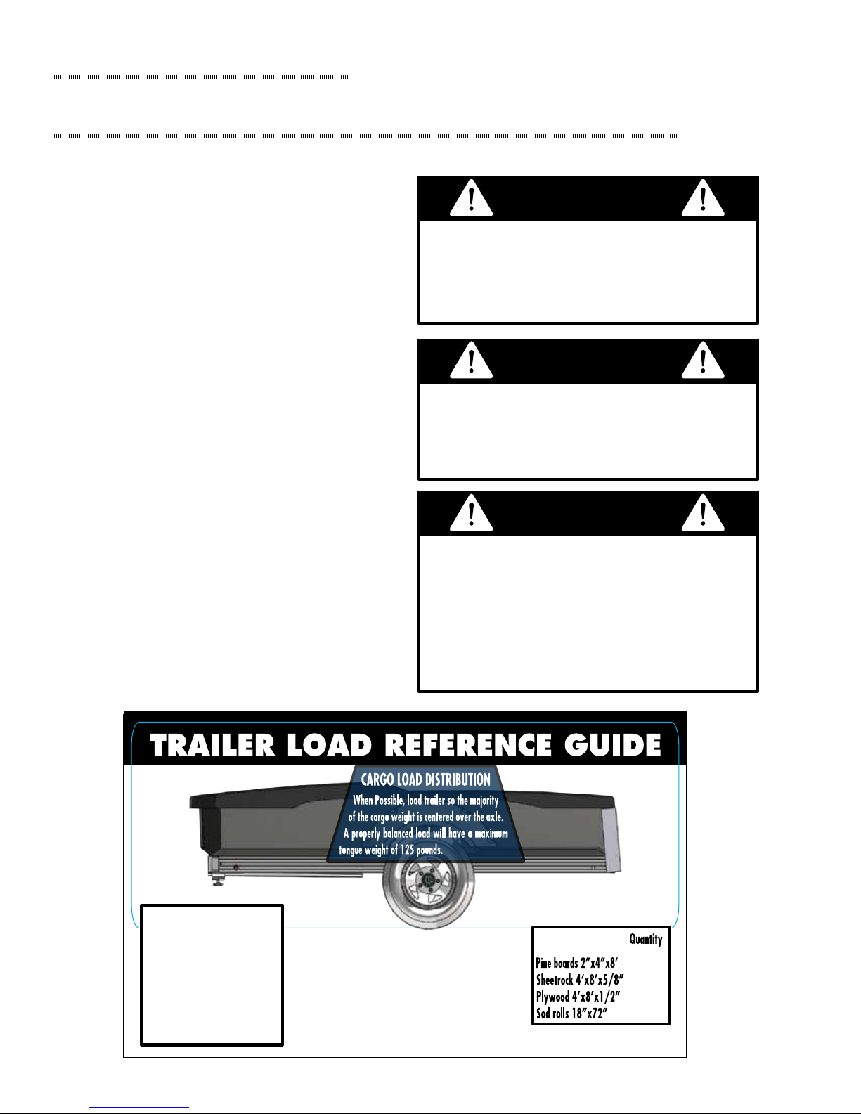
Capacity & Weight Distribution ........................................... 7
Proper Loading & Unloading................................................ 8
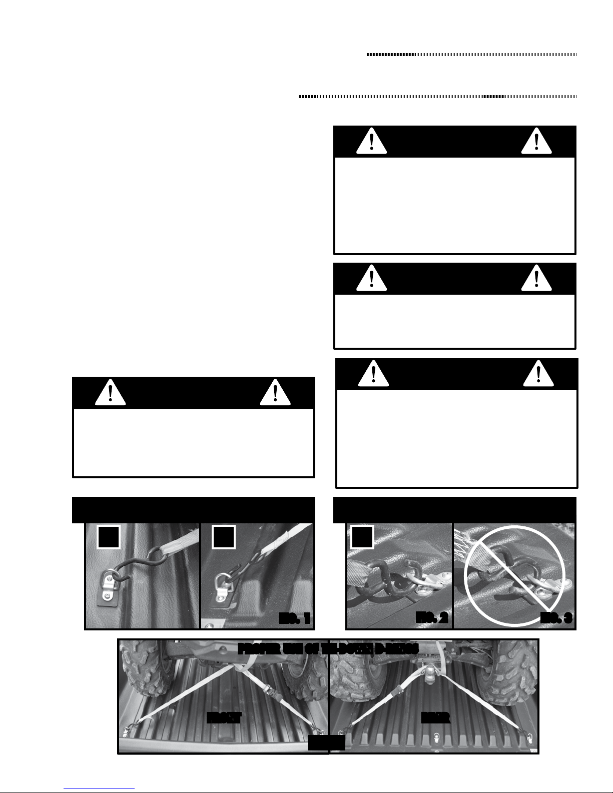
Securing the Load ................................................................. 9
Accessories ......................................................................... 10
Changing Tires .................................................................... 11
Inspections & Maintenance................................................. 11
Maintaining Hub Lubrication ............................................ 12
Installing Wheel Hub .......................................................... 13
Questions and Answers....................................................... 14
Warranty.............................................................................. 15
Warranty Registration ......................................................... 16
Contents
All material copyright © 2014 FLOE International, Inc. Unauthorized reproduction is strictly prohibited.
Serious injury, potential death or
mechanical failure could result from
neglecting to take appropriate action.
IMPORTANT SAFETY INFORMATION
WARNING
Your safety and the safety of others is very important. We have provided many important safety messages in this manual
and on your trailer. Always read and obey all safety messages.
If you do not understand any of these instructions, please ask your dealer or call FLOE customer service at 800-336-6337.
This is the safety alert symbol. This symbol alerts you to hazards that can cause
serious injury or potential death to you and others, plus damage to the
trailer. All safety messages will be preceded by the safety alert symbol
and the word “WARNING” or “CAUTION”.
All safety messages will identify the hazard and tell you how to reduce the chance of injury.
This manual includes the latest information at the
time it was printed. We reserve the right to make
changes in the product after that time without
notice. Keep this manual so it will be available to
whoever is using this product.

3
Important
Safety Information
SAFETY PRECAUTIONS
It is the owner’s/operator’s responsibility to check the
following items each time before towing trailer.
• Never exceed the trailer or tongues maximum load capacity
• When possible, position load so the weight is centered over
the axle
• Do not rely on the tailgate ramp to contain or stop cargo from
sliding or rolling out of the trailer. Use good judgment and
secure all cargo. Failure to do so may result in a road hazard
which could cause serious injury and/or death.
• The ideal tongue weight should be 6% of the cargo weight
but never over 125 lbs
• Reduce speed and/or cargo weight when traveling on rough
roads
• Over loading and improper use of this trailer could cause
structural damage, product failure and/or severe or fatal
injury
• Monitor load at regular intervals while traveling
• Check that load is positioned to apply equal weight to all tires
• Check that load is secured so it will not move while underway
• Check that no structural damage to trailer exists, do not use
if damaged
• Check that trailer is level with tow vehicle
• Check that trailer coupler is properly adjusted and securely
attached to the hitch ball
• Check that safety chains or cables are attached properly
• Check that all lights are operating correctly
• Check that bed locking system (tilt clamp) is properly secured
• Check that tires are inated to correct pressure and not
excessively worn
• Check that lug nuts on each wheel are tight
• Check that wheel bearings are properly tightened and greased
Reporting Safety Defects
If you believe that your trailer has a defect which could cause
a crash or could cause injury or death, you should immediately
inform the National Highway Trafc Safety Administration
(NHTSA) in addition to notifying FLOE International, Inc.
at 1-800-336-6337.
If NHTSA receives similar complaints, it may open an
investigation, and if it nds that a safety defect exists in a
group of vehicles, it may order a recall and remedy campaign.
However, NHTSA cannot become involved in individual
problems between you, your dealer, or FLOE International, Inc.
To contact NHTSA, you may either call theAuto SafetyHotline
toll-free at 1-888-327-4236 (TTY: 1-800-424-9153); go to
http://www.safercar.gov; or write to: NHTSA, US Department
of Transportation, 1200 New Jersey SE, Washington, D.C.
20590. You can also obtain other information about motor
vehicle safety from http://www.safercar.gov.
Failure to follow this manual’s instructions may result in
damage to your trailer or vehicle, and could cause severe
or fatal injury to you or others.
WARNING
If the trailer is not assembled, installed, or operated properly, mechanical failure as well as serious injury or death could result. See
to it that all users understand that this trailer requires the use of good judgement and the knowledge of its dangers and limitations.
Maximum tongue weight capacity is 125 lbs.
MAXIMUM CARGO CAPACITY FOR
EVENLY BALANCED LOADS IS 1800 LBS
Exceeding this load capacity could cause product failure
and/or injury and death.
WARNING

4
When selecting a hitch, there are four important things to
keep in mind:
• Load capacity -- Load should never exceed the load
capacity of your hitch or tow vehicle.
• Ball/hitch -- All FLOE tilt trailers use 2” couplers. Make
sure trailer is connected to a properly secured 2” ball and
hitch.
• In-set or out-set hitch -- FLOE recommends an out-set or
receiver-type hitch (See below).
• Hitch Height -- Hitch should be set so the trailer is level.
These illustrations show that a trailer’s turning radius is
signicantly reduced when towed by vehicles equipped with
an “in-set” hitch. To reduce the risk of tongue damage, we
recommend the use of an “out-set” or “receiver-type” hitch.
When turning or backing up, the vehicle operator must
exercise good judgement. The manufacturer will not be
responsible for damage from “jackkning.” Jackkning is
damage that results from the tongue or trailer coming in
contact with the tow vehicle.
WARNING
Out-set Hitch (Recommended)
Bumper
In-set Hitch (NOT Recommended)
Bumper
When connecting your trailer to the towing vehicle, it is
important that your hitch coupler is adjusted with the
correct amount of force for both smooth and safe trailer
performance. A loose coupler could disconnect and cause
product damage and/or serious injury or death.
WARNING
All FLOE models have a lever lock hitch coupler. With a lever lock coupler, the amount of locking force can be adjusted to
the diameter of the hitch-ball. A coupler that is adjusted too tight will make it difcult to push down on the lever lock and may
cause vibration from the trailer to the tow vehicle. A coupler that is too loose runs the risk of coming off the hitch-ball. When
properly adjusted you should be able to easily push down on
the lever lock but yet not have any rattle between the hitch-
ball and coupler when you apply upward force. To change
the amount of locking force against the hitch-ball:
1. Release the hitch coupler locking lever (to its straight up
position).
2. Locate the adjustment nut on the bottom of the hitch coupler.
3. Rotate the nut on the threaded shaft with a 3/4” socket.
Turn counter-clockwise to decrease tightness, or clockwise
to increase tightness.
4. Re-mount the trailer coupler on the hitch-ball.
5. Push down the hitch coupler locking lever to its original
locking position.
6. Repeat steps 1 through 5 until a snug t is obtained.
Do not attempt to hook up or use any trailer that has
structural damage. It is the operators responsibility to
inspect the trailer before each use. A trailer failure could
cause severe or fatal injury.
WARNING
Pulling a trailer that is not level could greatly affect the
trailer’s performance and create an uncomfortable and
dangerous situation while towing. It could also create
excessive or negative tongue weight which can cause
either tongue or axle damage.
WARNING

5
Failure to properly tighten tilt clamp and secure safety
cotter pin before towing trailer could cause the trailer to tilt
while in transit. A trailer tilting while in transit could cause
product failure, and/or severe or fatal injury.
WARNING
Note: If your trailer does not stay in the tilted position:
1. The tongue mounting bolt may not be tightened to optimal
tension. Torque to 60 Ft/Lbs
The FLOE tilt clamp eliminates the hassle and rattle of a
hitch pin design. To tilt, simply loosen the handle screw,
remove the safety cotter pin, and slide clamp forward. When
nished loading or unloading, slide clamp
back on, replace cotter pin, and tighten
handle screw.
1. Loosen knob on underside of tilt
clamp.
2. Remove safety cotter pin.
3. Slide clamp forward. If the trailer is
used without tailgate ramp, slide the
limiter strap bracket ahead along with
the tilt clamp. This will allow the bed to
tilt back until it touches the ground.
4. To tilt trailer push down on rear of
trailer.
5. Load trailer (see section on “Proper
Loading and Unloading”)
6. Tilt trailer back to horizontal position
by pushing down on front of trailer.
7. Slide tilt clamp back to original position,
replace safety cotter pin, and tighten
the knob enough to prevent it from
loosening during use.
Trailer in
limited tilt mode
using limiter strap
and tailgate ramp
Trailer in full tilt
dump mode
Trailer in level ramp mode -
slide clamp forward to tilt
Tilt Clamp bolt knob must be cleaned and greased
annually to prevent signicant corrosion. Failure to do so
can result in repairs not covered by the warranty.
WARNING
Tighten knob bolt. Using Q-Tip or small brush, apply anti-
seize to as many threads as possible, and generously to the
top of the nut.
Loosen knob bolt as much as possible. Last two threads are
deformed on purpose - DO NOT FORCE PAST THEM - and
apply anti-seize generously. Slide clamp back on and tighten
knob as usual.
2
1

6
- - - - - - - - - - - - IMPORTANT- - - - - - - - - - - -
For wiring and light replacement parts, see the assembly
instructions.
WIRE HARNESS CONNECTOR
• Your trailer is equipped with a plug-in receptacle on the
trailer tongue (FIG. 1) to keep the electrical connector
protected when not in use, as shown.
• To ensure trouble-free use, periodically inspect end plug for
tight, corrosion-free contact and apply electrical grease as
necessary to prevent future corrosion.
The wiring diagram below provides the information needed
for wiring the towing vehicle harness/connector. It is
important that the proper connections be made and that the
system is tested before using your trailer.
WIRING TESTER
To test the wiring
on your tow vehicle
you can purchase an
inexpensive tester
at most auto supply
stores.
White - Grounds all lights
Brown - Front & rear marker lights
& tail lights
Yellow - Left turn/brake light
Green - Right turn/brake light
Lights must be properly connected to the tow vehicle and
checked prior to each trailer use. Do not use trailer on
any public road without all lights functioning properly.
Malfunctioning lights fail to give other motorists proper
notication of your actions and location which can cause a
serious or fatal accident.
WARNING
Make sure the wiring harness for the lighting system is
long enough so that it is does not become unplugged when
turning sharp corners. Disconnected lights can cause a
serious or fatal accident.
WARNING
PROPER CONNECTION OF WIRING

7
CARGO WEIGHT DISTRIBUTION
• It is extremely important to never exceed the maximum
cargo capacity.
• Maximum cargo capacities are for evenly distributed loads
which place the majority of the cargo’s weight directly
over both wheels evenly. A good example of this would be
hauling several sheets of plywood.
• Loads should also be placed to distribute equal weight to
both tires. This will balance your load and give you the
best wear on your tires.
• Never place more than 50% of the total cargo capacity on
one side of the trailer.
290/132
Never exceed Trailers Max GAWR (Gross Axle Weight Rating) and tongue weight capacity.
Trailers cargo load capacity is reduced by the weight of additional options such as ramps, gates or cargo caps.
Specifications
Load Capacity
lbs/kgs Max. tongue wt.
lbs/kgs GAWR
lbs/kgs Tires
1800/815 125/56 2090/948 5.30 x 12” -C
GVWR
lbs/kgs
2140/969
Trailer Weight
(no accessories)
TONGUE WEIGHT CAPACITY
• It is extremely important to never exceed the maximum
tongue weight capacity. Over loading the tongue could
cause it to bend or break. A broken tongue could cause a
serious or fatal accident.
• Loads should be placed on the trailer so that proper weight
is applied to the tongue. The ideal tongue weight should be
6% of the cargo weight but never over 125 lbs. Increase or
decrease the tongue weight by moving the load forward or
backward.
• 125 pounds is generally easy to lift for most people. It is
the users responsibility to understand what 125 pounds or
less is.
Tongue jack must be properly secured in the travel position
before moving the trailer (see image below). Simplies
coupling and uncoupling to a vehicle. Swivel wheel enables
easy trailer movement by hand. Jack easily clamps to tongue
and pivots up for travel.
CORRECT
INCORRECT
CONNECTING SAFETY CHAINS
Safety chains must be hooked up every time the trailer is in
use. To connect safety chains properly be sure they cross each
other and the open end faces the trailer (see images below).

8
Failure to follow the listed steps when loading or unloading
could result in damage to your trailer, tow vehicle, the load
you are hauling, and/or cause possible severe or fatal
injury to yourself and others.
WARNING
Never exceed the cargo load rating of your trailer. When
the trailer is loaded with dense or wet materials the load
can easily exceed the rated cargo capacity. Do not allow the
volume of the trailer to determine the load of your trailer.
Always verify the weight of the cargo you are hauling.
Failure to do so can cause severe damage and/or failure to
the hauling vehicle, the trailer and nearby vehicles.
WARNING
1. Prior to using the trailer loaded or unloaded it is imperative
that no structural damage exists. Do a visual check to
ensure that none of the structural components are bent or
cracked.
• If damage does exist do not use the railer until it has been
repaired by an authorized repair service.
• Under no circumstances should an attempt be made to
straighten a bent structural component.
2. Never load or unload your trailer unless it is properly
connected to your tow vehicle.
3. It is imperative that your tow vehicle and trailer are parked
on level, even ground. Loading while parked on an incline
or uneven ground could cause your trailer bumper to be at
an improper angle.
4. Ensure the trailer is fully tilted and that it will stay in the
tilted position until you have driven on to it.
5. Never load moving items such as ATVs and lawn mowers
at speeds greater than 5 mph.
6. Never allow the load to cause the trailer to tilt down quickly
and with a lot of force. This could cause structural damage
to the tongue, tongue receiver and cross members.
7. After loading, make sure the tilt clamp is secure and will
not work itself loose while being towed. Make sure the
safety pin is attached.
8. Always test your footing before walking on the trailer’s
deck. It may get very slippery in cold, wet and snowy
weather.
Wood Mulch = 1 1/4 yard
Pine Lumber = 10” deep
Shell Corn = 30 Bushels
Firewood = 1 1/8 Face Cord (4’x8’x16”)
Peat = 1 1/8 yards
Black Dirt = 3/4 yard
Gravel = 1/2 yard
Sand = 1/2 yard
164
23
33
31
This information should only be used as
a reference to assist in determining
how much you can haul.
Weights are based on
normal moisture content.
When traveling on rough roads, reduce cargo weight and
speed to avoid causing structural damage to the trailer.
Failure to do so could cause product failure and/or
injury and death.
WARNING

9
Securing The Load
Do not ever strap the load to or over the side of the trailer
bed. Doing so may lead to a dangerously unsecured load
and may cause damage not covered under your warranty.
WARNING
TIE DOWN INSTRUCTIONS
1. Use any of the eight tie down D-rings in the trailer bed as
needed to safely secure your load.
• The maximum capacity of each D-ring is 500 lbs of cargo
weight. For instance: an ATV weighing 800 lbs should be
secured to four tie down loops as shown in (FIG. 4).
2. Cargo must be secured so that tie down restraints can not
become loose while traveling.
• If the load were to shift forward or backward it could
cause excessive tongue weight or negative tongue weight.
Either situation could be dangerous.
3. When securing hooks through the SIDE of the tie down
D-rings, either direction is appropriate -- see (FIG. 1).
4. When securing hooks through the TOP of the D-rings,
make sure the hook faces up -- see (FIG. 2). NEVER use
hooks in the position shown in (FIG. 3) as this provides a
greater chance of failure.
Ensure that the load is adequately secured. Load may
become loose during travel. Check your load while
traveling. Unsecured loads can cause product damage,
road hazards and/or cause severe injuries and death.
WARNING When securing cargo, consider how it will behave if
extreme acceleration, deceleration (fast braking),
swerving, or poor road conditions occur. A load that
shifts forward or backward may cause an unsafe
situation which could result in product damage,
severe injuries or even death.
WARNING
SECURING THROUGH SIDE OF D-RING
✔✔✔
SECURING THROUGH TOP OF D-RING
PROPER USE OF TIE-DOWN D-RINGS
FRONT REAR
FIG 4
Maximum tongue weight capacity is 125 lbs.
MAXIMUM CARGO CAPACITY FOR
EVENLY BALANCED LOADS
1800 lbs Cargo Max XRT 8-57
Exceeding these load capacities could cause product failure
and/or injury and death.
WARNING

10
Procedure for
When using the tailgate ramp, the trailer can either be left in regular (upright) position, or partially tilted using the limiter strap.
This creates the perfect angle for low clearance items.
Tailgate ramp removes in
seconds with no tools.
Simply tilt back and remove.
To lower tailgate ramp,
simply squeeze the spring-
loaded center latch.
Tailgate latch pins must be regularly inspected, cleaned and lubricated with a spray silicone-based lubricant to prevent binding.
Failure to do so can result in repairs not covered by the warranty.

11
Do not rely on the tailgate ramp to contain or
stop cargo from sliding or rolling out of the trailer.
Use good judgment and secure all cargo.
Failure to do so may result in a road hazard
which could cause serious injury and/or death.
WARNING
Check web site for additional accessories and options.
www.oeintl.com
MAG WHEEL
Dress up your Cargo Max
with these stylish mag
wheels. Always look
great and will never
need painting.
Procedure for
Changing Tires
CHANGING TIRES
1. Start all lug nuts by hand to prevent cross-threading and to
ensure proper nut-to-rim seal.
2. Tighten bolts in the sequence detailed below in stages, rst
tighten to 25 ft./lbs. then 60 ft/lbs. and nally 80 ft./lbs.
3. Inate tires to proper PSI as noted on the sidewall of the
tire.
4
5
1
Improper tire pressure can create
severe dangers. Be sure your tires are
always properly inated.
The proper pressure for your tires can be
found on the side wall of tire.
WARNING
Change worn tires. A tire failure could
result in an uncontrollable road hazard.
WARNING

12
It is very important to read and follow these maintenance procedures to help avoid trailer failure. Any trailer failure resulting
from improper maintenance may void your warranty.
Procedure for
COMPONENT AVOID
Structure/Frame a) Do a visual check to ensure that none of the structural
components are bent or cracked before towing. If damage
does exist do not use the railer until it has been repaired by
an authorized repair service.
a) Loading the trailer in an unbalanced
fashion (heavy on one side).
b) Exceeding capacities of trailer and
tongue.
Wheel Hubs a) Adjust wheel bearings within the rst 100 miles and every
2,000 miles, or annually thereafter, whichever comes rst.
(Inspect bearings, seals, and races - replace if worn.) To
check for wear, jack up the trailer and pull on each wheel to
see if there is any in and out play or “slop.”
a) Getting sand in hubs or bearings.
b) Neglecting to grease hubs.
Axle a) Inspect trailing arms to make sure they are straight. a) Leaving loaded for long periods
Tires a) Keep tires properly inated.
b) Inspect periodically. (Replace when necessary)
a) Leaving loaded for long periods
b) Driving with worn tires.
Aluminum
Surfaces
a) Rinse periodically with water, particularly if driven on
“salted” roadways.
b) Remove grease, oil and dirt by scrubbing with soft bristle
brush and mild detergent. Rinse with clean water.
a) Harsh, abrasive cleaners.
b) Bolting or hard-mounting dissimilar
metals to aluminum surfaces.
Molded Bed a) Visually check for cracks. a) Storage in direct sunlight.
Electrical
System
a) Check that all lights are functioning properly before towing.
b) Periodically check for build-up of oxidation or corrosion
and clean when necessary. Use electrical grease in all wire
and bulb connections to help prevent corrosion.
a) Leaving electrical connections
exposed to elements and potential
abrasions.
Tailgate
Latch Pins
a) Remove debris from pins and lubricate with a silicone-
based spray.
a) Neglecting to lubricate pins for long
periods.
Tilt Clamp Knob a) Remove debris and apply grease to knob threads. a) Neglecting to grease threads for long
periods.

13
Procedure for
WHEEL HUB LUBRICATION
Your hub/spindle is equipped with a lubrication system. The
bearings can be periodically lubricated without removing the
hubs from the axle. The advantage to this system is that new
grease saturates the inner bearing and outer bearing while
pushing out the old grease, unlike systems that just push new
grease on top of old grease.
1. Remove the rubber plug from the grease (hub) cap.
2. Use a standard grease gun on the grease tting located at
the end of the spindle, or behind the hub, making sure the
grease gun nozzle is engaged on the tting tightly.
3. Pump grease into the tting, while slowly turning the
wheel. Grease will ow out of the hub around the spindle.
4. When the grease appears to be the new clean grease,
remove the grease gun and wipe off any excess grease.
5. Replace the rubber plug in the cap.
- - - - - - - - - - - - - - IMPORTANT - - - - - - - - - - - - - -
A complete inspection and greasing of wheel hubs is required
annually or every 2,000 miles, whichever comes rst.
Procedure for
Removing the hub for inspection or maintenance should be
done in a safe location away from moving vehicles.
1. Safely elevate and block trailer so that it will not move.
2. Remove the tire/wheel assembly.
3. Remove the grease cap from the hub by prying around the
edge of the cap.
4. Bend the locking tang washer to the “free” position.
5. Remove the spindle nut in a counterclockwise direction and
remove the spindle washer.
6. Remove the hub from the spindle. Be careful not to allow
bearings to fall out of the hub.
7. Clean bearing and cup surfaces, repack with lithium marine
grade grease.
8. Place hub on spindle in reverse order as listed above. Rotate
the hub while tightening the spindle nut to approximately
50 ft lbs. This translates into full hand pressure with a 12”
long set of pliers or 12” long wrench.
9. Loosen the spindle nut. Do not rotate hub.
10. Finger tighten the spindle nut until snug, backing out only
to line up the locking tang washer.
11. Bend the locking tang tab in place.
12. Replace grease/hub cap.
13. Test hub with wheel mounted for excessive play or
tightness, readjust if required.

14
SUPER LUBE
LIMITED WARRANTY
Limited Warranty TIE DOWN ENGINEERING Inc. ("TIE DOWN") warrants its products to be free from defects in material and workmanship for one year
from date of delivery when properly maintained by the purchaser. One year for parts and labor.
This warranty does not apply to damage or loss caused by any or all of the following circumstances or conditions:
• Damage caused during installation.
• Parts, accessories, materials or components used with or replacing any TIE DOWN braking system not obtained from or approved in
writing by TIE DOWN.
• Misapplication, misuse and failure to follow the directions or observe cautions and warnings on installation,operation, application,
inspection or maintenance specified in any TIE DOWN quotation, acknowledgement, sales literature, specification sheet or installation
instruction and service manual ("applicable literature").
• Use of product in any other application other than those described in TIE DOWN’s product information materials.
If any TIE DOWN products are found upon TIE DOWN's examination to have been defective when supplied, TIE DOWN will either: credit the purchaser's
account for the purchase price of the TIE DOWN product; replace the TIE DOWN product; or repair the product. TIE DOWN has sole discretion in choosing
which option to provide. For this LIMITED WARRANTY to apply, TIE DOWN must receive notice of the alleged defect within 30 days of either the discovery
of the alleged defect or the expiration of the warranty period, whichever is earlier. Any claim not made within this period shall conclusively be deemed
waived.
If requested by TIE DOWN, purchaser shall return the alleged defective product to TIE DOWN for examination at purchasers expense. TIE DOWN will not
pay for expenses incurred in returning a product to TIE DOWN without TIE DOWN's prior written authority. TIE DOWN shall not be liable for any other
expenses purchaser incurs to remedy any defect. Purchasers waive subrogation on all claims under any insurance.
Limitation of Liability: It is expressly agreed that the liability of TIE DOWN is limited and TIE DOWN does not function as an insurer. THE REMEDIES SET
FORTH IN THIS WARRANTY SHALL CONSTITUTE THE EXCLUSIVE REMEDIES AVAILABLE TO THE PURCHASER OR USER AND ARE IN LIEU OF ALL OTHER
REMEDIES, EXPRESS OR IMPLIED. THE LIABILITY OF TIE DOWN, WHETHER IN CONTRACT, IN TORT, UNDER ANY WARRANTY OR OTHERWISE, SHALL NOT
EXCEED THE PURCHASE PRICE OF THE PARTICULAR PRODUCT MANUFACTURED, SOLD OR SUPPLIED BY TIE DOWN.
To Obtain Technical Assistance: To enable TIE DOWN to respond to a request for assistance or evaluation of customer or user operating difficulty, please
provide at a minimum the following information by calling 404-344-0000:
• Model number, serial number and all other data on the specific component which appears to be involved in the difficulty.
• The date and from whom you purchased your TIE DOWN product.
• State your difficulty, being sure to mention at least the following: Application, Nature of load involved, and Weight of the load.
Field Service If field service at the request of the purchaser is rendered and the difficulty is found not to be with TIE DOWN's product, the purchaser
shall pay the time and expense (at the prevailing rate at the time of service) of seller's field representative(s). Charges for service, labor and other
expenses that have been incurred by the purchaser, its customer or agent without prior written authorization of TIE DOWN will not be accepted.
TIE DOWN EXTENDS NO WARRANTY, EXPRESS OR IMPLIED, ON PRODUCTS NOT MANUFACTURED BY TIE DOWN OR TO TIE DOWN'S DESIGN SPECIFICATION,
INCLUDING BUT NOT LIMITED TO SUCH ITEMS AS NON-TIE DOWN TIRES, BRAKES, ACTUATORS, BEARINGS, HOSE AND TUBING. PURCHASER'S RECOURSE
SHALL BE LIMITED TO ANY WARRANTY OF THE RESPECTIVE MANUFACTURERS.
THIS WARRANTY EXCLUDES ALL IMPLIED WARRANTIES OF MERCHANTABILITY OR FITNESS FOR A PARTICULAR PURPOSE OR ANY PURPOSE.
THIS WARRANTY DOES NOT COVER NOR EXTEND TO INCIDENTAL OR CONSEQUENTIAL DAMAGE. Some states do not allow the exclusion or limitation of
incidental or consequential damages, so the above limitation or exclusion may not apply to you. This warranty gives you specific legal rights, and you may
also have other rights which vary from state to state.
No representative has authority to make any representation, promise or agreement except as stated in this Limited Warranty. TIE DOWN reserves the right
to make design and other changes upon its products without any obligation to install the same on any previously sold or delivered products.
DUE TO THE WIDE VARIATION IN USES TO WHICH TIE DOWN PRODUCTS (WHEELS, HUBS, BRAKES, ETC.) ARE SUBJECTED BY USERS, WE ARE UNABLE TO
SPECIFY CARRYING CAPACITIES OR SPEEDS FOR A PARTICULAR APPLICATION. THEREFORE, THE MANUFACTURER MUST TEST HIS EQUIPMENT UNDER THE
MOST SEVERE CONDITIONS TO DETERMINE THAT TIE DOWN PRODUCTS ARE SUITABLE.
THERE ARE NO WARRANTIES WHICH EXTEND BEYOND THOSE DESCRIBED ABOVE. EFFECTIVE JANUARY 2003 THIS WARRANTY
SUPERSEDES ALL PRIOR WARRANTIES, WRITTEN OR IMPLIED.
082114,C1288
TIE DOWN ENGINEERING • 255 Villanova Drive SW • Atlanta, GA 30336
www.tiedown.com (404) 344-0000 Fax (404) 349-0401
Part #08200

15
WHAT CAN CAUSE VIBRATION IN MY TOW
VEHICLE?
1. Over-tight hitch coupler -- See procedure for adjusting
hitch coupler earlier in this book.
2. Loose or worn wheel bearings -- See procedure for replacing
wheel hub earlier in this book.
3. Loose wheels -- See procedure for changing tires earlier in
this book.
4. New tires -- It is possible that the new tires are out of
round. Once they are inated to the proper PSI and used
for a short period of time on a loaded trailer, they should
work themselves round. New tires that are still out of round
after an ample break in period may be defective and need to
be replaced. Call the tire manufacturer or your local FLOE
dealer for replacement.
5. Unbalanced wheel hubs -- If your tires are balanced and
not out of round this may be the problem. Replace if
necessary.
WHY DOES MY TRAILER SWAY OR WHIP?
1. Trailer is not being towed level -- Refer to hitch selection
and use section of this manual.
2. Not enough tongue weight -- Refer to loading and unloading
section of this manual.
3. Overloaded trailer -- Refer to loading and unloading section
of this manual.
4. Too much tongue weight -- Refer to loading and unloading
section of this manual.
WHY ARE MY TIRES WEARING UNEVENLY?
1. Unequal side-to-side loading -- Refer to Proper Loading
and Unloading section of this manual.
2. Tires not inated to proper PSI
3. Wheel bearings are not properly tightened & oiled.
CAN I REPLACE MY TIRES WITH LARGER ONES?
1. No, The Cargo Max was designed for use with 5.30 x 12”-C
tires and these may not be substituted for a larger size. A 12”
mag wheel upgrade is available.
CONNECT OR USE MY TRAILER LIGHTS?
1. A wire is cut or bare and is shorting out -- Visually locate
and repair or replace.
2. Wrong size fuse in tow vehicle -- The trailer lighting system
draws 1/2 amp not taking into account anything else on this
circuit.
1. Corrosion on wire connections -- Check all connections
for corrosion, clean and apply electrical grease to prevent
future corrosion.
2. Improper or loose ground to tow vehicle -- This may cause
all lights to blink or cause your marker lights to blink when
you turn on your turn signals.
HUBS?
1. High-quality high-temperature lithium wheel bearing
grease. Never use grease heavier than 265 A.S.T.M.
penetration (No. 2 grade).
- - - - - - - - - - - - - - IMPORTANT- - - - - - - - - - - - - -
For additional information, please contact your Authorized
FLOE Dealer, visit our website at www.oeintl.com or call:
1-800-336-6337 to locate the dealer nearest you.

16
WARRANTY REGISTRATION
NOTE: If you are unable to register online, please photocopy and ll out the form below and place in an envelope with
proper postage or quickly register online. Please complete all information requested and address it to: FLOE International
Inc., Warranty Registration Dept., 48473 State Hwy 65, McGregor, MN 55760-9514. FLOE INTERNATIONAL, INC. is not
responsible for lost, stolen or misplaced warranty registrations.
NAME: _________________________________________________________________ PHONE: ______ / _______________
ADDRESS: ____________________________________________CITY: __________________ STATE: __________ ZIP: ________
DATE PURCHASED: ________/ ________/ ________ PURCHASED FROM: _______________________________________
E-mail: _____________________________________________
Yes please No you cannot contact me via e-mail with great offers and special promotions from FLOE International and it’s quality authorized dealers.
PRODUCT PURCHASED Please check all that apply
FLOE CARGO MAX XRT 8-57........ VIN#:_________________________________________
Optional Tongue Jack Optional Tailgate Ramp Optional Mag Wheels Optional Spare Tire
TELL US ABOUT YOURSELF
How did you hear about FLOE: _______________________________________________________________________________
Family Income: 25,000 - 50,000 50,000 - 75,000 75,000 - 100,000 100,000 - 150,000 150,000 - 250,000 over 250,000
Your Occupation:
Professional/Technical Upper Management/Executive Middle Management Sales/Marketing Clerical/Service Worker Tradesman/Machine Operator/ Laborer
Spouses Occupation:
Professional/Technical Upper Management/Executive Middle Management Sales/Marketing Clerical/Service Worker Tradesman/Machine Operator/ Laborer
Age Range: 18 - 29 30 - 45 46 - 60 over 60 Education: High School 2 year college 4 year college Graduate school
What most inuenced you to buy a FLOE product: (select one) Advertisement Quality Warranty Price Style/Appearance Features/Benets
P/N 500-95030-00 9/15
CARGO MAX XRT 8-57
All material copyright © 2015 FLOE International, Inc. Unauthorized reproduction is strictly prohibited.
FLOE International warrants, to the original purchaser Cargo Max trailers to be free from original defects in materials and workmanship under the conditions
and loads for which designed and from date of purchase as follows:
ALUMINUM TRAILER STRUCTURES, LIGHTING SYSTEM AND FORMED CARGO MAX BED
FLOE INTERNATIONAL will repair or replace, at its option, any portion of the aluminum structure, formed trailer bed and lighting system (excluding L.E.D. bulbs
and lenses,) which fails as a result of a defect in material or workmanship during the rst year after purchase.
AXLE AND HUB
Axle, hubs, drums, brakes, bearings and seals are covered for a period of one (1) year from the date of purchase when installed, used and maintained properly
by the purchaser. Warranty service is provided and performed by the manufacturer “Tie Down Engineering”. Tie Down can be reached for warranty service
during normal business hours at 404-344-0000.
TIRES
Warranty is provided by the tire manufacturer Green Ball Corp. Green Ball can be reached for warranty service during normal business hours at 1-800-946-9412.
This warranty covers only the cost of replacement of materials due to defects in materials or workmanship and represents the only warranty authorized by us. In order to receive
performance under this warranty, all warranty repairs must be authorized in advance by FLOE International. FLOE International will not be responsible for any costs incurred for
unauthorized repairs! Unauthorized repairs may void the warranty on items repaired! This warranty does not cover any damages due to overloading of trailer, damage resulting
from road hazards, damage caused by wear rods or traction products, jackkning, misuse, or negligence. This warranty covers personal use and does not apply to commercial or
rental uses. The manufacturer is not responsible for damage where repairs have been made or attempted by others. Items purchased by FLOE INTERNATIONAL are warranted by
the original manufacturer and warranty is extended to the original purchaser. FLOE INTERNATIONAL reserves the right to inspect and perform rework at its main facility (F.O.B.)
McGregor, Minnesota. Freight is the responsibility of the consumer. Specications may change without notice or obligation. To receive performance under this warranty, contact FLOE
International, Inc. at 218-426-3563.
THERE ARE NO OTHER EXPRESSED WARRANTIES OR ANY IMPLIED WARRANTIES.
Our obligations under this warranty are limited to repair or replacement at our discretion,
AND WE SHALL NOT BE LIABLE FOR INCIDENTAL OR CONSEQUENTIAL DAMAGES OF ANY KIND.
This warranty gives you specic legal rights and you may have other rights which may vary from state to state.
Table of contents
Other Floe Utility Vehicle manuals