Flonidan UNIFLO G4S Series User manual

G4SZV-1 V1.5 Page 1
USER MANUAL
Copyright © 2014 Flonidan a/s. All rights reserved. This document
contains proprietary information to the Flonidan A/s Company.
Furnishing this document does not convey any reproduction or
manufacturing rights. It may not be used, published, or disclosed to
others without the express authorization of Flonidan A/s.
Title: Diapgragm GAS METER SMETS 2 UK USER MANUAL
Originator: Dave Kerr
Project Code Name: G4SZV-1
Current Revision: Version 1.5
Last Requirement: NONE added
Department: Product Management
Revision History
Revision
Changed by
Description
Date
Version 1.1
Dave Kerr
Created
1 Aug 2016
Version 1.2
DK & MBP
Editorial changes only
28 Oct 2016
Version 1.3
MEPH
Regulatory changes
09 Oct 2017
Version 1.4
Dave Kerr
Remove SMETS1 remnants & update for SMETS2
12 Dec 2017
Version 1.5
DK & MEPH
Editorial only
2 Aug 2018

G4SZV-1 V1.5 Page 2
G4SZV-1 PICTURE

G4SZV-1 V1.5 Page 3
TABLE OF CONTENTS
.................................................................................................................................2
G4SZV-1 PICTURE.................................................................................................2
TABLE OF CONTENTS..........................................................................................3
1. Before You Start ................................................................................................5
2. Product Description..........................................................................................5
2.1 Dimensions........................................................................................................................7
2.2 Gas Flow Rates .................................................................................................................7
2.3 Pipe Connection.................................................................................................................7
2.4 Optical Port........................................................................................................................8
2.5 Battery ...............................................................................................................................8
2.6 Operating Range................................................................................................................8
2.7 Model Variants & Identification ..........................................................................................8
2.8 Liquid Crystal Display ......................................................................................................10
Display test.........................................................................................................................11
2.9 Menu Structure ................................................................................................................12
2.9.1 Input methods using Push Buttons............................................................................18
3. Billing and Tariffs............................................................................................19
3.1 Tariffs...............................................................................................................................19
3.2 Block Tariffs.....................................................................................................................19
4. Mechanical Operation.....................................................................................20
4.1 Diaphragm Valve Mechanism..........................................................................................20
4.2 Encoder Index..................................................................................................................20
4.3 Gas Flow Measurement...................................................................................................22
4.4 Error Curve Correction.....................................................................................................22
4.5 Temperature Correction...................................................................................................22
5. Meter Security..................................................................................................23
5.1 Index Cover .....................................................................................................................23
5.2 Metrology Compartment Tamper Detection.....................................................................23
5.3 Magnetic Tamper Detection.............................................................................................23
5.4 Encryption........................................................................................................................23
6. Memory.............................................................................................................24
7. Supply Valve (Electro Valve)..........................................................................24
Working Principle...................................................................................................................24
7.1 Supply Disconnect (close valve)......................................................................................24
7.1.1 Supply Disconnection from HES ...............................................................................24
7.1.2 Supply Disconnection during Prepay operation mode...............................................24
7.1.3 Supply disconnection due to an Alarm. .....................................................................24
7.1.4 Supply Re-connect (open valve) ...............................................................................24
7.1.5 Supply re-connection from HES................................................................................25
7.1.6 Supply re-connection during Prepay operation mode................................................25
7.1.7 Supply re-connection due to an Alarm being cleared................................................25
7.2 Supply (valve) status........................................................................................................25
7.3 Safe Opening Process.....................................................................................................25

G4SZV-1 V1.5 Page 4
8. Firmware...........................................................................................................26
8.1 Firmware Variants............................................................................................................26
8.2 Firmware Upgrade...........................................................................................................27
9. Change of Supplier (CoS)...............................................................................27
10. Change of Tenancy (CoT).............................................................................27
11. Communication Features and Functionality..............................................28
12. Clock...............................................................................................................28
13. SMETS2 ALERTS...........................................................................................28
14. FLONIDAN Alarms data logging..................................................................29
14.1 Data logging...................................................................................................................29
14.2 Alarm Push Filter and Push Register.............................................................................30
14.3 Battery Low Alarm..........................................................................................................30
15. Maintenance...................................................................................................31
15.1 Battery life Calculation...................................................................................................31
15.2 Battery exchange...........................................................................................................31
15.3 Service...........................................................................................................................32
15.4 Repair............................................................................................................................32
15.5 Returning a Meter..........................................................................................................32
15.6 Meter Disposal...............................................................................................................32
15.7 Cleaning.........................................................................................................................32
15.8 Storage..........................................................................................................................33
16. Technical Specifications at a glance...........................................................33
17. Abbreviations.................................................................................................34

G4SZV-1 V1.5 Page 5
1. Before You Start
The G4S series meter is a high accuracy measuring instrument that must be handled with
care. The meter should always be kept in vertical position, in service and during
transportation.
The device should be fitted only by competent engineers, qualified to the relevant national
legal requirements and following all national and local regulations such as BS 6400
2. Product Description
G4S series meter is a smart diaphragm gas meter, SMETS compliant, with an electronic
index. The meter includes ZigBee radio and an integrated electrically operated valve. The
meter displays the accumulated consumption in m3 or currency, selectable by the menu
system, on an integral LCD.
This G4 (U6) capacity diaphragm gas meter i.e. Qmax = max flow rate = 6 m3/h, is
intended for domestic and small industrial use.
The measuring chamber is a “sliding D” diaphragm type. An optical interface provides the
coupling between the measurement chamber inside the casing and the electronic index.
The optical interface uses a Gray scale methodology providing reliability, very precise
accuracy, and reverse flow detection.
The dot matrix display allows for the two lines of data required by SMETS1. In addition,
there’s space for other icons used to assist the end user or installations engineer.
The meter has a HAN interface solution designed for the ZigBee RF interface 2.4MHz and
the SEP 1.x requirements.
A user-friendly configuration software allows all functions to be accessed by the optical
communications connection located on the front face of the index.
Reading and writing possibilities can be controlled by a customised setup file.
The meter can be configured (by the HES) to run in two modes
1 Credit mode: the user will accumulate charges that will be shown on the display.
This will be transferred to the HES and an automatic bill can be generated, on a
monthly or Quarterly period.
2 Prepay mode: the user will purchase “upfront” an amount of prepaid credit that
they will then be able to use. This prepay credit is purchased “online” or in local shops and
is known as a UTRN code (Universal Transaction Reference Number) after the total
prepaid amount is depleted the gas meter will close the gas supply. Certain measures are
implemented to prevent closure at certain times (i.e. when the shops are closed and it is
not possible to purchase a UTRN, these are known as Friendly credit periods and are
decided by the utility alone), in addition special emergency credit facilities may be offered
in certain circumstances.

G4SZV-1 V1.5 Page 6
The meter has an internal valve, electronically controlled, to allow the gas supply to be
disconnected and reconnected as required. The gas supply cannot be reconnected
without the presence of someone at the meter. When the command to open the valve is
received by the meter, a button press is then required at the meter. If the meter detects
passing gas above a predefined rate, indicating a potential gas leak, it will close the valve.
Checks should then be made to ensure gas appliances are turned off before a second
attempt to open the valve is made.
Physical Component Overview
Electronic index
Installation
seals
(side locks)
Optical port
Display
Verification
seal
Press buttons
Battery behind
cover and label
Meter Serial Number
(MSN)
GUID (MAC NUMBER)

G4SZV-1 V1.5 Page 7
2.1 Dimensions
2.2 Gas Flow Rates
1) Air, at Qmax.
2) Temperature compensation optional
2.3 Pipe Connection
Pipe connection size : 1” BSP, sealing gasket required
Inlet pipe connection : Left side
Outlet pipe connection : Right side
Direction of flow : Left to right
H
W
D
d
c/c
T
M
Mm
mm
mm
mm
mm
mm
kg
G4
262
235
167
73
152
BS 1”
2.5
Vcyc.
Qmax
Qmin
Pmax
ΔP1)
TC2)
dm3
m3/h
m3/h
bar
mbar
G4
1.2
6
0.04
0.5
1.6
X

G4SZV-1 V1.5 Page 8
2.4 Optical Port
NOTE, due to CPA security concerns, this port is turned off at manufacture
and cannot be used in the field.
Optical interface (IEC 62056-21) for specialist maintenance.
2.5 Battery
Type : C cell, Lithium, 3.6V
Lifetime : > 15 years, with normal use
The index and valve are powered by the battery. However, to enable high peak
current supply, a super-capacitor is charged over a long time and discharged
over a short time to operate the motor of the valve.
Note: Only approved battery cells may be used in this product to maintain
ATEX intrinsic safety certification. Please contact the Flonidan for the correct
replacement battery.
2.6 Operating Range
Environmental class
Climate : Outdoor, sheltered, condensing.
Mechanical and Electromagnetic class : M1, E2
ATEX : II 2/2 G Ex ia/ib IIB T3
The meter is designed for use in a hazardous area according to EU Directive
1994/9/2007.
Refer to marking on meter.
Temperature range:
Tamb.: -25...+55°C
Tgas.: -25...+55°C
Gas types:
The gas meter is suitable for gas families 1, 2 and 3 according to EN 437:2003
Max. pressure:
200 mbar gauge
Metering Accuracy
MID Class 1.5
2.7 Model Variants & Identification

G4SZV-1 V1.5 Page 9
The Model name as shown on the index label takes the form:
G4SZV -1
-X where X is version (eg 1 = SMETS2)
V: Integrated valve
Z: ZigBee
S: Smart Meter
G4: Meter G-size
Future variants could include different flow range and different communication
interface type.
The type and version of the PCB located inside the index may be read by an
optical interface, through the front cover. Along with the hardware and firmware
type and versions, you can read the entire configuration of the index. (see section
9.1)
You will also find the unique Meter Serial Number (MSN) of the meter, in the form
“G4F………..” below the display.
There is also the Flonidan internal serial number in the form “S/N 115xxxxxxxx”,
there is full traceability of the internal components of the meter from the either of
these numbers.
G4SZV-1 V1.5 Page 10
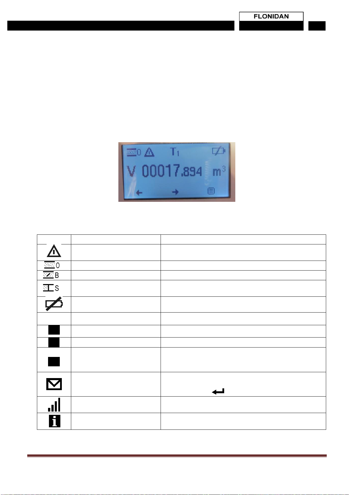
2.8 Liquid Crystal Display
Display is readable at angles ± 45° horizontally as well as vertically at temperatures
within the operating range.
Volume read out for the UK is set to the form “xxxxx.yyy” it is not configurable and will
always display leading zeros, as per SECAS rules.
Example: (note leading Zeros may be hidden)
Symbols shown at the top of the display when either the volume or the balance screen is
displayed:
Meaning
Required action
Alarm
Go to the menu, select Alarms + Actual alarms, and you will
see the alarm
Valve open
No action
Valve busy (opening or closing)
Observe if the gas is disabled
Valve shut
When valve is closed, gas is disabled. Contact gas utility, and
press the button when the meter requires it.
Low Battery
Battery must be exchanged within 30 days.
EC
Emergency Credit Available
Use Menu to accept Emergency Credit to avoid disconnection
EC
Emergency Credit in USE
Emergency Credit is being used
LC
Low Credit
Top up, to avoid incurring Debt or being cut off
ND
Non Disconnect
The meter is OUT OF CREDIT, and would have disconnected
but will remain on supply, because of the Non Disconnect
period
Message waiting (from Utility)
Go to menu + Message, and scroll through the incoming
messages.
Acknowledge with
Paired to Communication Hub
All ok. If the symbol is not present, there is no connection to
the HAN
Information waiting (from gas
meter)
Go to menu + Information, and scroll through the incoming
Information. Acknowledge with by pressing button below [i]

G4SZV-1 V1.5 Page 11
Menu driven display, to access all functions on the meter
Navigation symbols are shown at the bottom of the display to indicate the function
of each of the three pushbuttons located directly below:
Symbol
Meaning
Symbol
Meaning
Scroll down
Scroll up
Scroll left
Scroll right
Select, Acknowledge
Main menu
Display test
A display test can be activated through the menu on the User Interface. Chequered
patterns are displayed that covers the entire display to check for failing pixels.
Sleep mode
The display and backlight are turned off after a period of time of inactivity to
conserve battery power. The periods are configurable, with a default setting of both
at 15 seconds. If this display has used its maximum amount of display time
available (configuration setting) the display will not switch on for a period of time
allowing the display time credit to build up again. This function is implemented to
prevent customers draining the battery.

G4SZV-1 V1.5 Page 12
2.9 Menu Structure
The “normal” and default display is the Vc i.e. Total Volume in m3
The display can be switched between Vc (m3) & Meter balance £ using the left hand
button which is marked “A” shown on the display as “BAL” or “VOL”
While in the “normal” display the meter can be switched into the Menu structure below using the Key
Note if no buttons are pressed for approx. 10 seconds, the meter will exit the menu and return to the Normal
display.
Level 1
Level 2
Level 3
Display read out
Comments
Use Key
to enter Menu
structure below
In the order
shown from top
to bottom
Meter Balance
This returns the display to the
normal volume display
INSTALL
NOTE This option is ONLY
shown if the meter has not
been paired and is for the use
of installers only!
WAKE UP
This allows the end user or
engineer to force an extra
wake up (only once per 30
mins)
TIME OF USE
Only displayed
if Time of use
is being used.
Tariff m3
Total volume
metered
T1
T2
T3
T4
m3in the form xxxxxxx.yyy
Switch to next level 2 with ←
→(arrow keys)
Tariff kWh
Total kWh
metered
T1
T2
T3
T4
kWh in the form “xxxxxxx.yyy
switch to next level 2 with ←
→(arrow keys)
Tariff £
Total money
metered
T1
T2
T3
T4
£ in the form “x.yy”
Switch to next level 2 with ←
→(arrow keys)
Tariff £/kWh
Price of Tariff
per kWh
T1
T2
T3
T4
£/kWh in the form “x.yy
Switch to next level 2 with ←
→(arrow keys)
BLOCK
Only displayed
if Block Pricing
is being used.
Block m3
Total volume
metered
B1
B2
B3
B4
m3in the form xxxxxxx.yyy
Switch to next level 2 with ←
→(arrow keys)

G4SZV-1 V1.5 Page 13
Block kWh
Total kWh
metered
B1
B2
B3
B4
kWh in the form “xxxxxxx.yyy
Switch to next level 2 with ←
→(arrow keys)
Block £/€
Total money
metered
B1
B2
B3
B4
£ in the form “x.yy”
Switch to next level 2 with ←
→(arrow keys
Block prices
Price for block
per kWh
B1
B2
B3
B4
£/kWh in the form “x.yy
Switch to next level 2 with ←
→(arrow keys)
Block
Thresholds
B1
B2
B3
B4
Block Thresholds in the form
“> xxxx kWh (full kWh only and
leading zeros are blanked)
Switch to next level 2 with ←
→(arrow keys)
Block USED
DURATION USE
xxxxxxx.yyy kWh
DURATION :
Full kWh that the block tariffs
have been used in the month
& the Duration in time that this
has taken (blank if no volume
used yet)
PREPAYMENT
Only displayed
if Prepayment
mode is active.
TOPUP LOGS
TOPUP LOG 1-5
Date Amount, Ref Code
For each of the last 5 top ups
the display will show The Date,
amount, Ref and Code
NEW
PAYMENT
Enter UTRN
This will allow a UTRN to be
inputted (see section 2.9.1)
DEBT
DEBT 1-2
Time based debts
Label
Amount
Method: Time
Frequency
Rec Amount
DEBT 3
Percentage based debt
Label
Amount
Method: Percentage
Rec Perc
EMERG.
CREDIT
EMERGENCY CREDIT
STATUS
Not Available/Available/in
use/Exhausted
Limit £x
This is the limit set by the
Head End system
Remaining £x
This is the emergency credit
remaining
G4SZV-1 V1.5 Page 14
STATUS
PAYMENT
MODE
Active Credit Mode /
Prepayment Mode
Shows either Credit or
Prepayment mode as active
Emergency credit
Shown in prepay mode only
CURRENT
STATUS
Switch between the 3 screens
using ← →
CURRENT
STATUS
Tariff
Shows the current tariff being
applied
Stand. Chrg
Shows the current standing
charge £/day (x.yy)
Price
Shows the current price being
applied £/kWh (x.yy)
Valve
Shows the current valve
status (open/close/busy)
ACTUAL
VALUES
Switch between the 3 screens
using ← →
Date & Time
Shows the current date and
time in the meter
Temperature
Shows the current measured
temperature
Bat. use
Shows the battery use in
uAh/day
Bat. Left
Shows the calculated days left
for the battery
FLOW
VALUES
Switch between the 3 screens
using ← →
Current L/h
Shows the current flowrate
Max Today L/h
Shows the Max flowrate today
ALERTS
EVENT LOG
Event log x/y
Date & Time
Alert code
Where X is the position in the
event log and y shows how
many entries there are. (max
100
The Alert code is from the
GBCS alert list.
SECURITY
LOG
Security log x/y
Date & Time
Alert code
Where X is the position in the
security log and y shows how
many entries there are. 9max
100)
The Alert code is from the
GBCS alert list
Actual Alarms
List of actual alarms and
no. of activations.
Shows the list of currently
active alarms ie that have not
yet ceased or have not yet
been cleared (and the number
of activations, since it was last
cleared)
Note all alarms are “cleared” at
midnight to ensure if they still
exist they will re-occur

G4SZV-1 V1.5 Page 15
His Alarms
List of historical alarms
and no. of activations
Shows the list of alarms that
has occurred in the past, but
have ceased (or been cleared)
Note all alarms are “cleared” at
midnight to ensure if they still
exist they will re-occur, but not
the historical alarms list.
MESSAGES
Message
Up to 116 char, auto
scrolling.
Up to 5 Messages that have
been sent from the Utility
4 last messages
Switch between each
message using ← →
DEVICE INFO.
DEVICE INFO
FW version:
XX.YY.ZZ
FW Vers.: xx.yy.zz
Index version number eg
04.07.15
Fw revision
FW Rev.: xxxxxx
Index revision number
Boot FW
version
Boot FW vers.: xx.yy.zz
Boot version number eg
01.01.17
Cyclic Vol.:
1.2L
Cyclic vol.: 1.20L
Switch between the 4 screens
using ← →
Operational
Qmin-Qmax:
Qmin-Qmax: 0.04-6 m3/h
Min and Max flow rates
Pmax:
Pmax: 75mbar
Max Pressure
Tsp/ Psp
Tsp/ Psp: 20 C / 20mbar
Temperature & Pressure at
normal operational conditions
Base Cond.:
Base Cond.:
1013mbar/15 °C
Base conditions
Temp.range:
Temp.range: -25…+55 °C
Allowable Temp range
Switch between the 4 screens
using ← →
Identification
1
Site ID
Site ID: xxxxxxx
Site ID or MPRN
Meter no.
Meter number:
115xxxxxxxx
Flonidan Meter number
Switch between the 4 screens
using ← →
Identification
2
Com. ver.
Com ver: x.yyy.z
The version of the RADIO
Firmware which control
Communication
Install. No.
MSN “G4Fxxxxxxxxxxx”
Meter Serial Number (MSN)
MAC no.
GUID
xx:xx:xx:xx:xx:xx:xx;xx
Guid (MAC number)
Switch between the 4 screens
using ← →
HAN STATUS
(1)
CANCEL
INSTALL HAN
These options are only shown
if the Meter has not yet been
installed and paired.

G4SZV-1 V1.5 Page 16
Cancel allows you to return to
the main DEVICE INFO menu
Install HAN will start the install
process. (see installation
manual)
HAN STATUS
(2)
HAN
STATUS
The data here is only shown if
the meter has been installed
and paired!
Status
TEXT
Status of pairing eg
Connected
PAN-ID
XXXX
Pan ID eg 3919
Channel
XX
ZigBee Channel eg 17
Signal
dBm reading and bars
Signal strength eg
-57dBm
Identify
TEXT or xxxxxxx
Either “Disabled” or the time
the ZigBee network is open for
fast polling (in Seconds)
SERVER
LIST
1 mirror
INSTALLED/ Blank
Blank means item is not
installed
2 Upgrade
INSTALLED/ Blank
Blank means item is not
installed
3 Time
INSTALLED/ Blank
Blank means item is not
installed
4 Price
INSTALLED/ Blank
Blank means item is not
installed
5 Message
INSTALLED/ Blank
Blank means item is not
installed
6 Tunnel
INSTALLED/ Blank
Blank means item is not
installed
7 Device
mgmt
INSTALLED/ Blank
Blank means item is not
installed
8 Calendar
INSTALLED/ Blank
Blank means item is not
installed
9 Prepay
INSTALLED/ Blank
Blank means item is not
installed
10 Event
INSTALLED/ Blank
Blank means item is not
installed
DISPLAY TEST
Performs display test
Activates / deactivates all
segments of the display
RESET
BATTERY
This option is only displayed if
the cover has been removed
and the battery MAY have
been changed, if it has, then
this should be used to reset
the counter
USER
SETTINGS
SOUND
Sound on button press
Enabled/Disabled

G4SZV-1 V1.5 Page 17
PIN CODE
STATUS
ACTIVE/INACTIVE
Shows the status of the End
use PIN code
Enable Pin usage?
YES NO
IF the Pin code is changed to
active, then there is a check
that this is what you want to do
Enter PIN
If YES is selected, then it
offers the chance to enter a
new PIN
WARNING, if this is entered, it
can ONLY be reset by the
UTILITY, so must be
remembered!
See Section 2.9.1
Disable Pin usage
YES NO
If the pin is already enabled,
you can disable the usage
NOTE you need to know the
current pin to be able to do
this!
Enter PIN
Correct entry of the PIN will
disable the PIN usage
CONTACT
Contact Info
Utility
Name
Telephone
XXX energy supplier
MR TECH SUPPORT
01999 99-999
This information is set by the
UTILITY or MAP

G4SZV-1 V1.5 Page 18
2.9.1 Input methods using Push Buttons
2.9.1.01 Enter UTRN
Select PREPAYMENT from the Main Menu structure
Select NEW payment from the next level down
The display will now show:
A B C
Where the first digit is ENLARGED as shown
You can now use middle button (B) to move the cursor (enlarged digit) along to
the right (note it will cycle around when you get to the end (RHS)
For each highlighted digit, you can use the left hand button (A) to cycle from 0 to 9
Using these 2 buttons you can enter the UTRN
While entering an UTRN the right-hand button will show the MENU symbol, you
can use this to exit
When you reach the RHS end digit (ie the last of the 20 digits) the Menu symbol
will be replaced by the “return” symbol, at this point if all the digits are correct, you
can enter the UTRN by pressing button C (RHS).
Until you press this, you can go back and correct any false entries in the 20 digit
code. And then go to the RHS to enter the UTRN
2.9.1.02 Enter PIN
When entering a PIN code, the same method is used, except there are only 4 digits
A B C
Enter UTRN
00000000000000000000
Enter PIN Code:
0000

G4SZV-1 V1.5 Page 19
3. Billing and Tariffs
Legally relevant data for billing is sent over the Home Area Network (HAN) to the
communications hub once per day. However, consumption data is transmitted every half
an hour. This can be relayed to the in-home display and the Head End System (HES)
3.1 Tariffs
The meter is able to count the gas consumption in 4 different registers (Tariff T1, T2, T3
and T4), depending on the time of use. A table in the meter (set up from head office),
will determine when to use each of the 4 registers.
The switching between the registers will always happen at midnight, where the meter
determines which tariff to use for the next day.
The price of the gas may be different for each of the 4 tariff registers.
When selecting the menu item TIME OF USE, the counters for the 4 tariffs will be seen.
By selecting the tariff of interest using the push buttons ← and →, the total will be seen
as Volume (m3), Energy (kWh) or Currency (£), and also the gas price for each tariff
may be seen.
TOU tariff counters, kWh TOU tariff counters,
currency
3.2 Block Tariffs
Optional Block tariff may be used. The gas will be added to one of four registers,
depending on the consumption during the last half hour.
The price of the gas may be different, for each of the 4 block tariff registers.
When selecting the menu item "BLOCK" the counters for the 4 block tariffs will be seen.
By switching with ← and →, the total will be seen as Volume (m3), Energy (kWh) or
Currency (£), and also the gas price for each block tariff may be seen. The
consumption level, deciding which block tariff, B1-B4 to use, is determined by
consumption limits, set up from head office.

G4SZV-1 V1.5 Page 20
Block tariff counters, m3Block tariff prices
4. Mechanical Operation
4.1 Diaphragm Valve Mechanism
The diaphragm meter consists of an “engine” placed inside a metal case. The engine
has 2 chambers, each separated by a flexible diaphragm. A valve system allows the
gas within the unit to pass into one side of the diaphragm. The gas will push the
diaphragm to the other end of the chamber. A connection rod connects the diaphragm
to a sliding valve that directs the gas first to one side of the diaphragm, and then to the
other side. The movement of the connection rod is transferred to a crank shaft system
that rotates as the diaphragm is moving from side to side. To prevent the mechanism
stopping when the diaphragm comes to the end of travel, a second chamber is used
that works on the same crank shaft, but is at the middle of its movement range when
the first diaphragm is at the end of its movement range (90deg. phase shifted, refer to
drawing).The rotation of the crank shaft is transferred to the outside of the metal case
by a magnet coupling system to avoid holes in the meter case. Every time the two
diaphragms have made a full movement and back again, the crank shaft rotates one
revolution. Air passing through the meter during this movement is referred to as the
cyclic volume.
4.2 Encoder Index
The meter shaft is rotating 1 revolution per engine cycle, which is defined as 1 rev. per
cyclic volume. The rotation is detected optically, using the principle of a Gray coded
wheel.
The Gray coded wheel allows detection of the exact rotation angle of the output shaft,
within 1/8 of a revolution and it allows detection of back flow or detection errors.
The Gray code wheel position is detected by 3 sets of LED´s and phototransistors. The
output is a bit pattern which changes for each 1/8 rotation of the disc. Thereby the
resolution of the output is 1/8 of cyclic volume.
This manual suits for next models
2
Table of contents
Popular Cash Counter manuals by other brands


DATA PRECISION
DATA PRECISION 5740 instruction manual

Polar Electro
Polar Electro U Series instruction manual

SUTO
SUTO S130 Instruction and operation manual

YOKOGAWA
YOKOGAWA 800 plus instruction manual

Nautilus Hyosung
Nautilus Hyosung MONiMAX5300SE System Operator's manual

Premier
Premier MC-5303 instruction manual