YOKOGAWA 800 plus User manual

800Plus
Universal Digital Counter
Series 2
INSTRUCTION MANUAL
Now with Ethernet
2 Dart Rd, Newnan, A 30265, USA
Phone: 770-251-8700, Fax: 770-251-2088
http://www.yca.com

- 2 -
1. ORDERIN UIDE
Configure a model number in this format: 850200FR
8
.
800
Plus
Counter/timer/serial input meter
Includes screw terminal connectors.
Processors & Display Color
5 ...................................... asic, Green LED
6 ......................................... asic, Red LED
7 ................................ Extended, green LED
8 .................................... Extended, red LED
Note: ”Extended” adds custom curve linear-
ization and other capabilities as indicated.
Power
0 . .......................... 85-264 Vac, 90-300 Vdc
1 ... ............................ 10-48 Vdc, 12-30 Vac
Setpoint Output
0 .......................................................... None
1 ...... Two 8A contact relays
2............. ...... Two 130 mA solid state relays
3 ...... Four 8A contact relays
4............. ..... Four 130 mA solid state relays
Analog Output
0 .......................................................... None
1 ........ Single 4-20 mA, 0-10 V, -10 to +10 V
2 ................ Dual 4-20 mA, 0-20 mA, 0-10 V
Digital Interface
0 .......................................................... None
1 ....................................................... RS232
2 ....................................................... RS485
4 ......................................... RS485-Modbus
5 ........................................................... US
6 ........................... US -to-RS485 converter
7 ..................................................... Ethernet
8 ..................... Ethernet-to-RS485 converter
Signal Conditioner
None...6-Digit Remote Display
FR .............. Dual Channel Pulse or AC Input
Basic counter
Frequency (2 channels), rate (2 channels),
total (up or down, 2 channels), period (2
channels), stopwatch, time interval, square
root of rate, or 6-digit remote display.
Extended counter
Above plus rate and total simultaneously,
custom curve linearization, arithmetic func-
tions (A* , A/ , A+ , A- , A/ -1), phase
angle, duty cycle, up/down counting, batch
control.
Process Receiver & Totalizer Signal
VF1 ................................................. 4-20mA
VF2 ................................................... 0-1mA
VF3 .................................................... 0-10V
Basic counter
Rate, square root of rate (use with differen-
tial pressure or target type flow meters),
process signal totalizer.
Extended counter
Above plus custom curve linearization,
batch control, time based on rate.
Quadrature Input
QD .............................. Position, length, rate
Basic counter
Position or length from encoders. Accepts
differential or single-ended inputs: 1x, 2x or
4x, plus zero index.
Extended counter
Above plus bidirectional rate (rate and posi-
tion are not simultaneous).
Options
EB ........ .Extra bright red LED display
BL ........ lank lens, no button pads
Accessories
CBL01.....RJ11-to-D 9 RS232 cable
Connects meter to PC com port
CBL02 . ..US -to-D 9 adap
ter for C L01
CBL05.US cable to PC US port

3
2. TABLE OF CONTENTS
1. ORDERING GUIDE ..................................................................................................... 2
2. TA LE OF CONTENTS ............................................................................................... 3
3. PRODUCT INTRODUCTION ....................................................................................... 4
4. RECEIVING & UNPACKING ....................................................................................... 5
5. SAFETY CONSIDERATIONS ...................................................................................... 5
6. CONNECTOR WIRING INFORMATION ..................................................................... 6
7. MECHANICAL ASSEM LY ......................................................................................... 8
8. FRONT PANEL SETUP KEYS .................................................................................... 10
9. ENA LING & LOCKING OUT MENU ITEMS ............................................................. 12
10. DUAL CHANNEL PULSE OR AC INPUT SIGNAL CONDITIONER (FR) ................... 13
11. PROCESS RECEIVER & TOTALIZER SIGNAL CONDITIONER (VF) ........................ 31
12. QUADRATURE SIGNAL CONDITIONER (QD) .......................................................... 38
13. SERIAL INPUT METER / REMOTE DISPLAY (NO SIGNAL CONDITIONER) ............ 54
14. DUAL & QUAD RELAY OUTPUT OPTIONS .............................................................. 56
15. SINGLE & DUAL ANALOG OUTPUT OPTIONS ......................................................... 59
16. SERIAL COMMUNICATION OPTIONS ....................................................................... 61
17. EXCITATION OUTPUT & POWER SUPPLY ............................................................... 66
18. INSTRUMENT SETUP VIA PC .................................................................................... 67
19. CUSTOM CURVE LINEARIZATION ............................................................................ 70
20. METER CALI RATION ............................................................................................... 71
21. SPECIFICATIONS ....................................................................................................... 72
22. GLOSSARY OF TERMS .............................................................................................. 75
23. WARRANTY ................................................................................................................ 80

4
3. PRODUCT INTRODUCTION
Our counters are a versatile, cost effective solution to a wide range of monitoring and control
applications including frequency, rate, total, period, time, phase, position, and flow. Setup can
be via front panel pushbuttons or a PC. Selective lockout of front panel keys protects against
accidental or unauthorized setup changes and simplifies meter use.
A dual-channel pulse or AC input signal conditioner board accommodates a wide range of
applications including rate/frequency, totalizing, timing, phase angle, power factor, and duty
cycle. Frequency and rate are determined by taking the inverse of period. Fast read rate is
ideal for peak or valley capture and allows quick response for control applications. Adaptive
digital filtering provides stable readings and control outputs while responding rapidly to actual
changes of the signal. A high stability quartz crystal and digital calibration assure accurate rate
and analog measurements.
A process receiver & totalizer signal conditioner board accepts 4-20 mA, 0-1 mA or 0-10V
analog signals for display of rate or position. Square root extraction is selectable for use with
differential pressure flow transducers.
A quadrature signal conditioner board provides accurate display of position, angle, or rate.
Ethernet USB, RS232, or RS485 (2-wire half-duplex or 4-wire full-duplex) serial communi-
cations options are available with the Modbus protocol or a simpler custom ASCII protocol.
Modbus operation includes RTU or ASCII modes, up to 247 digital addresses, and up to 32
devices per RS485 line without a repeater. Ethernet-to-RS485 and US -to-RS485 converter
boards allow a meter to be interfaced to a PC and to multiple meters on an RS485 network
Meter programming can be via the meter’s front panel or a PC running Windows based
Instrument Setup Software. A serial interface option is required.
A standard switching power supply allows the meters to be powered worldwide from 85 to
264 Vac. An optional power supply operates from batteries or low voltage sources, such as 12-
32 Vac.
A built-in isolated excitation supply with jumper-selectable 5, 10 or 24 Vdc output levels is
standard and can eliminate the need for an external sensor power supply.
A dual or quad relay board is optional for alarm or control. The relays can be Form C 8A
mechanical relays or 2 or 4 Form A 130 mA solid state relays. The setpoints can be latching or
non-latching, be energized above or below the setpoint, or operate in a fail-safe mode.
A single or dual isolated analog output board is optional. With dual outputs, one of the
outputs can be assigned to the reading (such a rate), while other reading is assigned a non-
displayed item (such as total). The outputs can be 0-20 mA, 4-20 mA, 0-10V, or -10V to +10V.
Operation as a 6-digit serial input meter is achieved with a serial interface and no signal
conditioner board, allowing the unit to serve as the remote display of a computer, PLC or other
meter. With an optional dual or quad relay board, the unit can provide local alarm or On/Off
control. With an optional analog output board, it can also serve as a local isolated transmitter.
The meter case meets the 1/8 DIN size standard and is sealed to NEMA-4X (IP65) when
panel mounted. Mounting is from the front of the panel and requires less than 110 mm behind
the panel. All wiring is via removable plugs conforming to IEC950 safety standards. All output
options are isolated from meter and power grounds to 250 Vac.

5
4. RECEIVIN & UPACKIN
Your meter was carefully tested and inspected prior to shipment. Should the meter be
damaged in shipment, notify the freight carrier immediately. In the event the meter is not
configured as ordered or the unit is inoperable, return it to the place of purchase for repair or
replacement. Please include a detailed description of the problem.
5. SAFETY CONSIDERATIONS
Warning: Use of this equipment in a manner other than specified may impair the pro-
tection of the device and subject the user to a hazard. Visually inspect the unit for signs of
damage. If the unit is damaged, do not attempt to operate.
Caution:
• The unit must be connected to a Disconnect switch or a branch-circuit breaker, which must
be in a suitable location
• This unit must be powered with AC (mains) from 85-264 Vac with the high voltage power
supply option, or 10-48 Vdc (12-32 Vac) with the low voltage power supply option. Verify
that the proper power option is installed for the power to be used. This meter has no AC
(mains) switch. It will be in operation as soon as power is connected.
• The 85-264 Vac mains connector (P1 Pins 1-3) is colored Green to differentiate it from
other input and output connectors. The 12-32 Vac (10-48 Vdc) mains connector is colored
lack.
• Do not make signal wiring changes or connections when power is applied to the instrument.
Make signal connections before power is applied. If reconnection is required, disconnect
the AC (mains) power before such wiring is attempted.
• To prevent electrical or fire hazard, do not expose the instrument to excessive moisture.
• Do not operate the instrument in the presence of flammable gases or fumes; such an
environment constitutes a definite safety hazard. This meter is designed to be mounted in a
metal panel or a bench or wall mount style case. The spacing around the meter and the
ventilation must be sufficient to maintain the ambient temperature at less than 55°C.
• Verify the panel cutout dimensions, and mount according to instructions.
Symbols used
Caution (refer to accompanying documents)
Earth (ground) terminal.
Caution, risk of electric shock.
oth direct and alternating current.
Equipment protected throughout by double
insulation or reinforced insulation.
Operating environment:
The meter is Class II (double insulated) equipment designed for use in Pollution degree 2.

6
6. CONNECTOR WIRIN INFORMATION
CONNECTORS
Connectors for signal and power are U/L
rated screw-clamp terminal blocks that
plug into mating jacks on the printed
circuit board. Communication connectors
are a single RJ11 plug for RS232, dual
RJ11 or RJ45 plugs for RS485, and RJ45
for Ethernet.

7
P3 - SERIAL OMMUNICATIONS
N/C
ISO GND
RX
TX
RTS
N/C
GND
TX
RX
RTS
RS232 INTERFACE Computer
6
5
4
3
2
1
ISO GND
RX
ARX
ATX
TX
ISO GND
GND
TX
ATX
ARX
RX
GND
RS485 INTERFACE - FULL DUPLEX
GND
ATX / ARX
TX / RX
GND
RS485 INTERFACE - HALF DUPLEX
1
2
3
4
5
6
7
8
(A') RXD0 -
( ') RXD1 +
( ) TXD1 *
(A) TXD0 -
ISO GND
TXD0
TXD1
RXD1
RXD0
GND
RS485-MODBUS - FULL DUPLEX RS485-MODBUS - HALF DUPLEX
( ) TX / RXD1
(A) TX / RXD0
ISO GND
( ) TX/RXD1
(A) TX/RXD0
GND
6
5
4
3
2
1
6
5
4
3
2
1
ISO GND
ATX / ARX
TX / RX
ISO GND
1
2
3
4
5
6
7
8
P4
–
DUAL ANALO OUTPUT
, provides two
unipolar connection
s
at pins 1,2,3 and 4,5,6

8
7. MECHANICAL ASSEMBLY
REMOVIN THE REAR PANEL
First remove any connectors. Use one hand to press in the two sides of the rear of the
case, and the other hand to press down the two protruding tab releases at the top of the
rear panel (see figure below). This will unhook the rear panel from the case.
Rear Panel
REMOVIN THE ELECTRONICS
With the rear panel removed, grasp the power supply board to the left and signal condi-
tioner board to the right, then carefully slide the electronic assembly out through the rear of
the case.
INSTALLIN NEW 0PTION BOARDS
Options boards plug into the main board at the front of the meter. These are plug-and-play
and may be installed in the field. They will be recognized by the software, which will
provide access to the menu items associated with that board. If necessary, remove rear
panel knockouts for new boards. oards plug into connectors as follows:
Option Board
Main Board Plug
Rear Panel Jack
Power supply
Relay board
Serial interface board
Analog output board
Signal conditioner board
P11
P12
P13
P14
P15
J1
J2
J3
J4
J4
Retaining tab
with tab release
Retaining tab
with tab release
Retaining tab
Retaining tab

9
Note: Corresponding main board and option board connectors have the same number of
electrical lines. When an option board is correctly installed, the top and bottom edges of the
main board and option board are aligned.
REASSEMBLIN YOUR METER
Slide the electronics assembly into the case until the display board is seated flush against
the front overlay. Insert the bottom tabs of the rear panel into the case, then carefully align
the board connectors with the openings in the rear panel. If necessary, remove any rear
panel knockouts for new option boards that may have been installed. Ensure that all option
boards are properly aligned with the molded board retaining pins on the inside of the rear
panel. Once the rear panel is in place, reinstall the input/output screw clamp terminal plugs.
PANEL MOUNTIN
Ensure that the panel mounted gasket is in place against the back of the bezel. Turn the two
mounting screws counterclockwise until the space between the mounting pawl and the rear
of the gasket is greater than the panel thickness. Insert the meter in the panel cutout. Turn
the mounting screws clockwise until the meter is securely mounted in the panel. Do not
overtighten.
Dimensioned case drawings

10
8. FRONT PANEL SETUP KEYS
Counter Front Panel
There are four front panel keys, which change function for the Run Mode and Menu Mode,
effectively becoming eight keys. The keys are labeled with alphanumeric captions (MENU,
PEAK, RESET, ALARMS) for the Run Mode and with symbols ( right arrow, right
triangle, up triangle, left arrow) for the Menu Mode.
FRONT PANEL LOCKOUT
The Menu Mode will not work with most meters shipped from the factory, since all menu
items have been disabled in software and a lockout jumper is in place. This jumper needs to
be removed for the Menu Mode to work, and values under _Loc 1 through _Loc 4 need to
be set to "0" via the front panel for these menu items to be available. See Section 9. The
paragraphs below assume that all lockout features have been removed.
MENU MODE KEY ACTION
In the Menu Mode, pressing a key momentarily advances to the next item. Holding down
the key advances through multiple menu items for fast menu navigation.
KEYS IN RUN MODE
MENU Key. Pressing MENU from the Run Mode enters the Menu Mode. Pressing
MENU repeatedly will step the meter through the various menu items (if these have not
been locked out) and then back to the Run Mode.
PEAK Key. Pressing PEAK causes the peak value of the input signal to be displayed.
The peak display blinks to differentiate it from the normal present value display.
Pressing PEAK again will return the display to the present value.

11
RESET Key. Pressing RESET with PEAK resets peak and valley values. Pressing
RESET with ALARMS resets latched alarms. Pressing RESET with MENU performs a
meter reset (same as power on). Pressing and releasing RESET without pressing
another key changes the displayed item if the mode has multiple items. For Item 1, the
V LED is out. For Item 2, the V LED is on. For Item 3, the V LED is flashing.
ALARMS Key. Pressing ALARMS once displays the setpoint for Alarm 1. Pressing it
again displays the setpoint for Alarm 2. Pressing it again returns to the present value.
After 30 seconds, the meter automatically returns to the present value. Timing is
automatically reset whenever the ALARMS key is pressed.
KEYS IN MENU MODE
Right Arrow Key (MENU). Pressing steps the meter through all menu items that
have been enabled and then back to the Run Mode. With the dual-channel pulse input
signal conditioner board and no option boards, available menu items will be _InPut,
SEtuP, ConFi , dSPYno, etc. Actual menu items will vary depending on the In ut
selection and boards detected in the meter. If a change has been made to a menu item,
that change is saved to non-volatile memory when the key is pressed next, and
_StoreE is displayed briefly.
Right Triangle Key (Digit Select).
• Pressing from the InPut menu brings up all meter functions available with the
meter's signal conditioner. For the dual-channel pulse input signal conditioner, these
are _rAtE_, PEriod, _totAL, ti_Int, Stop_t, _PHASE, duty_C.
• Pressing from most menus selections sequentially selects digit positions 1 - 6, as
indicated by a flashing digit: 000000, 000000, 000000, 000000, 000000, 000000.
• Pressing from dEC.Pt1 brings up a decimal point display of type 11.1111. Pressing
from dEC.Pt2 brings up a decimal point display of type 22.2222.
Up Triangle Key (Value Select).
• Pressing from a selected meter function, such as _rAtE_, will select the a specific
operating mode within that function, such as A_OnLy. Always press the MENU key
to save your selection. Do not press the key to the right, or your selection will be
lost.
• Pressing for a flashing digit position or decimal point position will increment that
item. Pressing the MENU key will save any changes.
Left Arrow Key (Reverse Menu). Pressing has the same effect as the MENU key,
except that menu items are brought up in reverse order.

12
9. ENABLIN & LOCKIN OUT MENU ITEMS
For security reasons and ease of operation, any and all menu items
may be disabled or "locked out" so that they are no longer directly
accessible from the front panel. Each function to be enabled is set
to "0" and each function to be disabled is set to "1" in menu items
Loc 1-4. These menu items can in turn be locked out by installing an
internal hardware jumper. With the jumper installed, the operator
only has access to enabled menu items. With the jumper removed,
the operator also has access to the Loc 1-4 menu items.
SETTIN HARDWARE LOCKOUT JUMPER
To access the lockout jumper, remove the rear panel per Section 9
and locate jumper “a” in the lower portion of the power supply board
next to the input connectors (see figure at right).
SETTIN SOFTWARE LOCKOUTS
When setting up the meter, it may be neces-
sary to enable specific menu items by setting
the corresponding lockout digit to 0. e sure
to reset the lockout digit to "1" if you do not
want the menu item to be changed by an
operator.
_Loc 1 _Loc 2 _Loc 3 _Loc 4
Press the MENU key until Loc 1, Loc 2,
Loc 3 or Loc 4 is displayed, as desired. Note:
the lockout jumper must be removed (see
above).
111111
Press to display the lockout status, con-
sisting of 0’s and 1’s. The left digit will flash.
Press again to step to the next digit, which
will flash.
000000
123456
Press to set the flashing digit to "0" to
enable the menu item or to "1" to disable.
Press MENU to enter. See the table to the
right for list of menu items that can be
enabled or disabled.
Enabled / Disabled Menu Items
_Loc 1
3 - Input type selection
4 - Setup, Config, Dspyno
5 - Gate time, timeout, batch setup
6 - Filter setup
_Loc 2
3 - Slope, decimal points
4 - Scale, offset, resolution, 2-coord.
5 - Alarm config, DevHy
6 - Alarm setpoint programming
_Loc 3
3 - Analog output setup & scaling
4 - Serial communications configuration
5 - Calibration
6 - Change displayed Item #
_Loc 4
3 - View peak value
4 - View alarm setpoints
5 - Front panel resets (peak & latched
alarms)
6 - Front panel reset (cold reset only)

13
10. DUAL CHANNEL PULSE OR AC INPUT SI NAL CONDITIONER
The dual channel signal conditioner board is used for the frequency, rate, period, timing,
batch control, phase and duty cycle meter functions. The board needs to be configured via
jumpers for the input signal type and level. It is recognized by the meter software, which will
bring up the applicable menu items. The dual channel pulse input signal conditioner does
not require calibration, since the quartz crystal oscillator used for frequency and timing
applications is located on the counter main board.
Note: Letters indicate
jumper position. Jumpers are
installed on pins adjacent to
letters.
Jumper Settings for Expected Signal Levels
The jumper settings for Channel A (A2 & A3) and Channel ( 2 & 3) need to be set for
the expected signal voltage. This voltage must be outside of the high and low thresholds per
the following table, or the meter will not operate properly. The larger the difference between
the high and low thresholds, the more immune the meter is to input signal noise.
A3
B3
A2
B2
Input must be
A3
B3
A2
B2
Input must be
A3
B3
A2
B2
Input must be
below
above
below
above
below
above
-
-
-
a
b
-
-12 mV
-150 mV
-1.15V
+12 mV
+150 mV
+1.15V
a
a
a
a
b
-
+30 mV
+350 mV
+1.25V
+60 mV
+600 mV
+2.1V
b
b
b
a
b
-
-60 mV
-600 mV
-2.1V
-30 mV
-350 mV
-1.25V
Jumper Settings for Frequency Response, Bias Resistor, Debounce Time
Pull-up or pull-down resistors are used with open collector devices and dry contact closures
to provide input signal bias. They should not be connected for other inputs. Debounce
circuitry keeps the meter from counting extra pulses due to contact bounce.
Function Block Jumper
Setting
Frequency Response
A0 & 0
-
b
a
1 MHz max
30 kHz max
250 Hz max
Bias Resistor
A1 & 1
a
b
10 kOhm pull-up to 5V
10 kOhm pull-down to -5V
Contact Debounce
A4 & 4
b
a, c
c
None
3 msec
50 msec

14
Common Jumper Settings
Input Type Vmax A0 & B0
A1 & B1
A2 & B2
A3 & B3
A4 & B4
Logic levels 250V - - - a b
NPN open collector NA b a - a b
PNP open collector NA b b - b b
Contact closures NA a or b a - a a, c
Line frequency 250V b - - - a, c
Turbine flow meter 250V b - a - b
OVERVIEW OF OPERATIN MODES
RATE & FREQUENCY MODES
Frequency in Hz is determined by timing an integral number of pulses over a user-specified
gate time from 0 to 199.99 sec and taking the inverse of average period. The typical display
update rate of the meter is gate time + 1 period + 30 ms Selecting a longer gate time
produces a more stable reading as more cycles are averaged, but slows down the update
rate. At very low frequencies, the update rate is controlled by the period. A time-out from 0
to 199.99 sec is also selectable. This is the time the meter waits for a signal to start or end a
conversion. If the signal is not received before the time-out ends, the meter reads zero. The
longer the time-out, the lower the minimum frequency the meter can display.
With a scale factor of 1 and multi lier of 1, frequency is displayed in Hz with no decimal
point. Appling a multiplier from 1 to 100000 (in decade steps) and setting the decimal point
increases resolution (0.1 to 0.00001 Hz). Decreasing the multiplier from 1 to 0.00001 (in
decade steps) and setting the decimal point allows display in kHz or MHz. Note that the
same 100 kHz frequency can be displayed as 100000 Hz or 100.000 kHz simply by moving
the decimal point.
DISPLAY FREQUENCY IN Hz WITH 1 Hz RESOLUTION
Application
:
Display frequency from 1 Hz
to 999999 Hz with no decimal, display up-
date rate of 4/sec, and adaptive moving
average filter for 6 readings.
Solution:
Set Input to “Rate A Only.” Set
Config to display to 999999 counts. Set
Gate Time to .22 sec so that the dis
play
update rate be
comes .22 sec +30 ms +1
period. Set Time-out to 1 sec, so that fre-
quencies under 1 Hz are displayed as 0.
Set filter for adaptive moving average with
a 1.6 sec time constant. Apply a scale
value of 1.00000 and multiplier of 1
for
direct readout in Hz.

15
DISPLAY 0-50.00 RATE FROM 1-10 kHz INPUT, COORDINATES OF 2 POINTS METHOD
Application:
Display 0-
50.00 (with two
decimal places) for 1-
10 kHz input. Use
coordinates of 2 points scaling method.
Solution: Set Input to “Rate A
Only.”
Select “coordinates of 2 points” scaling
method under Setup. This is easier than
scale and offset. Set DecPt1 to two places.
Then enter the low input and desired low
reading, and high input and desired high
reading, as shown.
DISPLAY RATE IN PM FROM 36.67 PULSE/ ALLON TURBINE FLOW METER
Application:
Display rate in GPM to two
decimal places from flow meter calibrated
to 36.67 pulses/gallon.
Solution: Set Input to “Rate A Only. Un-
der Setup, select “coordinates of 2 points”
scaling method. Set D
ecPt1 to two places.
Then enter the low input and desired low
reading, and high input and desired high
reading, as shown. In this example, we
want to display 60.00 (GPM) from an input
of 36.67 Hz. Note that the meter’s native
rate measurements are in Hz.
There will be
60 times more gallons per minute than per
second.
Rate in engineering units is displayed from measured frequency by applying an appro-
priate scale factor and setting the decimal point. The scale factor consists of a scale value
from 0.00000 to 9.99999 (fixed decimal point and settable digits) and a scale multi lier from
0.00001 to 100000 (in decade steps). When using the coordinates of 2 oints method to
scale the meter, the low input and high input frequencies are entered in Hz.
• RATE A ONLY (A_OnLy) displays rate or frequency for Channel A. The latter utilizes
SCALE1, OFFSt1 and dECPt1. Channel is not used.
• RATE A B (A__b__) displays rate or frequency for Channel A as Item #1 or for Channel
as Item #2. The latter utilizes SCALE2, OFFSt2 and dECPt2.
• RATE A, TOTAL A (A_Atot) (Extended counter) displays Rate for Channel A as Item #1
and Total for Channel A as Item #2 since last reset. Total may count down from an offset
by entering a negative scale factor. Only used for non-linear inputs.

16
• RATE A, TOTAL B (A_btot) (Extended counter) displays Rate for Channel A as Item #1
and Total for Channel as Item #2.
• RATES A+B, A-B, AxB, A/B, A/B-1 (Extended counter) display arithmetic combinations
of Rates A and as Item #1, Rate A as Item #2, and Rate as Item #3. With rates A and
scaled to produce a ratio close to 1 and an offset of -1, the special combination A/ -1,
called “Draw,” can display percentage changes, such as elongation of material passing
between rollers. Channels A and use DecPt1. The arithmetic combination uses DecPt2
and can be shifted by factors of 10 using a rESoLN (resolution) entry.
TOTAL MODES
DISPLAY TOTAL IN ALLONS FROM 36.67 PULSE/ ALLON TURBINE FLOW METER
Application:
Display total in gallons with
two decimal places for flow meter calibra-
ted to 36.67 pulses/gallon.
Solution: Set Input to “Total A Only.” Un-
der Setup, select “Restore totals at power-
on” and coordinates of 2 points method.
This is the preferred scaling method. Set
gate time to its minimum of 0.01 s
ec for
smooth display updates. Set DecPt1 to two
places. Then enter low input and desired
low reading, and high input and desired
high reading for display of 1.00 for 36.67
pulses, as shown.
DISPLAY SIMULTANEOUS RATE & TOTAL FROM 36.67 PULSE/ ALLON FLOW METER
Application:
Display flow rate in GPM with
two decimal places and total gallons with
no decimal places from the same flow me-
ter signal calibrated to 36.36 pulses/gallon,
applied to Channel A
Solution: Use an Extended coun
ter, as
required for si
multaneous rate and total.
Set Input to “Rate A A Total.” For flow rate
in GPM (Item #1), set DecPt1 to two deci-
mals, and scale the display by entering Lo
In1, Lo rd1, Hi In1, Hi rd1 as shown. For
total in Gallons (Item #2), set DecPt2 to no
decimals, an
d scale the display by entering
Lo In2, Lo rd2, Hi In2, Hi rd2 as shown.
Enter a Gate Time, such as 0.1 sec, which
is long enough to produce stable rate read-
ings, but is short enough to produce rapid
updates of total.

17
DISPLAY TOTAL VOLUME BY ADDIN TWO
TURBINE FLOW METER CHANNELS
Application:
Display total liquid volume in
gallons to two decimal places from 2 pipes
dispensing liquids into the same tank. Flow
meter A is calibrated to 36.67 pulses/gal-
lon, flow meter to 58.12 pulses/gallon.
Solution: Arithmetic operations re
quire the
Extended counter. Apply flow meter output
A output to Channel A, flow meter output
to Channel . Set Input to “Total A+ .” Set
Gate Time to 0.01 sec for fast display up-
dates. Select a positive trigger slope for A
and
. Set DecPt2, which applies to Grand
Total, and DecPt1, which applies to Totals
A and , both to two decimal places. Under
Setup, select the coordinates of 2 points
scaling method for A and . To scale A,
enter 36.67 (pulses) for Hi In1 and 1.00
(gallons)
for Hi Rd1. To scale , enter
58.12 (pulses) for Hi In2 and 1.00 (gallons)
for Hi Rd2. The normal display will be Item
#1 (Grand Total). Press the key
to view
Item #2 (Total A) and Item #3 (Total ).
TOTAL A ONLY (A_OnLy) displays the number of pulses applied to Channel A as Item #1. If
scientific notation is not selected, overflows beyond 999,999 are recorded in units of 1,000,000
as Item #2. For example, a total of 17,345,676 would be displayed as 345,675 in Item #1 and
17 in Item #2. This capability gives the counter 12-digit capability. Items #1-2 can also be
retrieved via serial communications.
• TOTAL A B (A__b__) displays Total A as Item #1 or Total as Item #2.
• TOTALS A+B, A-B, AxB, A-B, A/B (Extended counter) display arithmetic combinations
of Totals A and as Item #1, Total A as Item #2, and Total as Item #3.
• TOTAL A-B UD (A-b_Ud) is the same as TOTAL A- , except that counts are subtracted
on an ongoing basis, instead of subtracting totals. This avoids round-off errors with large
totals. Overflows are displayed as #2. (See Total A only)
• BURST (_burST) (Extended counter) displays the total number of signal bursts applied
to Channel as Item #1. Gate time must be greater than the period of the lowest signal
frequency and less than the minimum time between bursts. Time-out should be set to 0.
• TOTAL A B U/D (A_bU/d) (Extended counter) displays Total A as Item #1, where the up
or down count direction is determined by an input on Channel . If the menu item SLOPE
is set to 0 for Channel , (digit 6), an input level on below the jumper set Low
Threshold causes the count to go up, and an input level above the jumper set High
Threshold causes the count to go down. If SLOPE for Channel is set to 1, the opposite
occurs. The maximum frequency on A that can be counted is 250 kHz, or a minimum of 4
µs between pulses.

18
• TOTAL A B INHIBIT (A_bInH) (Extended counter) displays Total A as Item #1, where
counting may be inhibited by a control input on Channel . If the menu item SLOPE is set
to 0 for Channel (digit 6), a low input level on allows counting, and a high input level
inhibits counting. If the SLOPE for Channel is set to 1, the opposite occurs. The
maximum frequency on A that can be counted is 1 MHz. Overflows are displayed as #2.
(See Total A only)
BATCH CONTROL MODE (_bAtCH)
BATCH CONTROL WITH A 36.67 PULSE/ ALLON TURBINE FLOW METER
Application:
Fill 55 gallon tanks, measur-
ing flow with a 36.67 pulses/gallon
flow
meter. Slow down filling at 54 gallons.
Cycle batches automatically
with 20 sec
between cycles. Display batch total & fill
rate to 2 places. Track number of batches.
Solution:
Use an Extended counter with a
dual relay output board. Apply the flow
meter signal to Chan
nels A & . Set Input
to “Rate atch.” Set atch to cou
nt up to
Setpoint1. Use Gate Time as delay be-
tween batches. Make Item #2 the number
of batches. Set Gate Time to 20 sec. Set
an adaptive moving average filter, which
will apply to rate only, not totals. Set
DecPt1 and DecPt2 to two decimal places
for Item
s #1 and #3 ( atch Total and Rate).
Scale Item #1 ( atch Total) by entering a
Scale1 of 2.72702 (counts per pulse) and a
Setpoint1 of 55.00, which will serve as the
batch setpoint in gallons. Scale Item #3
(Rate) using the co
ordinates of 2 points
method s
o that 36.67 pulses/sec will be
dis
played as 60.00 GPM. Set Setpoint2 to
54.00 to activate Relay 2 to slow the fill
rate at 54.00 gallons.
Batch control (Extended counter) uses the meter with a dual relay controller board to
control repetitive fill operations. Relay #1 is used as the batch relay. Relay #2 (or Setpoint
#2) can be assigned to another limit, such as pre-warn to slow filling near the setpoint, end-
of-process, or rate alarm. The same signal is applied to Channels A and . When digit 6 of
bAtCH (Action after Meter Reset) is set to zero, the following applies:
• In batch control mode without external resets, the meter waits until the RESET key is
pushed. It then energizes Relay #1 and displays the changing atch Total. When the
preset value is reached, Relay #1 de-energizes for the duration of the gate time setting.
Relay #1 then re-energizes, the atch Total resets, and the fill cycle repeats.

19
• In batch control mode with external resets, pushing the RESET key initiates cycling.
Grounding an external Gate input for a minimum of 3.33 ms then starts each new fill
cycle by energizing Relay #1 and resetting the atch Total. Gate time is not used.
Three values are tracked and can be separately displayed by pressing the RESET key: Item
#1, the atch Total; Item #2, the Grand Total of all batches or Number of atches (select-
able during setup); and Item #3, the Fill Rate.
• Item #1, Batch Total, is the total for that batch. It may be configured to count up from 0 to
a preset, or to count down from a preset to 0. The preset value is placed in SETPT1.
SCALE1 is positive whether counting up or down.
• Item #2, rand Total, is the sum of previous atch Totals and the current atch Total. It
can overflow to exponential format.
• Item #2 (alternate), Number of Batches, is the current count of batches. SCALE1 does
not apply. dECPt1 is set to 1.
• Item #3, Fill Rate, is calculated with a fixed 20 ms (or 1 cycle min) gate time. It may be
displayed as Item #3.
PERIOD MODES
• PERIOD A ONLY (A_OnLy) displays period of Channel A as Item #1.
• PERIOD A B (A__b__) displays period of Ch A as Item #1 and of Ch as Item #2.
• PERIODS A+B, A-B, AxB, A-B, A/B (Extended counter) display arithmetic combinations
of Periods A and as Item #1, Period A as Item #2, and Period as Item #3.
TIMIN MODES
STOPWATCH TIMIN , “ON” TIME OF A MACHINE WITH 0.00 HOUR RESOLUTION
Application:
Display daily “on” time of
a machine in hours with 2 decimals. For
machine maintenance, also track accu-
mulated hours since last reset.
Solution:
Tie a relay across the AC input
to the machine so that the relay closes to
ground when power is applied. Apply the
relay output across both the A & inputs
so that the voltage is 5V when the contacts
are open and 0V when they are clo
sed. Set
Input to “Stopwatch A to .” Select nega-
tive trigger slope for A and positive for .
Under Config, set Display Mode to sec. Set
Gate Time to 0.01 sec. Select the coordi-
na
tes of 2 points scaling method for Item
#1 (daily time) and Item #1 (accumul
ated
time). For Item #1, set DecPt1 to 2 places,
set Hi In1 to 3600 (sec) and Hi Rd1 to 1.00
(hrs). For Item #2, set DecPt2 to 0 places,
set Hi In2 to 3600 and Hi Rd2 to 1 (hr).

20
STOPWATCH TIMIN , CLOSIN TIME OF A RELAY TO 0.001 MSEC RESOLUTION
Ap
plication:
Measure the closing time of a
relay in msec to 0.001 msec resolution.
Solution:
To close the relay, apply the
same posi
tive voltage to the relay coil and
to meter Channel A. Wire the relay so that
0V is applied across Channel when the
contacts are closed. Set Input to “Stop-
watch A to .” Select a positive trigger
slope for A and a negative trigger slope for
. Under Config, set Dis
play Mode to sec.
Set Gate Time to 0.01 sec. Select the
coordina
tes of 2 points scaling method for
Item #1. S
et DecPt1 to 3 places. Set Hi In1
to 1.00000 (sec) and Hi Rd1 to 999.999
(msec). Ignore Item #2, which is not used.
• TIME INTERVAL A TO B (A_to_b) measures time between periodic inputs on Channels
A and . Timing starts when a pulse is applied to Channel A (positive edge if slope A is 0,
negative edge if slope A is 1), and ends when a pulse is applied to Channel (positive
edge if slope is 0, negative edge if slope is 1). Pulse width may be measured by tying
inputs A and together and selecting a positive or negative edge to start (Slope A) and
the opposite polarity edge to stop (Slope ). If multiple start and stop pulses occur during
the gate time, the displayed value is the average of pulse widths. The value is updated at
the end of each gate time. With a scale factor of 1, one count is one microsecond.
• INVERSE TIME INTERVAL (__1/Ab) (Extended counter)
Takes the inverse of time interval for a reading in /second. For example, if the average
time interval for object to travel from point A to point is 5 seconds, the inverse time
interval would be 0.2/sec. For the average speed of the objects, simply apply a scale
factor equal to the distance separating the two points, such as 7 (inches). Speed would
then be displayed as 7 x 0.2 = 1.4 (inches/sec). For a 6-digit reading, apply a scale
multiplier of 10,000 and move the decimal point.
• STOPWATCH A TO A (A_to_A) measures time between the same positive (or negative)
edge of start and stop pulses applied to Channel A. Single event times may be displayed
as Item #1 in decimal seconds, minutes or hours, or in HH:MM:SS clock format. Time is
reset to 0 when a new start pulse occurs. Accumulated total time may be displayed as
Item #2. With a scale factor of 1, one count is one microsecond.
• STOPWATCH A TO B (A_to_B) measures time between a start pulse on Channel A and
a stop pulse on Channel . Timing is the same as for A to A, except that positive or
negative edges may be selected separately for Channels A and . This allows the pulse
width measurement of single pulses by tying Channels A and together. One slope is
selected to start timing, and the opposite slope to stop timing.
Other manuals for 800 plus
2
Table of contents
Popular Cash Counter manuals by other brands

Omron
Omron H7BX-AD1 manual
Precision Digital Corporation
Precision Digital Corporation PROVU Series quick start guide
Nautilus Hyosung
Nautilus Hyosung MONiMAX7600DA installation manual

HYOSUNG
HYOSUNG NH-2700T Operator's manual

Festo Pneumatic
Festo Pneumatic PZV-E-C operating instructions
HP
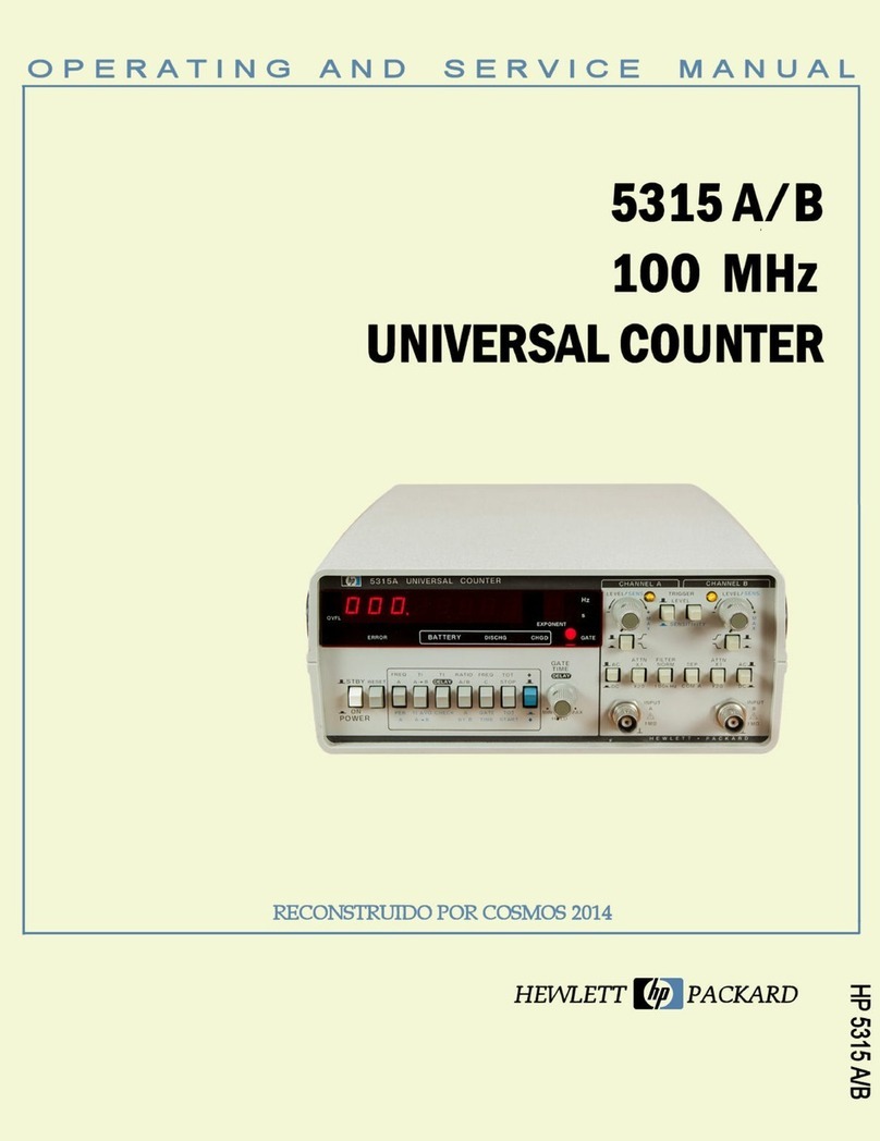
HP 5315 A Operating and service manual
