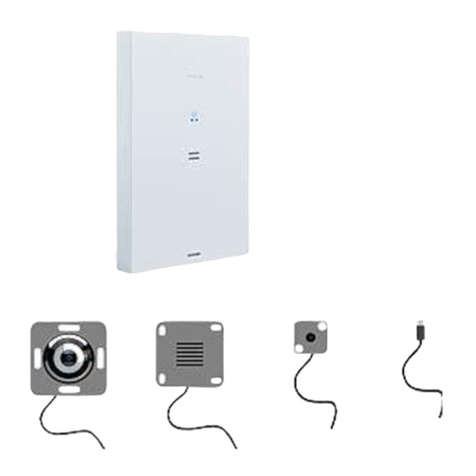
Florite N920 Series Setup guide

D10140-011817
Florite International, Inc.
N920 Series Instrument Training Guide
Instrument Training Guide
N920 Series
P ro c e s s C o ntr o l b y De s i gn

D10140—021709
Connect input or output into in-
strument port as shown
When the analog output option is
installed then plug the cable into
the REM jack and connect the
wires shown to the controlled
equipment.
When the relay output option is
installed then plug the output ca-
ble into the REM jack and con-
nect the wires shown to the con-
trolled equipment.
When you unit is installed with
the WAN modem option then
plug either end of an RJ-11 cable
into the corresponding jack and
the other end of the cable into a
standard telephone jack as
shown.
Plug the D9 part of the RS-232
connector into a computer serial
port. Insert the plug on the other
end of the cable into he PGM
jack as shown.
Insert power plug into PWR jack
as shown
Installation Instruction

D10140—021709
Press the CHAN button until reaching Input Port 1 (note: a 1 will be lo-
cated in the upper right hand corner of the display).
Pulse Output Sensors
Press the PROG button until reaching the Pulse Constant screen followed
by setting the number to correspond to the sensors number of pulses per
quantity. After setting the sensors Meter Constant again press the PROG
button to save the value.
Analog Output Sensors
Press the PROG button until reaching the Low Value screen followed by
setting the numbers for the lowest analog input level. Then press the
PROG button until reaching the Low Units screen and set the numbers for
the lowest measurement units that the Low Value represents.
Press the PROG button until reaching the High Value screen, followed by
setting the numbers for the highest analog input level. Then press the
PROG button until reaching the High Units screen and set the numbers for
the highest measurement units that the High Value represents.
Press the VIEW key to return to the main screen.
To program the units of measure press the PROG button until reaching the
Measure Units screen.
Quick Programming Instructions

D10140—021709
900 Series Instrument
• Keypad & Functions
• Lamp Indicators
• Navigation & Structure
• Programming Navigation
• Viewing Navigation
• Optional Configuration

D10140—021709
Instrument Keypad & Functions

D10140—021709
Lamp Indicators

D10140—021709
900 Series
Instrument Navigation & Structure


D10140—021709
900 Series
Instrument Programming Navigation


Network Address - System Program
Function
This screen is used to program the base address for serial communication programming and
information reporting.
Navigation
Access this screen by pressing the CHAN key until reaching the "Sys" port - and then pressing the
PROG key until reaching the desired screen. Note the first character field blinks indicating readiness
for programming.
Select
Field - by pressing either the QTY (right) or CHAN (left) key.
Character - change by pressing either the ZERO (down) or RATE (up) key.
Program - save new value by pressing the PROG key.

Report Start - System Program
Function
This screen is used to program the date and time that scheduled value reports for each input port
having Comm Port appropriately set are to then be sent. It is comprised of a date field and a 24 hour
clock time field.
Navigation
Access this screen by pressing the CHAN key until reaching the "Sys" port - and then pressing the
PROG key until reaching the desired screen. Note the first character field blinks indicating readiness
for programming.
Select
Field - by pressing either the QTY (right) key.
Character - change by pressing RATE (up) key.
Program - save new value by pressing the PROG key.

Reporting Frequency - System Program
Function
This screen is used to program the rate at which measurement information is send for each input port
having its Comm Port set. It is comprised of a three character numeric field and a time field.
Navigation
Access this screen by pressing the CHAN key until reaching the "Sys" port - and then pressing the
PROG key until reaching the desired screen. Note the first character field blinks indicating readiness
for programming.
Select
Field - by pressing either the QTY (right) or CHAN (left) key.
Character - change by pressing either the ZERO (down) or RATE (up) key.
Program - save new value by pressing the PROG key.

Alarm and Report Phone Numbers - System Program
Function
These screens are used to program the phone numbers to remotely access computers and data
collection equipment to report either one or more alarm conditions, or to send scheduled
measurement information from input ports having their Comm Port appropriately set.
Should an alarm condition occur without the alarm number programmed - the alarm will be sent to the
report phone number to insure alarm information is reported. When scheduled reports are enabled -
alarm information will be sent along with the value report which will be delayed by the programmed
Report Frequency.
Navigation
Access these screens by pressing the CHAN key until reaching the "Sys" port - and then pressing the
PROG key until reaching the desired screen. Note the first character field blinks indicating readiness
for programming.
Select
Field - by pressing either the QTY (right) or CHAN (left) key.
Character - change by pressing either the ZERO (down) or RATE (up) key.
Program - save new value by pressing the PROG key.

Answer Rings - System Program
Function
This screen is used to program the number of public switched telephone system rings after which the
ringing line is answered by the instrument. The line will not be answered if set to zero. This function is
often used for maintenance, diagnostic, and general remote access purposes.
Navigation
Access this screen by pressing the CHAN key until reaching the "Sys" port - and then pressing the
PROG key until reaching the desired screen. Note the first character field blinks indicating readiness
for programming.
Select
Field - by pressing either the QTY (right) or CHAN (left) key.
Character - change by pressing either the ZERO (down) or RATE (up) key.
Program - save new value by pressing the PROG key.

Log Records - System View
Function
This screen is used to view the number of data records that have been logged. This screen is also
used to completely control the logging functions including start, stop, upload and zero records.
Navigation
Access this screen by pressing the CHAN key until reaching the "Sys" port - and then pressing the
VIEW key until reaching the desired screen. Note the first character field blinks indicating readiness
for programming.

Network Address - System View
Function
This screen is used to view the instruments programmed communication base address.
Navigation
Access this screen by pressing the CHAN key until reaching the "Sys" port - and then pressing the
VIEW key until reaching the desired screen. Note the first character field blinks indicating readiness
for programming.

Date-Time - System View
Function
This screen is used to view the real time clocks date and time having a 24 hour clock time field.
Navigation
Access this screen by pressing the CHAN key until reaching the "Sys" port - and then pressing the
VIEW key until reaching the desired screen. Note the first character field blinks indicating readiness
for programming.

Next Report Date-Time - System View
Function
This screen is used to view the date and time that a next regularity scheduled value report is to be
sent.
Navigation
Access this screen by pressing the CHAN key until reaching the "Sys" port - and then pressing the
VIEW key until reaching the desired screen. Note the first character field blinks indicating readiness
for programming.
Table of contents
