Flourish TrimLine 10' x 20' User manual

The TrimLine 10' x 20' Canopy
Parts List
This page contains a list of all the parts you should receive for your TrimLine Canopy. Parts for optional
components are listed with separate instructions for those options. Please review all parts to be sure you
have everything you need. Should you nd anything missing, please call us immediately at: 1-800-296-0049
Page 1
(1) Topper (Roof)
Plastic Raer Poles
(14) Raer End sections - with metal connector on one end
(7) Raer Center sections
(6) Sidewalls 10 wide x 7 high
Joints
(4) Tie-down Screws
(8) 10” Steel Spikes
(14) Ball Bungees for bundling poles
(26) Thumbscrews (includes 1 spare)
Hardware
(2) Corner Joints ATL4 L
LeSide Raer Base
(2) Corner Joints ATL4 R
Right Side Raer Base
(2) 4-Way Raer Bases
ATL5
(8) Raer Bases
ATT
(2) Ridge Pole Supports
TLR
(1) 2-Way Ridge Support
TLR2
(3) Tee Joints
TL202
(6) Feet
AT211
(2) StaBar 3-Ways
AT200
(2) StaBar Ells
AT202
(1) StaBar Tee
AT210
(over, please)

(Parts List Continued)
Metal Poles
(4) Upper Horizontal female sections – 58 ¼” long, coded purple
(4) Upper Horizontal male sections – 61” long, coded purple
(9) Horizontal female sections – 58 ¼” long, no color code
(9) Horizontal male sections – 61” long, no color code
*Male and female sections click together to form (9) identical 116 ½” poles, no color code
(3) Gable Risers – 26” with snap buons at both ends
(6) Telescoping Leg Assemblies – lower section is nested inside upper section
(For 8 wall height you will also receive 15” Upper Leg Extenders)
(For 9 wall height you will also receive 27” Upper Leg Extenders)
Page 2
*Male and female sections click together to form (4) 116 ½” poles, coded purple

TRIMLINE CANOPY 10' x 20'
Instructions for Assembly
Before beginning assembly of your TrimLine, please take time to review the enclosed Parts List
to familiarize yourself with the TrimLine and to conrm that all parts are present.
Also, review these instructions along with the instructions for any accessories or options you have
purchased, such as Awning or Rear Door assemblies. Parts for TrimLine accessories oen need to
be installed during set up of the canopy. Reviewing all instructions before beginning set up will
help ensure that you have the necessary accessory parts in place as you set up your TrimLine.
***The TrimLine Canopy can be set up by one person, but as with any canopy
set up is easiest with a lile help!
Visit our website to see all options available for the TrimLine Canopy: www.ourish.com
Please, assemble the TrimLine at home the rst time, not at an event.
Video instructions are available on our website!
Go to: www.ourish.com/instructions or scan this code with your QR Code
Reader App for a direct link to our instructions and videos.
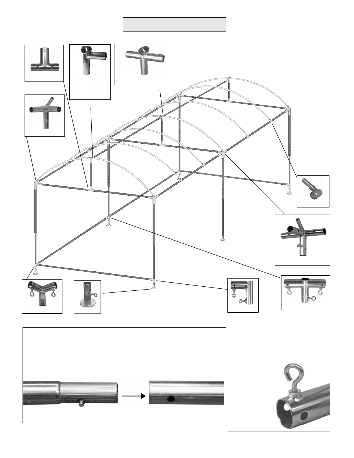
FRAME OVERVIEW
Joining Pole Sections:
Pole sections click together. Take care to join purple coded male
poles to purple coded females, and no-color code males to no-
color code females. Telescoping legs arrive nested together with
the boom section inside the top section.
Male Female
Tee Joint 2 Way Ridge Support
Corner Joint
Foot StaBar Ell StaBar Tee
Raer Base
*Before beginning assembly for
the rst time, take a moment to
start thumbscrews on all joints
equipped with
a receiving nut.
2
4 Way Raer Base
StaBar 3 Way
Ridge Support
(Arrow must
point DOWN)

ASSEMBLY OF ROOF FRAME
1. Begin by clicking together the male and female purple coded sections to form four 10 poles.
2. Slide Raer Base Joints onto the purple coded poles, clicking onto the snap buons located midway
on each section. Be sure all Raer Base stubs are pointed the same direction.
3. Now connect two of the poles to a 4 Way Raer Base and aach a Corner Joint to either end of the now
20 long pole. Repeat with the remaining two poles, keeping all Raer Base Stubs pointing the same
direction. You now you have two 20 long poles with Raer Base Stubs facing each other.
Quick Tip: Vertical barrel of these
joints can be quickly identied by
the thumbscrew.
4. Click together no-color sections to form three 10 poles.
5. Now slide the Tee Joints to center of the no color poles and click into place. Take care to center the
joint over the seam where the pole sections connect.
6. Insert the no-color poles into the Corner Joints as shown below. The Raer Base Stubs should be
facing up and towards the center of the frame.
7. Add the short 26” riser poles to the Tee Joints and top them with the Ridge Support Joints at the
ends and the 2 Way Ridge Support at the center.
8. Click together the remaining no-color sections to form two 10 poles and insert into the Ridge
Support Joints to complete the assembly of the metal parts of the roof frame.
3
4 Way Raer Base
Purple Pole No-color Pole
Tee Joint
Ridge Support Joint
2 Way Ridge Support
Ridge Pole
Corner Joint
Raer Base
Center of pole
Snap into this hole
*Note - the 2 Way Ridge Support joint has two dierent snap buon hole
placements. Adjust the seing depending on the t of your canopy top
and the ease of aaching the ridge support poles.

RAFTERS
1. To assemble raers, slide each Raer End (with metal sleeve) onto a Raer Base Stub, keeping the
metal end up.
2. Slide three of the Raer Center sections through the Ridge Support Joints. The remaining Raer
Center sections will sit on top of the Ridge Pole.
3. To connect the Raer sections, simply push each plastic end of the center sections down and into
the corresponding metal end of the Raer Ends. Keep pushing down until you feel it pop into place.
4

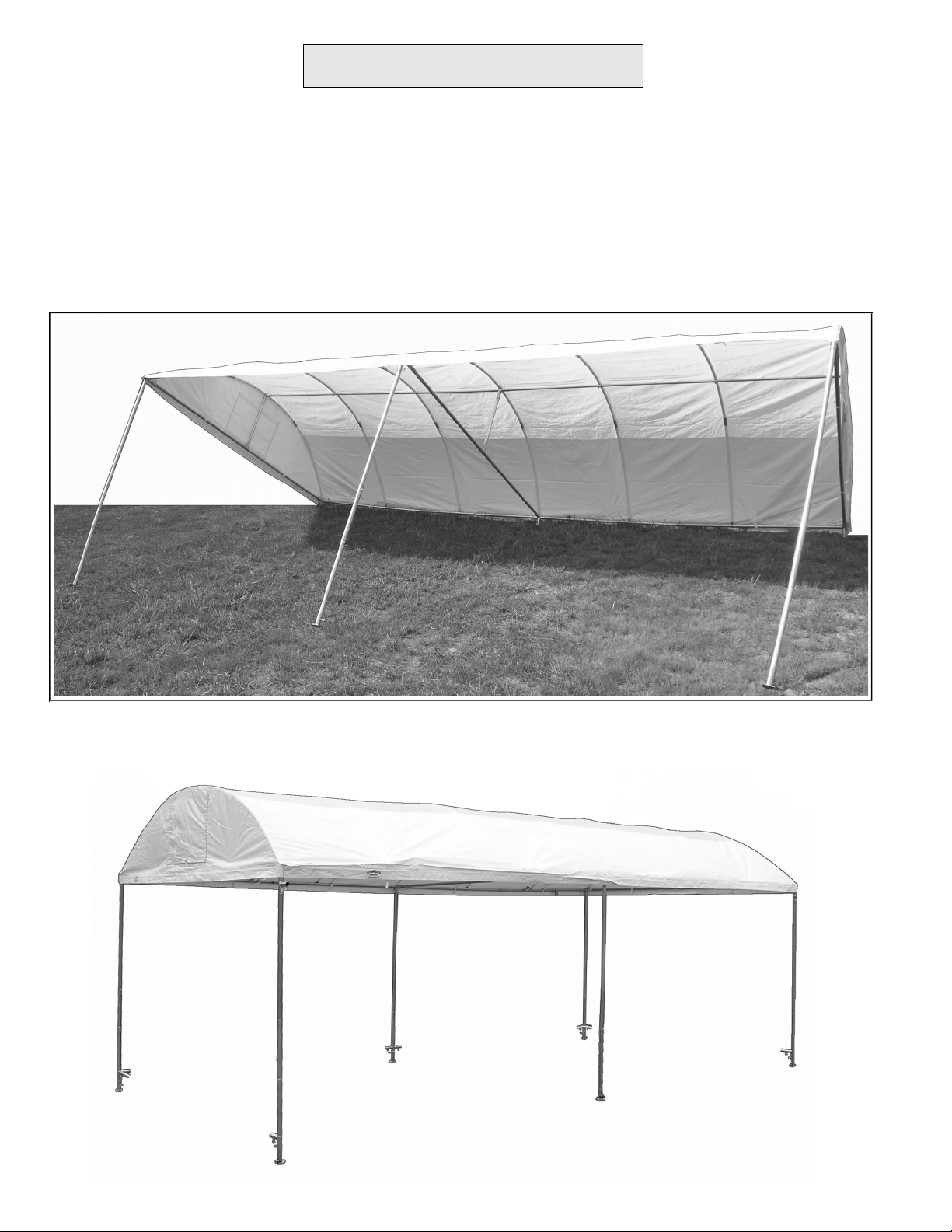
TOPPER
*Your canopy top has been folded for shipping in a way that makes it easy to set up. Please read
these directions before unfolding topper.
1. Beginning at one gable end of the roof frame, unroll top along the ridge poe, leing the ends hang
down over either end of the frame.
2. Unfold top, stretching it out over the entire roof frame and aligning the corners with the corner
joints of the frame.
*Instructions for re-folding the top at the end of the show can be found on page 9.
3. With the top stretched over the frame, lithe valance along the front edge and aach the Velcro
straps around the frame pole to hold the top in place as you lithe canopy. (The rest of the straps
will be easier to aach aer the legs are put in place.)
5
Vents: Now is the easiest time to access the heat/wind vents, although they may be opened or closed at
any time, from inside or outside the canopy. From the outside, simply roll up and secure against the
Velcro strips. From inside, separate the boom Velcro strip and reach through to roll up.
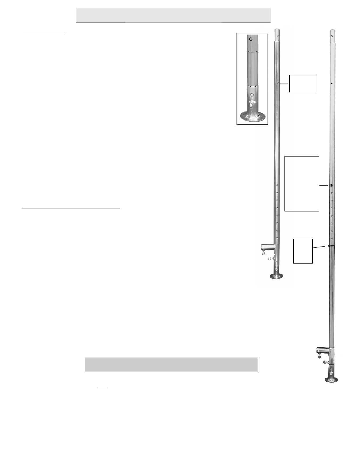
Initial Set Up
2. Find the hole located about 12” from the top of the leg and
keep pulling the boom section out until the snap buon clicks
into place; this is the “travel” position.
At this point the leg assemblies are ready for transport or storage.
If space allows, there is no need to remove joints between shows.
Extending the Legs for Use
2. With the top section resting on the “rest-stop” buon rotate sections
until a buon pops out of the topmost of the row of holes. This is the
extended position, 7 . high. To increase the height of the leg depress the
buon in the row of holes and extend to the desired height.
3. To collapse the leg, push in BOTH the “rest-stop” buon and the snap buon
in the row of holes. Rotate one section slightly to keep the snap buon from
catching. Re-engage the “travel” buon to secure for storage.
Travel
position
with
Foot
Extended
position,
7 .
1. To extend the leg, hold upright on the oor and step on the footplate to
keep the boom section in place. Lithe top section upwards until a snap
buon pops out from the boom section, just below the upper section. This
is the “rest-stop” position.
4. Slide feet onto the boom of each leg, rotating until the snap
buon on the leg snaps into the hole on the foot. Tighten the
thumbscrews on the feet – nger-tight only!
1. Begin by holding leg upright, with the row of holes towards
the boom of the leg. Line up the snap buon at the very boom
with the row of holes, then start pulling the inner nested section
of the leg out, just about 6” at rst.
Travel
position
with
StaBar
“Rest-
Stop”
Buon
“Travel”
Buon
Seing Up and Using the Telescoping Legs
3. Slide StaBar Joints onto boom section of legs, with the white
arrow pointing down. Refer to the illustration on page 8 for
correct placement.
6
*For ease of set-up, you may wish to insert the leg extenders into the canopy corner joints
before raising the top onto it's legs. When you lithe roof, you'll be inserting the legs into
the extenders rather than the corner joints.
Add Leg Extenders to the top of the telescoping legs. For the 8' height the extensions
measure 15” long, For the 9' height they measure 27” long.
Leg Extenders for 8' or 9' wall-height canopies
*At the minimum 7 height, you should have two snap buons showing; one in
the topmost adjustment hole and one buon in the boom leg section.
Height
Adjustment
Buon,
minimum
7 height
ATTACHING THE LEGS
1. Begin with the front (long edge) of your canopy. Lithe front edge and insert center leg into 4 Way
Raer Base. With this leg in place, you can walk to either end and aach the other two legs into the
Corner Joints.
2. With the front legs aached, step inside and nish aaching Velcro straps to the frame.
4. Lithe back edge now and repeat the process with the rear legs
7
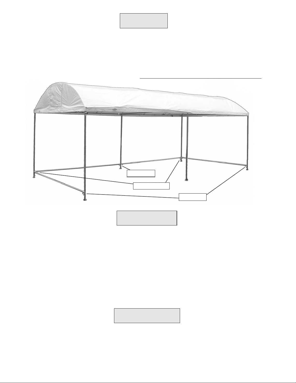
STABARS
1. Click together no color pole sections to form four 10 poles.
2. Insert poles into StaBar Joints, working along the back rst, then adding the sides.
3. Adjust StaBar Joints up or down along the legs to allow the StaBar to remain level even when the
legs are set at diering heights to compensate for uneven terrain.
4. Finally, tighten all thumbscrews on the frame. FINGER TIGHTEN ONLY – do NOT use tools!
1. Unfold walls, locating the top edge with roll up straps aached (the boom edge has grommets).
2. Standing inside the canopy, zip the sidewalls to the topper from leto right. Stepping outside
the canopy, zip sidewalls to each other at the corners. Use Velcro wind straps to aach wall to leg
when one or more wall has been removed or rolled up.
3. Pull topper snug at corners, overlapping and aaching Velcro aps at ends of valances.
*Note that the heavy duty zippers on the TrimLine are “self-lubricating”. They may be stiat rst
but will handle with ease aer a few uses.
ANCHORING
Whenever possible, use the TieDown Screws and Spikes included to aach canopy to the ground. If
neither is usable, we advise the use of our GreatWeights or other weight to keep you earthbound in
strong winds. Opening wind vents to release pressure is also helpful in windy conditions.
8
SIDEWALLS
StaBar Ells
StaBar 3 Ways
StaBar Tee
1. Release wind straps from legs, unzip and remove Sidewalls and fold
carefully. Store in optional short Carrying Bag.
2. Remove StaBars, starting with the sides.
4. To fold the topper, stand at the gable ends and unroll the heat/wind vents if you've had them open.
Now fold one edge up to the center, then the other side, and nally fold in half along the center. The
topper should now be folded in a long packet siing along the ridgepole. Keeping it on the ridgepole
to keep it clean, start rolling at one end and nish with a cylinder shape that can be stored in the
optional long Carrying Bag.
5. To pull the raers othe raer bases, stand inside the frame, place a foot on the horizontal purple
pole and pull up to release from Raer Bases and Corner Joints. Raer sections can now be separated.
6. The rest of the poles and joints can now be disassembled, starting with the ridgepole and working
your way down until you have pole sections that can be stored in the optional Pole Bags or bundled
with Ball Bungees.
3. Loosen thumbscrews and remove the rear legs, leaving the center leg until last.. With the rear legs
removed, you can step inside and remove the Velcro straps holding the topper onto the frame. Now
remove the front legs.
9
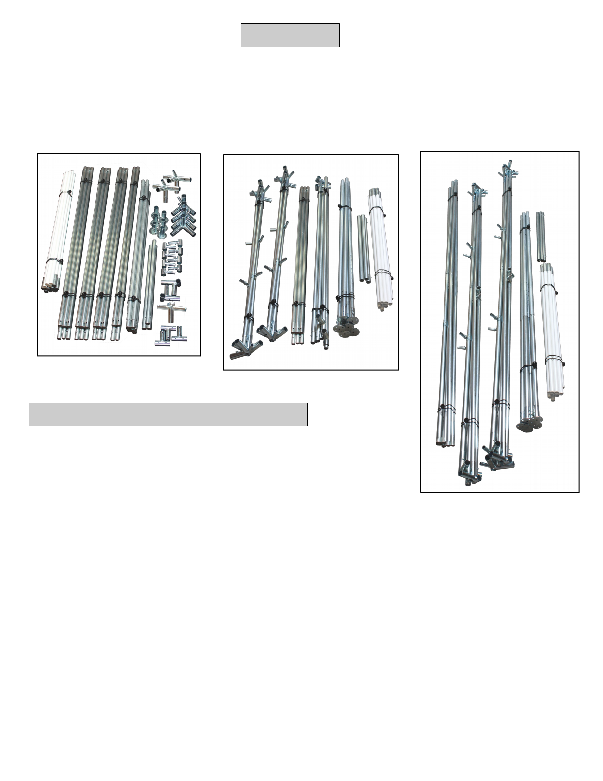
Step-by-step break down of the TrimLine
Packing Up
You may choose to break your canopy down to it's smallest component parts if packing space is tight,
but for ease of set up at your next show you may prefer to leave the hardware connected to the poles.
Most compact storage
All parts and poles fully
disassembled
Quicker set up
Hardware aached to poles,
Poles broken down to 5 . lengths
Fastest set up
Hardware aached to poles,
Poles leassembled at 10 .

Care and Feeding of your TrimLine Canopy
* Vinyl is a tough and durable fabric. It resists mildew and dirt but should receive your care and
aention to keep it in prime condition. DO NOT STORE WET. If you have had to break down wet,
remove canopy top and walls as soon as you get home and open up to allow it to dry thoroughly.
* The Ball Bungees are stretch cable loops with plastic balls that may be used to bundle the poles into
several easy to manage bundles. For easier and cleaner break down and storage, consider our Pole Bags.
* The Spikes and Tie Down Screws are intended for use on grass or dirt. On streets or other hard
surfaces you will need to use weight to anchor your canopy. Our optional GreatWeights are a great
way to add weight to the TrimLine.
*Dirt can be cleaned from walls, roof and awnings with any regular non-abrasive liquid household
cleaner. A sobrush may be used, if necessary. Always use glass cleaner on clear walls. Rinse well
to remove any cleaning product residue and dry thoroughly before storing.
You may choose to work on a clean patio surface, or set up the canopy roof frame only and stretch
the top over it for cleaning. A long-handled brush or mop can make it easier to reach.
This manual suits for next models
1
Table of contents
Other Flourish Tent manuals


