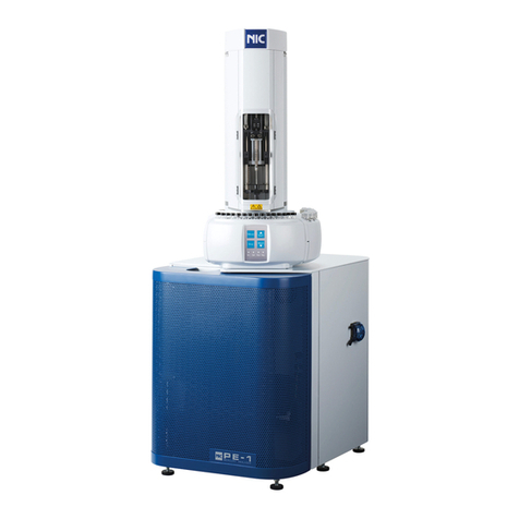
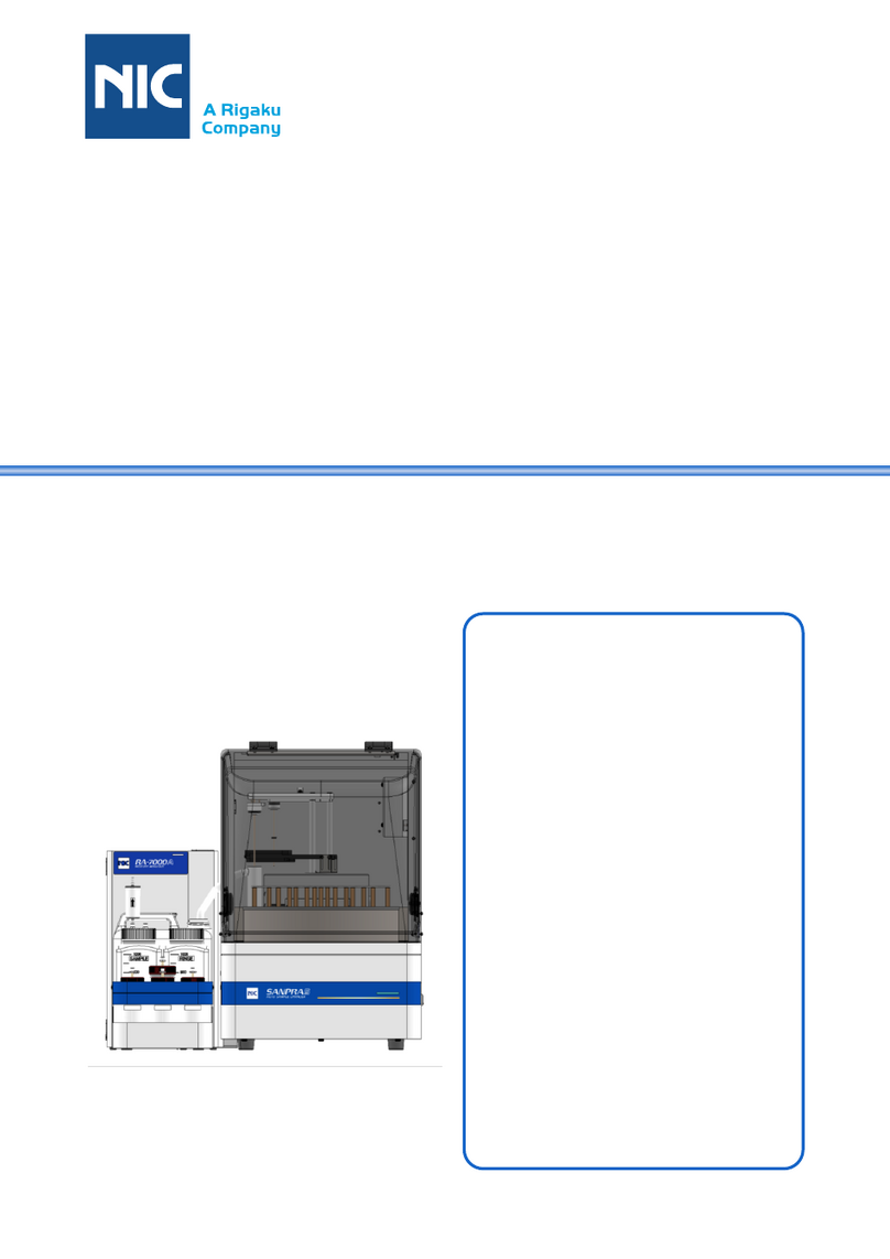
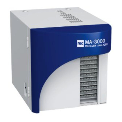
Nic MA-3 Solo User manual

Thermal Vaporization
Mercury Analyzer
MA-3 Solo
Instruction Manual
NIC-TD-0000090-15
Nippon Instruments Corporation

Instruction Manual: Thermal Vaporization Mercury Analyzer MA-3 Solo NIC-TD-0000090-15
Nippon Instruments Corporation
Table of Contents
1. Introduction ................................................................................................................. 1
1.1. Safety Precaution................................................................................................... 1
1.1.1. Meanings of Safety Alert Symbols .................................................................... 1
1.1.2. Cautions Concerning Installation ...................................................................... 1
1.1.3. Cautions Concerning Handling ......................................................................... 2
1.1.4. Cautions Concerning Storage ........................................................................... 3
1.1.5. Cautions Concerning Upgrade of PC Software and Firmware ......................... 4
1.1.6. Caution Concerning Disposal............................................................................ 4
2. Outline of Instrument.................................................................................................. 5
2.1. General Description ............................................................................................... 5
2.2. Principle of Measurement ...................................................................................... 6
2.3. External Appearance of Instrument ....................................................................... 7
2.3.1. Front and Rear .................................................................................................. 7
2.3.2. Right Side .......................................................................................................... 9
2.4. Inside of Instrument ............................................................................................. 10
2.4.1. Top................................................................................................................... 10
2.4.2. Front .................................................................................................................11
3. Installation and Connection..................................................................................... 12
3.1. Installation of Instrument...................................................................................... 12
3.2. Installation and uninstallation of PC Software ..................................................... 13
3.2.1. Installation Procedure for “MA3SoloWin”........................................................ 13
3.2.2. Installation of “COM_Class (MA3 Solo USB-SERIAL Driver)”........................ 15
3.2.3. Setup of Communication Port ......................................................................... 15
3.2.4. Uninstallation Procedure ................................................................................. 18
3.3. Upgrade of PC Software and Firmware............................................................... 19
3.3.1. Upgrading Procedure for Firmware................................................................. 19
3.3.2. Measures against Unsuccessful Firmware Updating...................................... 21
3.3.3. Upgrading Procedure for “MA3SoloWin” ........................................................ 23
4. Measurement ............................................................................................................. 24
4.1. Measurement Flowchart ...................................................................................... 24
4.2. Necessities for Measurement .............................................................................. 25
4.3. Articles Recommended for Measurement ........................................................... 25
4.4. Preparation for Measurement .............................................................................. 26
4.4.1. Preparation of Standard Mercury Solution...................................................... 26

Instruction Manual: Thermal Vaporization Mercury Analyzer MA-3 Solo NIC-TD-0000090-15
Nippon Instruments Corporation
4.4.2. Blank Process of Sample Boat........................................................................ 27
4.4.3. Blank Process of Mercury Collector Tube (Gas Measurement Option).......... 28
4.4.4. Blank Process of Addictive B .......................................................................... 29
4.4.5. Sampling method for Collector tube................................................................ 30
4.4.5.1. Standard gas ........................................................................................... 30
4.4.5.2. Samples in the Tedlar®bag ..................................................................... 31
4.4.5.3. Ambient air .............................................................................................. 31
4.5. Operational Procedure for Measurement ............................................................ 32
4.5.1. Startup of MA-3 Solo ....................................................................................... 32
4.5.2. Self Check ....................................................................................................... 34
4.5.3. Setup of Measurement Condition.................................................................... 37
4.5.4. Setup of Table Condition ................................................................................. 37
4.5.5. Setup of Method .............................................................................................. 38
4.5.6. Creation of Calibration Curve.......................................................................... 38
4.5.6.1. Registration of Calibration Curve Table .................................................. 38
4.5.6.2. Setting of Sample .................................................................................... 39
4.5.6.3. Measurement Start.................................................................................. 40
4.5.6.4. Suspension of Measurement .................................................................. 41
4.5.6.5. Termination of Measurement................................................................... 41
4.5.6.6. Checking of Calibration Curve ................................................................ 42
4.5.7. Unknown Sample Measurement ..................................................................... 43
4.5.7.1. Measuring of Sample .............................................................................. 43
4.5.7.2. Registration of Unknown Samples.......................................................... 44
4.5.7.3. Setting of Sample .................................................................................... 48
4.5.7.4. Special Operating Procedure (For UOP Method 938-20)....................... 53
4.5.7.5. Measurement Start.................................................................................. 56
4.5.7.6. Suspension of Measurement .................................................................. 56
4.5.7.7. Termination of Measurement................................................................... 56
4.5.7.8. Checking of Measurement Result........................................................... 56
4.5.8. Printing ............................................................................................................ 57
4.5.9. Shutdown Operation........................................................................................ 59
5. Control and Analysis Software MA3SoloWin......................................................... 60
5.1. Constitution of Menu ............................................................................................ 60
5.2. Main Menu ........................................................................................................... 61
5.2.1. New.................................................................................................................. 62
5.2.2. Open................................................................................................................ 62
5.2.3. Save as............................................................................................................ 62

Instruction Manual: Thermal Vaporization Mercury Analyzer MA-3 Solo NIC-TD-0000090-15
Nippon Instruments Corporation
5.2.4. Template .......................................................................................................... 63
5.2.4.1. Open Template File ................................................................................. 63
5.2.4.2. Save as Template File ............................................................................. 63
5.2.5. Print ................................................................................................................. 64
5.2.5.1. Print ......................................................................................................... 64
5.2.5.2. Page Setup.............................................................................................. 65
5.2.5.3. Print Preview ........................................................................................... 66
5.2.6. Setting.............................................................................................................. 66
5.2.6.1. System Setup .......................................................................................... 66
5.2.6.2. Calibration Curve Setting ........................................................................ 68
5.2.6.3. Sample Name Registry ........................................................................... 69
5.2.6.4. Reset Window Size ................................................................................. 69
5.2.6.5. Manufacturer Setup................................................................................. 69
5.2.7. About ............................................................................................................... 69
5.2.8. Exit................................................................................................................... 69
5.3. Self Check Screen ............................................................................................... 70
5.3.1. Constitution of Screen ..................................................................................... 70
5.3.2. Sequence ........................................................................................................ 72
5.4. Measurement Screen........................................................................................... 76
5.4.1. Input / Output Screen ...................................................................................... 77
5.4.2. Ribbon Menu ................................................................................................... 80
5.4.2.1. START ..................................................................................................... 80
5.4.2.2. STOP ....................................................................................................... 80
5.4.2.3. NEXT ....................................................................................................... 81
5.4.2.4. PURGE.................................................................................................... 81
5.4.2.5. Method..................................................................................................... 82
5.4.2.6. Measure Cond......................................................................................... 84
5.4.2.7. Table Cond. ............................................................................................. 87
5.4.2.8. HEIGHT/AREA ........................................................................................ 90
5.4.2.9. DRIFT ON/OFF ....................................................................................... 91
5.4.3. Status Indicator................................................................................................ 92
5.5. Analysis Screen ................................................................................................... 93
5.5.1. Constitution of Screen ..................................................................................... 93
5.5.2. Operation on Table Screen.............................................................................. 94
5.5.3. Ribbon Menu ................................................................................................... 95
5.5.3.1. STATS...................................................................................................... 95
5.5.3.2. Width Reset ............................................................................................. 95

Instruction Manual: Thermal Vaporization Mercury Analyzer MA-3 Solo NIC-TD-0000090-15
Nippon Instruments Corporation
5.5.3.3. Log Display.............................................................................................. 95
5.5.3.4. Input S. Vol .............................................................................................. 95
5.5.3.5. No. OF PROFILE .................................................................................... 96
5.6. Maintenance Screen ............................................................................................ 96
5.6.1. Leak Check...................................................................................................... 96
5.6.2. GLP Counter.................................................................................................... 97
5.6.3. Optical Adjust................................................................................................... 97
5.6.4. Parameters ...................................................................................................... 98
5.6.5. Hardware Check.............................................................................................. 98
5.6.6. Cooling ............................................................................................................ 99
5.6.7. Firmware Update............................................................................................. 99
5.6.8. Open LOG Files............................................................................................... 99
5.7. Formulae ............................................................................................................ 100
5.7.1. Calibration Curve........................................................................................... 100
5.7.1.1. Linear Formula (y = ax + b)................................................................... 100
5.7.1.2. Cubic Formula (y = ax3 + bx2 + cx + d)................................................ 100
5.7.2. Mercury Quantity in Standard Gas................................................................ 102
6. Maintenance ............................................................................................................ 103
6.1. Daily Inspection.................................................................................................. 103
6.2. Yearly Inspection................................................................................................ 104
6.3. Recommended Replacement Components....................................................... 105
6.4. Errors and Warnings .......................................................................................... 106
6.5. Troubleshooting.................................................................................................. 109
6.5.1. Fall of Sensitivity ........................................................................................... 109
6.5.2. Abnormal Blank Value ....................................................................................110
6.6. Maintenance Work ..............................................................................................111
6.6.1. Leak Check.....................................................................................................111
6.6.2. Procedure for Opening Top Cover .................................................................114
6.6.3. Removal of Sample Heating Tube and Mercury Collector Tube....................115
6.6.4. Fixing of Sample Heating Tube and Mercury Collector Tube ........................117
6.6.5. Replacement and Cleaning of Boat In/Out Rod............................................ 121
6.6.6. Greasing of Inlet ............................................................................................ 123
6.6.7. Removal and Fixing of Absorption Cell ......................................................... 124
6.6.8. Cleaning of Absorption Cell and Joints ......................................................... 125
6.6.9. Adjustment Procedure for Optical System .................................................... 126
6.6.10. Replacement of Tubes .................................................................................. 126
6.6.11. Replacement of Valves V1 and V2................................................................ 130

Instruction Manual: Thermal Vaporization Mercury Analyzer MA-3 Solo NIC-TD-0000090-15
Nippon Instruments Corporation
6.6.12. Replacement of Valve V3 .............................................................................. 131
6.6.13. Replacement of Air Pump.............................................................................. 132
6.6.14. Replacement of Activated Carbon Filter ....................................................... 133
6.6.15. Replacement of Flow Adjustment Valve........................................................ 134
7. Detailed System Specification............................................................................... 135
7.1. Thermal Vaporization Mercury Analyzer MA-3 Solo.......................................... 135
7.1.1. Specification of MA-3 Solo Main Unit............................................................ 135
7.1.2. Control and Data Processing Unit................................................................. 136
7.1.3. External Connection Function ....................................................................... 136
7.1.4. Automatic sample weight entry function by the balance............................... 136
7.1.5. Dimensions and Weight ................................................................................ 136
7.1.6. Power Supply ................................................................................................ 137
7.1.7. Standard Accessories.................................................................................... 137
7.2. Options............................................................................................................... 138
7.2.1. Mercury Collector Tube Measurement Kit..................................................... 138
7.2.2. AQUA kit for MA-3 Solo................................................................................. 138
7.2.3. Sample boat – Large sized (Metal) ............................................................... 138
7.2.4. Recommended Spare Parts.......................................................................... 138
8. Installation Requirements...................................................................................... 139
8.1. Installation Environment..................................................................................... 139
8.2. Power Requirements ......................................................................................... 139
8.2.1. Instrument Main Unit ..................................................................................... 139
8.2.2. PC and Optional Printer ................................................................................ 139
8.3. Measures against Electric Noise ....................................................................... 139
8.4. Other Requirements........................................................................................... 140
8.5. Instrument Layout .............................................................................................. 140
9. Warranty................................................................................................................... 141
9.1. Warranty Period ................................................................................................. 141
9.2. Warranty Conditions........................................................................................... 141
10. Cautions Concerning Disposal of Analyzer......................................................... 141
11. Appendix.................................................................................................................. 142
11.1. Flow in Measurement Path ................................................................................ 142
11.1.1. Atomize (Without Humidification) Path ......................................................... 142
11.1.2. Atomize (With Humidification) Path............................................................... 143
11.1.3. Purge/Measure/Meas Purge Path................................................................. 144
12. Contact..................................................................................................................... 145


Instruction Manual: Thermal Vaporization Mercury Analyzer MA-3 Solo NIC-TD-0000090-15
Nippon Instruments Corporation 1
1. Introduction
1.1. Safety Precaution
For the safe use of this product, observe the following precaution:
In no event shall Nippon Instruments Corporation, Inc. be liable for any direct,
indirect, punitive, incidental, special consequential damages, to property or life,
whatsoever arising out of or connected with the use or misuse of our products.
Refer to the attached documents for the optional reagent dispenser and sample changer.
Danger
Indicates that incorrect handling could result immediately in death or
severe injury to the operator.
Warning
Indicates that incorrect handling could result in death or severe injury
to the operator.
Caution
Indicates that incorrect handling could result in moderate or minor
injury to the operator or damage to property.
Danger
Do not put any inflammable or combustible around the instrument.
Otherwise, a fire may result.
Warning
If there is any risk of generation of any harmful gasses such as
halogen, sulfur and selenium during decomposition by heating, please
be sure to vent the exhaust gas.
Caution
Be sure to use the supplied power cable.
If another cable is used, it may cause a failure.
Observe installation requirements and power specifications.
Otherwise, a failure may result.
Install the instrument on a horizontal working table with sufficient
strength.
Otherwise, a failure or a minor injury caused by an overturn or a
fall may result.
Secure space of 150 mm or more in the rear for hot exhaust
(general exhaust) from the rear upper part of the instrument and
work space to turn on or off the instrument.
Be sure to avoid a room for using an organic chlorine solvent or a
halogen reagent such as potassium iodide.
Also avoid a room into which the gas of the above-mentioned
reagent may flow.
Such substances become the cause of trouble such as the
sensitivity fall of the instrument.

Instruction Manual: Thermal Vaporization Mercury Analyzer MA-3 Solo NIC-TD-0000090-15
2 Nippon Instruments Corporation
Warning
The area near the inlet is hot.
Put on protectors such as heat-resistant gloves, and take care not
to get burned.
Never disable the solenoid lock manually during a measurement
because it is very dangerous.
When handling a sample boat or a mercury collector tube for a
measurement or the like, take care not to get burned.
When handling, put on protectors such as heat-resistant gloves,
and use boat tongs.
After washing the sample boat, first dry it at about 100C. Then,
heat at a high temperature to lower the blank. Heating a wet boat
to high temperatures can damage the sample boat.
Hot exhaust (general exhaust) is discharged from the rear upper
part of the instrument.
Take care not to get burned.
When touching the instrument for maintenance, make sure that it
has been cooled sufficiently.
When touching, put on protectors such as heat-resistant gloves.
Otherwise, you may get burned.
When the instrument is turned off, the surface temperature can be
high due to the heat from the heater.
Be cautious about burn injuries and do not place anything on the
instrument.
Take care that there is no dust on the filter of the fan in the rear.
If the filter is clogged, it will cause the abnormal temperature rise
of the instrument, which is very dangerous.
Before using a reagent, procure and administer the safety data
sheet (SDS).
Disconnect the power cable from the instrument before
maintenance work.
Otherwise, an electric shock or a failure caused by a short circuit
may result.
Do not measure directly sample decomposed using nitric acid.
Otherwise, the activated carbon filter on the exhaust side may
generate heat.
Dilute nitric acid to 5 wt% or less.

Instruction Manual: Thermal Vaporization Mercury Analyzer MA-3 Solo NIC-TD-0000090-15
Nippon Instruments Corporation 3
Caution
Do not disassemble or modify the instrument without permission.
Otherwise, a failure may result.
Use the instrument after reading this document carefully.
Otherwise, a failure caused by an operational mistake may occur.
Observe the range of specifications. If the instrument is used out
of the specification range, a failure may occur.
The inlet is locked while the instrument is turned off and during
the measurement, self check and leak check.
Do not open the inlet while it is locked.
The inlet can be damaged.
When touching a glass component, take care not to suffer an
injury such as cutting a hand.
Use neutral detergent to clean the holder exclusively for the
collector tube that is used for the measurement of the mercury
collector tube, and put on (heat-resistant) gloves or the like when
touching it so that oil does not stick to it.
Otherwise, it will rust and deteriorate sooner.
Caution
After the termination of a measurement, be sure to remove water in
the drain bottle and humidification bottle.
Otherwise, the sample heating tube in the instrument may absorb
moisture and be clogged.
Also when the instrument is not used for a long time, the sample
heating tube in the instrument may absorb moisture in the air and
be clogged.
Start up the instrument every two weeks or remove the sample
heating tube and keep it in a desiccator or the like so that it does
not absorb moisture.

Instruction Manual: Thermal Vaporization Mercury Analyzer MA-3 Solo NIC-TD-0000090-15
4 Nippon Instruments Corporation
Caution
When upgrading is carried out, upgrade the firmware first and then
the PC software.
If the sequence is reverse, installation may not be carried out
normally.
Never turn off the PC or instrument during the update of the
firmware.
Never disconnect the USB cable.
Otherwise, a failure may result.
Caution
If the instrument is discarded inadequately, environmental pollution or
personal damage may result.

Instruction Manual: Thermal Vaporization Mercury Analyzer MA-3 Solo NIC-TD-0000090-15
Nippon Instruments Corporation 5
2. Outline of Instrument
2.1. General Description
The thermal vaporization mercury analyzer MA-3 Solo is an instrument that measures
mercury quantities contained in liquid samples such as wastewater and crude oil and
solid samples such as coal and soil rapidly, with high sensitivity and with high
precision.
By using an option, the measurement of metal mercury in gas is also possible.
It has a simple instrument configuration and user-friendly software design and is
optimum as an entry-level instrument for mercury measurements.

Instruction Manual: Thermal Vaporization Mercury Analyzer MA-3 Solo NIC-TD-0000090-15
6 Nippon Instruments Corporation
2.2. Principle of Measurement
A sample is heated in the H1 (sample heater), and the mercury compound in the
sample is made to evaporate. Then, the catalyst furnace (H2) decomposes a mercury
compound in gas, removes interfering components and atomizes mercury.
The interfering components are removed by managing the mercury collector tube to an
appropriate temperature using the H3, and the collection concentration is carried out
selectively for the mercury gas as gold amalgam.
After the completion of the sample heating decomposition sequence, the mercury
collector tube is heated, mercury is separated again as metal mercury gas and is led to
the detection unit (absorption cell), and the absorbance at 253.7 nm, which is the first
absorption wavelength band of mercury, is measured.
Heater H3
(Mercury Collector Tube
Heating Furnace)
Mercury
Collector Tube
Heater H2
(Catalyst Furnace)
Heater H1
(Sample Heating Furnace)
Heater H4
Detector
Absorption
Cell
Lamp
Detector
Drain Bottle
Humidifica-
tion Bottle
Needle Valve
Air Pump
Flow Sensor
Activated
Carbon Filter
Activated Carbon Filter
Nafion Tube
Exhaust
Air
Filter Unit

Instruction Manual: Thermal Vaporization Mercury Analyzer MA-3 Solo NIC-TD-0000090-15
Nippon Instruments Corporation 7
2.3. External Appearance of Instrument
1
2
3
4
7
6
8
9
5
11
10

Instruction Manual: Thermal Vaporization Mercury Analyzer MA-3 Solo NIC-TD-0000090-15
8 Nippon Instruments Corporation
* Statuses displayed by the status display lamp are as follows:
No.
Name
Description
1
Top cover
Opened in the case of maintenance work.
2
Side cover
Opened at the time of a measurement.
3
Status display lamp
The instrument status is displayed.
4
Front cover
Opened in the case of the upgrading of the firmware.
5
I/F connector
Used for connection to optional equipment.
6
USB Port
Used for connection to the PC.
7
Power switch
Houses an earth leakage breaker.
8
AC inlet
Used to connect the supplied power cable.
9
Rear fan
Equipped with a mesh cover.
10
Exhaust port
A tube with an outside diameter of 6 mm is used.
11
Inlet
Port to let in carrier gas.
Status
Status of Status Display Lamp
Description
Offline
Blinks at intervals of 1 sec.
The PC and instrument are not
communicating.
Maintenance
Blinks at intervals of 1 sec.
Any of the ribbon menu on the
“Maintenance” screen is being executed.
Ready
Turned on
Ready (normal) status.
Measuring
Blinks at intervals of 0.1sec.
During a sample measurement.
Error
Blinks at intervals of 0.3 sec. The
number of blinks is the same as
the error code number.
* The interval between the series
of blinks is 3 sec.
An error has occurred.

Instruction Manual: Thermal Vaporization Mercury Analyzer MA-3 Solo NIC-TD-0000090-15
Nippon Instruments Corporation 9
* Shown below is the instrument with the side cover opened:
No.
Name
Description
1
Flow adjustment valve
The flow rate can be adjusted by turning the knob.
2
Humidification bottle
When pure water is poured into the bottle, the carrier gas is
made to contain saturated steam.
3
Drain bottle
Effluent produced during a measurement is stored.
4
Inlet knob
When this is turned clockwise, the inlet is closed.
5
Inlet
This is where a sample is loaded.
6
Solenoid lock
Locked during a measurement so that the inlet is not opened
erroneously.
1
2
3
4
6
5

Instruction Manual: Thermal Vaporization Mercury Analyzer MA-3 Solo NIC-TD-0000090-15
10 Nippon Instruments Corporation
2.4. Inside of Instrument
* Shown below is the instrument with the top cover, side cover and inlet opened:
No.
Name
Description
1
Boat in/out rod
By supporting and inserting a boat, the inside of the system is
sealed.
2
Heater H1
Heats sample.
The fan has been installed in the lower part for cooling after a
measurement.
3
Heater H2
Heats an oxidation catalyst and an acid gas remover.
4
Thermostat
Turns off the power to heaters H1 and H2 when H2 overheats.
5
Heater H3
Controls the temperature of the mercury collector tube.
The fan has been installed in the lower part for cooling after a
measurement.
6
Heater H4
Heats the absorption cell to 150C.
2
1
3
5
4
6

Instruction Manual: Thermal Vaporization Mercury Analyzer MA-3 Solo NIC-TD-0000090-15
Nippon Instruments Corporation 11
* Shown below is the instrument with the top cover, side cover, front cover and inlet opened:
No.
Name
Description
1
Optical system
Consists of the absorption cell, mercury lamp and detector.
2
Activated carbon filter
Activated carbon column to remove mercury in exhaust gas.
3
Valves V1 and V2
Valves to switch the decomposition path and measurement path.
4
Flow sensor
Sensor for flow control.
5
Nafion tube
Removes steam in exhaust gas.
6
Air Pump
Sucks in carrier gas.
7
Filter unit
Filter for protection of Flow sensor.
8
Valve V3
Switches ordinary gas and humidification gas.
9
Activated carbon filter
Removes mercury in carrier gas.
10
Main board
Controls the instrument.
2
1
3
4
5
6
9
7
10
8

Instruction Manual: Thermal Vaporization Mercury Analyzer MA-3 Solo NIC-TD-0000090-15
12 Nippon Instruments Corporation
3. Installation and Connection
3.1. Installation of Instrument
Danger
Do not put any inflammable or combustible around the instrument.
Otherwise, a fire may result.
Warning
If there is any risk of generation of any harmful gasses such as
halogen, sulfur and selenium during decomposition by heating, please
be sure to vent the exhaust gas.
Caution
Be sure to use the supplied power cable.
If another cable is used, it may cause a failure.
Observe installation requirements and power specifications.
Otherwise, a failure may result.
Install the instrument on a horizontal working table with sufficient
strength.
Otherwise, a failure or a minor injury caused by an overturn or a
fall may result.
Secure space of 150 mm or more in the rear for hot exhaust
(general exhaust) from the rear upper part of the instrument and
work space to turn on or off the instrument.
Be sure to avoid a room for using an organic chlorine solvent or a
halogen reagent such as potassium iodide.
Also avoid a room into which the gas of the above-mentioned
reagent may flow.
Such substances become the cause of trouble such as the
sensitivity fall of the instrument.
(1) Put the MA-3 Solo and PC in the installation position.
For installation requirements and an installation layout, refer to “8. Installation
Requirements”.
(2) Install necessary software according to “3.2 Installation and uninstallation of PC
Software”.
* Be sure to carry out Step (2) before Step (5).
Otherwise, the installation of software and control will be impossible.
(3) Connect the power cable to the AC inlet in the rear of the MA-3 Solo.
(4) Connect the power cable to an outlet with the ground.
(5) Connect the MA-3 Solo and the PC using a USB cable.
(6) Connect the exhaust port in the rear of the instrument to a draft or the like.
(7) To automatically measure the sample weight by using the balance, connect the
cable between the balance and PC.
* Please refer to the instruction manual of the balance for the detail of connection.
* The cable is not included. Please prepare separately.

Instruction Manual: Thermal Vaporization Mercury Analyzer MA-3 Solo NIC-TD-0000090-15
Nippon Instruments Corporation 13
3.2. Installation and uninstallation of PC Software
To use the MA-3 Solo, the following software is necessary.
Control and analysis software “MA3SoloWin”
Communication driver “COM_Class (MA3 Solo USB-SERIAL Driver)”
Carry out installation using the supplied setup CD-ROM according to the
procedures described below.
*If the OS language setting is not English (United States), please set to English
(United States).
*For the operational procedures for Windows and the PC main unit and the setup
procedures for peripheral devices such as the printer, refer to the manual of each
apparatus.
(1) Push the power button of the PC to start Windows.
(2) Insert the setup CD-ROM into the optical drive of the PC.
After clicking “Open folder to view files”, Double-click the "Install.bat" file in the CD-
ROM.
(3) When the “Welcome to the MA3SoloWin Setup Wizard” screen is displayed, click
“Next >”.
Table of contents
Other Nic Measuring Instrument manuals
