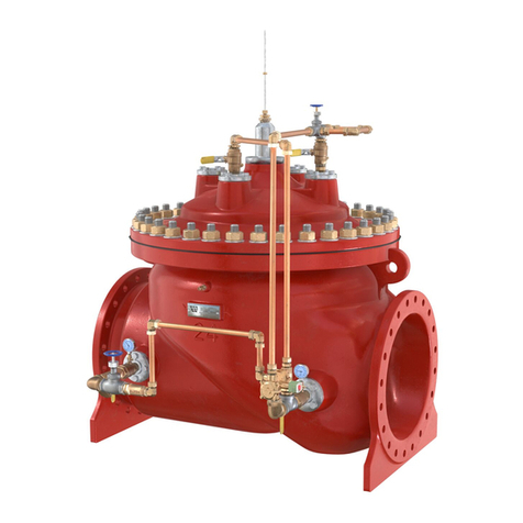
Flow Safe F7000 SERIES Instruction manual

High Performance Safety Relief Valves
F7000 / 8000 SERIES
PILOT-OPERATED
SAFETY RELIEF VALVE
INSTALLATION,
OPERATION, & MAINTENANCE MANUAL
Revision:
T
Date of Issue:
December 17, 2018
Approved by:
jwo
Engineering Projects Dir.

INSTALLATION, OPERATION, &
MAINTENANCE MANUAL
TITLE: F7000 / 8000 Series Rev. T
Pilot Operated Safety Relief Valve Page 2 of 43
TABLE OF CONTENTS
Topic Page
1.0 General ................................................................................................3
2.0 Description, Operation, Service Envelope, Installation, & Startup
2.1 Description / Operation ........................................................................5
2.2 Service Envelope .................................................................................5
2.3 Storage and Handling ..........................................................................6
2.4 Installation............................................................................................7
2.5 Remote Sense / Field Test Connection................................................8
2.6 Set Pressure Considerations for Backpressure ................................... 8
2.7 Startup .................................................................................................10
3.0 Main Valve Maintenance
3.1 Disassembly of the F7000/8000 Series Main Valve............................. 10
3.2 Reassembly of the F7000/8000 Series Main Valve.............................. 12
4.0 Pilot Valve Maintenance
4.1 F100 Pilot Valve ...................................................................................13
4.2 F200 Pilot Valve ...................................................................................15
4.3 F300 Pilot Valve, Diaphragm-Style (15 to 500 psig)............................. 17
4.4 F300 Pilot Valve, Piston-Style (286 to 6000 psig) ................................ 20
4.5 F500 Pilot Valve ...................................................................................23
5.0 Pilot Valve Set Pressure Adjustment
5.1 Definition / Tolerance............................................................................28
5.2 Pressure Adjustment / Verification........................................................28
5.3 F100 Pilot Valve Adjustment.................................................................30
5.4 F200 Pilot Valve Adjustment ................................................................30
5.5 F300 Pilot Valve Adjustment ................................................................31
5.6 F500 Pilot Valve Adjustment ................................................................32
5.7 Pilot Auxiliary Setter Adjustment ..........................................................33
6.0 Supplemental Testing and Accessories
6.1 Testing of the Main Valve Subassembly ..............................................34
6.2 Final Assembly Testing ........................................................................35
6.3 F300 Pilot Valve Proportional Band Adjustment................................... 35
6.4 Inservice Testing with the Field Test Connection................................. 36
6.5 Harguard Clean Pilot Supply Tank....................................................... 38
7.0 Troubleshooting Guide .......................................... ..............................39
8.0 Softgoods Kits
8.1 Main Valve Softgoods ..........................................................................40
8.2 Pilot Valve Softgoods .......................................... ................................41

INSTALLATION, OPERATION, &
MAINTENANCE MANUAL
TITLE: F7000 / 8000 Series Rev. T
Pilot Operated Safety Relief Valve Page 3 of 43
1.0 GENERAL
1) This manual is intended to provide users with direction and guidance for the maintenance of
FLOW SAFE F7000 / 8000 Series safety relief valves. This manual indicates the proper method of
valve disassembly, soft goods replacement, and valve reassembly. FLOW SAFE provides this
manual as a guideline and reference only. It is not intended to serve as a training manual or
manufacturing guide. FLOW SAFE assumes no responsibility for personal or property damage that
may occur in conjunction with this manual.
2) FLOW SAFE believes that when maintenance and reassembly is performed as outlined in this
manual there is no safety hazard. FLOW SAFE recommends that all valves be placed on a regular
maintenance schedule that includes the routine replacement of softgoods. FLOW SAFE
recommends softgoods replacement every three years but cautions that each customer make their
own determination and set their own schedule based upon use and environment.
During routine maintenance the internal components of the valve should be inspected for damage
or abnormal wear. The valve should also be inspected for excessive corrosion. A corrosion
allowance of 0.06” (1.5 mm) is designed into all carbon steel components subject to corrosion.
Operating the valve with corrosion exceeding this allowance is not recommended.
Cycling the valve at least once a year is considered to be good practice to verify operation and
confirm parts are not seized.
3) When a new valve leaves FLOW SAFE, it has been manufactured and tested by trained and
experienced personnel. When you remove a valve from your system and perform the maintenance
tasks that are outlined herein you will need proper training.
Do not attempt to accomplish these tasks without adequate training and understanding of the valve
operation.
4) Any and all stated or implied warranties that are in effect during the purchase of a new FLOW
SAFE valve are null and void once the valve has been disassembled by someone other than
approved FLOW SAFE personnel.
All repair and resetting of "ASME"-stamped safety relief valves should be performed either by
FLOW SAFE, Inc., or by a National Board-certified valve repair shop holding a "VR" (Valve Repair)
stamp.
5) It is highly recommended that all instructions, especially WARNING and CAUTION statements,
herein be read in full prior to any assembly, disassembly, or operation of this equipment.
6) The noted manufacturer’s standard lubricants should be used only if compatible with process fluid
and application.
7) Specific design details described in this document are subject to change without notice.
8) Should the need arise for general assistance, contact the FLOW SAFE Sales or Service
department at (716) 662-2585 or (800) 828-1036 in Orchard Park NY or (832) 678-2070 in Houston
TX. For more detailed technical assistance, contact the FLOW SAFE Engineering department at
(716) 662-2585.

INSTALLATION, OPERATION, &
MAINTENANCE MANUAL
TITLE: F7000 / 8000 Series Rev. T
Pilot Operated Safety Relief Valve Page 4 of 43
2.0 DESCRIPTION, OPERATION, SERVICE ENVELOPE, INSTALLATION, and STARTUP
Conventional / Tubed Pilot:
Integral Module (IM) Construction:

INSTALLATION, OPERATION, &
MAINTENANCE MANUAL
TITLE: F7000 / 8000 Series Rev. T
Pilot Operated Safety Relief Valve Page 5 of 43
2.1 DESCRIPTION / OPERATION
FLOW SAFE F7000 / 8000 Series pilot-operated relief valves have been furnished to industry with a
standard externally tubed pilot valve or, in nominal sizes up through 2 x 3 with an inlet rating of ANSI 900 or
above, with Integral Module (IM) construction. IM construction eliminates external tubing by relying on
porting within the main valve body for pressure actuation. Unless identified otherwise in this manual,
installation, startup, operation, and maintenance is the same for both styles of F7000 / 8000 Series valves.
Contact the factory for current availability of IM construction.
Referring to the figures on Page 4, system pressure is routed from below the valve through the pilot valve
to the “dome” cavity of the main valve. This dome pressure, acting on a piston area larger than the seat
area, creates a net positive downward force (F = P x A) which holds the main valve piston closed.
At the designated set pressure the pilot valve reduces dome pressure, allowing system pressure to lift the
main valve piston. With the modulating-style Model F100, F300, or F500 pilot, dome pressure is vented
proportionally to demand at set pressure. With the snap-acting Model F200 pilot, dome pressure is
completely vented at set pressure. Once system pressure is relieved, the pilot valve closes the main valve
at set pressure for the F100, F300, or F500, or at the preset blowdown pressure for the F200. Once the
dome is again pressurized up to system pressure, the main valve piston will be held in its closed position.
The F200 snap-acting pilot valve blowdown is adjustable from 3% to 20% of set pressure, and is normally
factory-set at 7 to 10% unless otherwise specified. The F100, F300, and F500 modulating pilot valves
provide zero blowdown; i.e., the main valve opens in proportion to demand and closes at the set pressure.
Set pressure for a valve with a pilot auxiliary setter is the pilot nameplate set pressure plus the auxiliary
setter nameplate differential pressure. Auxiliary setters are designated for use with specific valves by
means of matching serial numbers. If a valve has more than one auxiliary setter, different interface
diameters prevent them from being installed in the wrong order.
The F7000 / 8000 uses either an elastomeric or plastic seat on the piston to achieve bubble-tight seating.
A dynamic piston seal prevents any leakage from the dome to the discharge. Guide rings on the piston
eliminate metal-to-metal contact with the liner and help to provide smooth and consistent operation.
Elastomeric and plastic seals seal the main valve and pilot valves.
The orifice size may be easily selected by choosing a full-bore inlet nozzle (F7000 Series), or by converting
to a reduced-size orifice (F8000 Series) through the attachment of FLOW SAFE's unique annular-flow plug
to the bottom of the piston assembly. This plug reduces the effective flow area of the valve by directing the
fluid between the plug O.D. and the nozzle I.D.
2.2 SERVICE ENVELOPE
(1) Confirm low-temperature environmental applications with factory.
(2) Pilot valve MAWP’s: 740 psig (F100); 6000 psig (F200, F300, & F500)
SEAT
PROCESS TEMP.
,
o
F
(
o
C)
SET PRESSURE, psig (barg)
MATERIAL
Min. (1)
Max.
Min.
Max. (2)
Buna
-
N
-30 (-34) 275 (135) 15 (1) 6000 (413)
Viton
-30 (-34) 400 (204) 15 (1) 6000 (413)
Polyurethane
-65 (-54) 225 (107) 15 (1) 6000 (413)
EPR
-65 (-54) 325 (163) 15 (1) 6000 (413)
Teflon
-423 (-252) 400 (204) 15 (1) 1000 (69)
Kel
-
F
PEEK
-423 (-252)
0 (-18)
400 (204)
525 (273)
1000 (69)
3000 (307)
3000 (207)
6000 (413)
PI / PAI /
Vespel
-423 (-252) 500 (260) 3000 (207) 6000 (413)

INSTALLATION, OPERATION, &
MAINTENANCE MANUAL
TITLE: F7000 / 8000 Series Rev. T
Pilot Operated Safety Relief Valve Page 6 of 43
2.3 STORAGE AND HANDLING
A. STORAGE
Prior to installation, Flow Safe pressure relief valve assemblies and parts should be stored in a clean, dry
environment if possible. Inlet and outlet connections should remain covered until the item is ready for
installation.
For outside storage, protection from the elements is recommended particularly if plugs and flange covers are
not weather-tight. Exposed carbon steel surfaces should remain coated with a suitable rust inhibitor until the
assembly is ready for installation.
Even though elastomers and lubricants in the relief valve typically have a long shelf life and can be used in
environments down to -40
o
F/
o
C, operability of the main piston should be checked before placing the valve in
service after extended storage. See Section 2.4.
B. HANDLING AND LIFTING
Flange facings and other gasket sealing surfaces shall be isolated from contact with other hard objects
through the use of cardboard or other soft materials. Placing flanged surfaces directly on wooden skids
should be avoided due to possible contact with nails.
Valve assemblies shall be lifted only from installed lifting lugs or brackets, provided on all valves 2” x 3” and
larger or with heavy flanges or accessories. Smaller valves can be carried by hand (by holding the main
body and not tubing or other fittings). When two lifting lugs are provided, generally on valve assemblies 4” x
6” and larger, the load must be balanced by use of a sling (chain, web, or rope). See diagram below. All
hooks, slings, and other lifting devices shall be rated for the valve assembly weight as identified by project
drawings, shipping documents, or scales used at receiving.
Typical lifting arrangement:

INSTALLATION, OPERATION, &
MAINTENANCE MANUAL
TITLE: F7000 / 8000 Series Rev. T
Pilot Operated Safety Relief Valve Page 7 of 43
2.4 INSTALLATION
Prior to installation, check that the set pressure on the nameplate is as required, and meets the system
requirements. Lifting and handling should follow the instructions in Section 2.3.
If the valve has been in storage for a significant length of time, verify that the main piston can still freely
move by pushing on it manually through the valve inlet. If it does not return to the closed position, it may
be necessary to seat the piston using a pressure source connected to the field test, pilot, or main valve
cap.
The F7000 or F8000 Series safety relief valve should be installed in the upright position per the figure
below, in accordance with accepted piping practices. Proper gaskets, lubricants and torques, as specified
in field procedures, must be used during assembly of bolted joints. Unless inlet pressure will be remotely
sensed (see Section 2.5), inlet piping pressure losses should not exceed 3% of the set pressure when the
valve is flowing [Ref. API 520 Part II]. Discharge piping should be configured so as to avoid accumulation
of ice and snow. Severe misalignments of inlet and outlet piping to the valves flanges should be avoided.
Adequate bracing of the inlet and outlet discharge piping must be provided to withstand the thrust force
created when the valve discharges.
If a block valve is used below the relief valve, it should be opened before pressurizing the system. This
block valve should be locked open during normal system operation.

INSTALLATION, OPERATION, &
MAINTENANCE MANUAL
TITLE: F7000 / 8000 Series Rev. T
Pilot Operated Safety Relief Valve Page 8 of 43
2.5 REMOTE SENSE / FIELD TEST CONNECTION (FTC)
A. PURPOSE
As shown in the figure on Page 9, the F7000 / 8000 remote sense connection feeds system pressure
directly into the pilot valve inlet line from the pressure vessel, bypassing the main relief valve inlet. Remote
sense is recommended for installations where there is excessive pressure loss (exceeding 3%) in the inlet
line between the vessel and an open, flowing safety relief valve.
The field test connection provides means to apply test pressure to the pilot valve to test its set pressure.
Operation is covered in detail in Section 6.4.
B. REMOTE SENSE INSTALLATION AND OPERATION
CAUTION: Extreme care must be taken and full compliance with procedures should be used
when servicing or testing a safety relief valve used in gas or incompressible fluid
service. These service media may be volatile or under high pressure and can be
very dangerous.
1) Select a remote sense connection point at a pressure tap on the vessel or other selected location
on the system. It is recommended to use a tap location that will not experience significant velocity
flow to the relief valve inlet line should the relief valve open.
2) Route tubing or pipe (1/2” minimum recommended) from the pressure tap to the connection at the
rear of the main valve. Minimize any bends or extensive lengths. Tighten all connections
thoroughly.
3) To feed system pressure to the pilot valve, open the manual valve at the connection to the pilot
inlet tubing. As main valve inlet pressure just below the seat lags pressure buildup in the vessel,
pressure in the remote sense tubing should override valve inlet pressure and have a direct flow
path to the pilot. The check valve or manual valve provided prevents back-flow into the relief valve
inlet line. The manual valve should remain closed when remote-sensing pressure. On older valves
where the remote sense line is connected to the field test assembly, the shuttle piston inside the
field test will function as a check valve to ensure pressure is routed to the pilot valve.
2.6 SET PRESSURE CONSIDERATIONS FOR BACK PRESSURE
In general, backpressure has no effect on the flow capacity of the FLOW SAFE F7000 / 8000 Series of
pilot-operated valves as long as a critical flow condition exists. The critical flow pressure ratio for a
particular gas may be estimated by equations given in API 520 Part I, or by contacting FLOW SAFE
Engineering.
Set pressures are not affected by backpressure when using the F300 or F500 pilot valves as they are
balanced against such pressure, or by the F200 as it is normally vented to atmosphere. Caution should be
used if the F200 vent is routed to the main valve discharge or other pressurized vessel, as the set pressure
and blowdown may be affected.
Backpressure greater than the system inlet pressure normally would cause the main valve piston to open.
Because the F200, F300, and F500 pilot valves are equipped with backflow preventers as standard
features this cannot occur on the F7000 / 8000 valves. The backpressure is routed to the main valve
piston dome, keeping the valve closed and bubble-tight.

INSTALLATION, OPERATION, &
MAINTENANCE MANUAL
TITLE: F7000 / 8000 Series Rev. T
Pilot Operated Safety Relief Valve Page 9 of 43

INSTALLATION, OPERATION, &
MAINTENANCE MANUAL
TITLE: F7000 / 8000 Series Rev. T
Pilot Operated Safety Relief Valve Page 10 of 43
2.7 STARTUP
Foreign particles or dirt can damage the valve and make it inoperative. Prior to installation, clean out the
piping thoroughly. If the valve is not installed immediately, inlet and outlet connections should be protected
and covered.
Pressure can be applied to the valve as system pressure increases, or by opening the block valve (if there
is one) after the system has attained operating pressure. Pressure should flow through the pilot valve into
the dome cavity of the main valve and seat the piston. The valve may briefly vent to the exhaust before the
dome is fully pressurized. A dome spring installed in newer valves is intended to help keep the piston
seated with less-than-full dome pressure. Verify that the valve seat is leak-tight, in accordance with
Section 6.1.
The valve is now ready for service. Inspection and maintenance should be performed on a regular basis,
typically once a year, depending on the service conditions.
3.0 MAIN VALVE MAINTENANCE
WARNING: Improper assembly of the main valve or pilot may
result in leakage and/or failure of the valve assembly.
3.1
DISASSEMBLY OF THE F7000 / 8000 SERIES MAIN VALVE
(See Pages 11 and 12)
WARNING: It is extremely dangerous to attempt to disassemble any valve while it remains in
service with incoming line pressure. Due to the possibility of pressure being trapped
in the main valve dome region (above main piston) with valve out of service, pilot
mounting bolts and cap bolts should be loosened very slowly at first when performing
steps (2) and (3) below.
1) Remove the valve from service, or safely block the incoming pressure before disassembling the
valve and performing maintenance.
2) If necessary, remove the pilot valve and interconnecting tubing. See Section 4.0 for pilot valve
maintenance. The field test connection (FTC) may be removed by unscrewing the NPT connection
to the main valve. Older FTC bodies have a straight thread, lock nut, and Teflon seal. See main
valve assembly figure on Page 11.
3) Remove the bolts, lockwashers, and any lifting brackets that hold the valve cap in place.
4) With the cap removed, remove the dome spring if present, and top liner seal.
NOTE: A dome spring has been furnished in many newer valves, except at very low pressures, to
provide additional closing force on the main valve piston. At startup, this feature helps
minimize venting of the piston during initial pressurization.
5) Carefully reach into the valve and remove the piston assembly. Newer pistons may have an
interior threaded hole in which a cap bolt can be inserted to use for lifting. Note that the liner may
come out with the piston assembly. Care must be taken during this removal because any damage
might result in a sealing problem after the valve is reassembled.
6) The liner may then be removed; again, care must be taken not to damage the liner. Do not attempt
to pry or force the liner out as you may score the surface and cause a sealing problem.
7) Remove the retainer bolt, annular flow plug [if F8000 Series], and seat retainer. Larger F8000 flow
plugs may be fitted with a spring pin that locks its position on the piston and retainer. The spring
pin should remain in the piston due to an interference fit.
8) If the valve is IM construction, remove the pressure isolation spool at the top rear of the body using
a 1/4-20UNC bolt.

INSTALLATION, OPERATION, &
MAINTENANCE MANUAL
TITLE: F7000 / 8000 Series Rev. T
Pilot Operated Safety Relief Valve Page 11 of 43
9) Replace softgoods in the piston, liner, and (if applicable) pressure isolation spool per the
instructions in Section 3.2. Replacement soft goods are listed in Section 8.0 of this manual.

INSTALLATION, OPERATION, &
MAINTENANCE MANUAL
TITLE: F7000 / 8000 Series Rev. T
Pilot Operated Safety Relief Valve Page 12 of 43
3.2 REASSEMBLY OF THE F7000 / 8000 SERIES MAIN VALVE
1) Reassembly of these valves is basically the reverse of disassembly. Care must be taken in the
handling of all items, particularly sealing surfaces and softgoods. All parts should be clean and
free of any debris or contaminants.
2) Reinstall the liner and liner seals into the body. Do not nick or excessively stretch the liner seal O-
rings. The bottom O-ring may be carefully set in its sealing area in the body before the liner is
inserted, or it may be fitted onto the liner and, if necessary, held in place with a suitable lubricant
(e.g., Dow Corning Molykote 33). Lightly press top seal into place in its groove, such that it is
evenly spread around the liner circumference and will not be pinched by the cap.
3) Insert the O-ring or plastic seat into the bottom of the piston, using care to position the seat
completely within the piston cavity. NOTE that any scratches, gouges, or particles on the seat may
result in a sealing problem. Carefully position retainer plate over the seat. For the F8000 series,
position the annular flow plug over the retainer and, if applicable, the spring pin in the piston. Apply
Loctite or Vibra-tite to the retainer bolt. Insert bolt and tighten to: 4-5 ft-lbs (1/4” bolt); 12-14 ft-lbs
(3/8”); 34-37 ft-lbs (1/2”); 120 ft-lbs (3/4”). IMPORTANT: Retainer bolt must meet firm resistance
against locking Heli-Coil in piston. Replace Heli-Coil if worn or damaged.
4) Install piston seal. Dow Corning Molykote 33 or equivalent may be lightly applied to the O-ring
style (F7050 or F8050 model only). If the valve has a vacuum setpoint based on piston weight,
Lubriplate 105 or other suitable slippery lubricant is recommended for the piston seal. Do not
lubricate the Teflon V-seal used in the F7040/F8040 model.
5) Fit the wear / wedge ring(s) in their proper groove in the piston assembly. The flat wear ring(s) do
not require any lubricant. If a wedge ring is used, it should be installed with a coating of Desco 600
(or equal) grease on the outside face. While holding the rings (especially free ends) in place, lower
the piston assembly into liner. It is critically important that this installation result in even seating of
the soft seat onto the raised nozzle lip in valve body.

INSTALLATION, OPERATION, &
MAINTENANCE MANUAL
TITLE: F7000 / 8000 Series Rev. T
Pilot Operated Safety Relief Valve Page 13 of 43
6) If the valve is IM construction, reinstall the spool piece with new softgoods. Apply a light coat of
lubricant (Molykote or equivalent) to the seals.
7) If the valve is fitted with a dome spring, reinstall the spring in the piston.
8) After checking placement of the top liner seal [see Step (2)], the valve cap can be positioned on top
of the body.
9) The cap bolts, with washers, can then be reinserted and torqued to the values listed below.
Main Valve Size Cap Bolt Size Torque (ft-lbs) – CS (B7) / SS
1x2, 1-1/2x3 & 2x3 (thru 1500#), 4x6 (thru 300#) 1/2-13UNC * 50 / 25
1-1/2x3 and 2x3 (2500#) 5/8-11UNC * 65 / 45
3x4, 4x6 (600-1500#), 6x8, 8x10, 10x12, 12x16 3/4-10UNC * 120 / 80
* UNF thread on older valves
10) If removed previously, reinstall the pilot valve and tubing. The pilot mounting bolts should be
treated with Loctite or Vibra-tite, if available, and firmly tightened.
11) The main valve is now completely assembled, and should be tested per Section 6.0 before being
returned to service.
4.0 PILOT VALVE MAINTENANCE
4.1 F100 PILOT VALVE
(See Illustration on Page 14)
A. F100 Disassembly
CAUTION: It is extremely dangerous to attempt to disassemble any valve while it remains in
service with incoming line pressure.
1) Remove the pilot valve from the main valve, or safely block the incoming pressure before
disassembling the valve and performing maintenance.
2) Unscrew the pressure adjustment screw cap from the pressure adjustment screw. Loosen the lock
nut.
3) Loosen but do not remove the pressure adjustment screw from the pilot valve bonnet.
4) Remove the bolts (also nuts and lockwashers on older bodies) that hold the valve body and bonnet
in place. Separate the bonnet from the body. Remove the spring and two spring washers.
5) With a wrench on the diaphragm lock nut and screwdriver in the top of the spindle, loosen the lock
nut and remove it from the spindle.
6) Remove inner/outer spacer(s) from the top of the valve body. Remove the diaphragm from the
spindle by unscrewing it counter-clockwise.
7) Turn the pilot valve body over and remove the nozzle and spindle. Unscrew the retainer screw
from the spindle. Remove the retainer and seat.
8) Replacement soft goods are listed in Section 8.0 of this manual.
B. F100 Assembly
NOTE: Exercise care in handling softgoods, nozzles, and other sealing surfaces.
1) Confirm pressure setting and associated parts required.
2) Place the valve body in a vise.
3) Apply Loctite 248 to retainer screw. Place the spindle, with the retainer and seat screwed into
place into the valve body, and assemble the nozzle (with seal and O-ring) into the body. Dow
Corning Molykote 33 or equivalent may be used to lubricate O-rings.

INSTALLATION, OPERATION, &
MAINTENANCE MANUAL
TITLE: F7000 / 8000 Series Rev. T
Pilot Operated Safety Relief Valve Page 14 of 43
4) Carefully assemble the diaphragm to the top of the spindle by slowly turning the diaphragm clockwise
on the spindle threads until it bottoms on the shoulder. Make sure that there are no tears or rips in the
diaphragm material.
5) Apply small amount of Loctite 268 to diaphragm lock nut threads. Assemble inner/outer spacer(s) and
lock nut to the spindle. With a wrench on the nut, and a screwdriver in the top of the spindle, tighten
the parts together. Apply a small drop of Loctite to the nut threads. Make sure that the spacers are
centered to the extent possible.
6) Assemble the spring and spring washers atop the spindle.
7) Assemble the gasket (only if using a Teflon diaphragm) and then the bonnet over the spring and
spring washers onto the top of the diaphragm / body.
8) Apply Loctite 248 to 4 bonnet bolts and insert the bolts through the four holes in the body and bonnet
(washers and nuts also for older bodies).
9) Tighten the bolts to a torque of 5 - 6 ft.-lbs.
10) Insert the pressure adjustment screw into the top of the bonnet and install the lock nut.
11) Attach the pressure adjustment screw cap to the top of the pressure adjustment screw, but do not
tighten down.
12) Insert the inlet screen into the INLET port in the body.
13) Attach the vent / bug screen in the bonnet so that it faces away from the main valve mounting surface.
Face seals should then be positioned on the mounting face.
14) The pilot valve is now completely assembled and ready to be set per Section 5.0.
F100 PILOT VALVE ASSEMBLY
(Direct-Mount version shown)

INSTALLATION, OPERATION, &
MAINTENANCE MANUAL
TITLE: F7000 / 8000 Series Rev. T
Pilot Operated Safety Relief Valve Page 15 of 43
4.2 F200 PILOT VALVE
(See Illustrations on Page 16)
A. F200 Disassembly
CAUTION: It is extremely dangerous to attempt to disassemble any valve while it remains in
service with incoming line pressure.
1) Remove the pilot valve from the main valve, or safely block the incoming pressure before
disassembling the valve and performing maintenance.
2) Unscrew the pressure adjustment (PA) screw cap from the PA screw. Loosen the lock nut.
3) Loosen, but do not remove the pressure adjustment screw from the bonnet.
4) Further disassembly can proceed in the reverse order from the below assembly instructions.
5) Replacement soft goods are listed in Section 8.0 of this manual.
B. F200 Assembly
NOTE: Exercise care in handling softgoods, nozzles, and other sealing surfaces.
1) Confirm pressure setting and associated parts required.
2) Place the valve body in a vise.
3) Place the seat onto the seating surface of the upper spindle.
4) After applying Vibra-tite to upper spindle threads, install upper spindle w/seat into upper piston and
tighten. Check to ensure that seat is correctly retained and is not misaligned.
5) Lightly lubricate the upper nozzle seal with Dow Corning Molykote 33 or equivalent, and install it
into the groove on the upper nozzle.
6) Place upper spindle / piston assembly onto upper nozzle and check for adequate seat squeeze.
7) Install upper spindle / piston / nozzle assembly into the valve body using a 5/16 wrench and
tighten. Check to ensure that the upper spindle / piston moves freely in the valve body.
8) Install inlet screen into the bushing or body (for ‘IM’ style).
9) Install seat onto the lower retainer.
10) Insert lower retainer / seat into the lower piston.
11) Insert lower retainer / piston assembly into the bushing.
12) Install the lower nozzle into the bushing and tighten.
13) Assemble jam nut and bushing seal onto the lower nozzle / bushing assembly. For IM
construction, also install ‘IM’ bushing O-ring onto the OD of the bushing.
14) Place the spacer into the opening of the lower nozzle / bushing assembly.
15) Install spacer / lower nozzle / bushing assembly into valve body, ensuring that the spacer enters
the opening of the previously installed upper piston / spindle / nozzle assembly.
16) Install pipe plugs into valve body as shown in the illustration. For optional manual blowdown,
replace 3/8” NPT plug with reducing bushing and 1/4” NPT ball valve.
17) Assemble spring and spring washers onto the upper spindle top which protrudes through the valve
body.
18) Install bonnet over spring / washers and onto valve body and tighten. For the high-pressure model,
also install the bonnet cap and set screw.
19) Assemble lock nut onto the pressure adjustment (PA) screw and then install the PA screw into the
bonnet.
20) Attach the cap to the PA screw but do not tighten.
21) Install backflow preventer (BFP) O-ring onto BFP piston.
22) Insert BFP piston assembly into valve body.
23) Install BFP body and face seals into valve body.
24) The pilot valve is now completely assembled and ready to be set per Section 5.0.
25) If applicable, install lockwire and lead seal. Repair tag may be attached to wire.

INSTALLATION, OPERATION, &
MAINTENANCE MANUAL
TITLE: F7000 / 8000 Series Rev. T
Pilot Operated Safety Relief Valve Page 16 of 43
F200 PILOT VALVE ASSEMBLY

INSTALLATION, OPERATION, &
MAINTENANCE MANUAL
TITLE: F7000 / 8000 Series Rev. T
Pilot Operated Safety Relief Valve Page 17 of 43
4.3 F300 PILOT VALVE, DIAPHRAGM-STYLE (15-500 psig)
(See Illustration below)
A. F300 (Diaphragm-style) Disassembly
CAUTION: It is extremely dangerous to attempt to disassemble any valve while it remains in
service with incoming line pressure.
1) Remove the pilot valve from the main valve, or safely block the incoming pressure before
disassembling the valve and performing maintenance.
2) Unscrew the pressure adjustment (PA) screw cap from the PA screw. Loosen the lock nut.
3) Loosen, but do not remove the PA screw from the bonnet.
4) Further disassembly can proceed in the reverse order from the assembly instructions on Page 18.
5) Replacement soft goods are listed in Section 8.0 of this manual.
F300 PILOT VALVE ASSEMBLY – LP DIAPHRAGM-STYLE (up to 285 psig)

INSTALLATION, OPERATION, &
MAINTENANCE MANUAL
TITLE: F7000 / 8000 Series Rev. T
Pilot Operated Safety Relief Valve Page 18 of 43
B. F300 (Diaphragm-style) Assembly
NOTE: Exercise care in handling softgoods, nozzles, and other sealing surfaces.
1) Confirm pressure setting and associated parts required.
2) Place the valve body in a vise.
3) Install pipe plugs into the valve body.
4) Install backflow preventer (BFP) O-ring onto BFP piston.
5) Insert BFP piston assembly into valve body.
6) Assemble BFP jam nut and seal onto BFP nozzle. For modified nozzle design with 00-2313-xx
O-ring on leading edge, install O-ring with light coat of lubricant to hold it in place.
7) Install backflow preventer assembly into valve body until very tight (conventional chamfered nozzle)
or snug (O-ring-tipped nozzle), then tighten BFP jam nut so as to crush the seal.
8) Assemble lock nut and proporational band screw seal onto proportional band screw.
9) Install the proportional band screw assembly into the valve body. Screw in CW until the screw
bottoms in the body, and then back out CCW 1-1/2 turns (also see Section 6.3 for band screw
adjustment). Tighten lock nut.
10) Insert inlet screen into valve body.
F300 PILOT VALVE ASSEMBLY – HP DIAPHRAGM-STYLE (286 - 500 psig)

INSTALLATION, OPERATION, &
MAINTENANCE MANUAL
TITLE: F7000 / 8000 Series Rev. T
Pilot Operated Safety Relief Valve Page 19 of 43
11) Lightly lubricate lower sleeve seal with Dow Corning Molykote 33 or equivalent, and install into
groove of sleeve.
12) Lightly lubricate upper sleeve seal and place onto the top of the sleeve. Install the seat into the
bottom side of the seat retainer nozzle, and assemble on top of the sleeve.
13) Lightly lubricate lower piston seal and install into groove of lower piston. Insert the lower piston
assembly into the sleeve until they are flush at the bottom. Then install the seat retainer sleeve
lower piston subassembly into the valve body until it bottoms. Check to ensure that all seals and
O-rings are correctly aligned. The PA screw cap can be used to verify proper fitup. Place the cap
on a flat surface; then lower the pilot body with subassembly onto the cap and push down until the
assembly snaps into place and is solid.
14) Place the plug seal onto bottom of the sleeve. Screw the internal plug into the body until tight.
Make sure that this plug is very tight.
15) From the top, install spacer pin into the recess in lower piston previously installed.
16) Lightly lubricate upper piston seal and install into groove of upper piston.
17) Place the diaphragm fastener seal onto the diaphragm fastener.
18) For the low pressure diaphragm style pilots (15-285 psig) place the diaphragm support disc and
diaphragm onto the diaphragm fastener. For the high pressure diaphragm style pilots (286-500
psig) place the diaphragm disc and diaphragm onto the diaphragm fastener. Apply a small
amount of Loctite onto the fastener threads. Make sure that the center counterbore area on the
diaphragm support disc faces the O-ring seal. NOTE: Older diaphragm support discs have an O-
ring counterbore on both sides.
19) Install diaphragm assembly into the upper piston and tighten firmly.
20) Assemble diaphragm support ring seal and diaphragm support ring onto valve body.
21) Insert upper piston / diaphragm assembly into valve body. Ensure that the spacer pin fits into the
recess in the bottom of the upper piston. Align the holes between the diaphragm and the support
ring. For the high pressure diaphragm style pilots (286-500 psig) place the diaphragm area
reducer onto the diaphragm.
22) Assemble spring and spring washers onto diaphragm fastener.
23) Install bonnet over spring and spring washers and onto diaphragm support ring. Align bonnet,
diaphragm, and support ring so that the unthreaded through-hole in the support ring lines up with
the bolt holes in the valve body, and the two small through-holes in the bonnet, diaphragm, and
support ring align and clear the valve body. The vent / bug screen opening (1/4 FNPT) in the
bonnet should face away from the main valve mounting surface
.
24) Install the four long bolts through the bonnet / diaphragm / support ring into the valve body, and
tighten.
25) Install the four short bolts through the bonnet / diaphragm into the diaphragm support ring, and
tighten.
26) Assemble the pressure adjustment (PA) screw and lock nut into the top of the bonnet.
27) Attach the cap to the PA screw, but do not tighten.
28) Install vent / bug screen into bonnet, ensuring that the male NPT end does not contact the spring.
Install the inlet screen into the body.
29) Mount the face seals onto the external mounting face of the body.
30) The pilot valve is now completely assembled and ready to be set per Section 5.0.
31) If applicable, install lockwire and lead seal between PA screw cap, bonnet, and proportional band
screw. Repair tag may be attached to wire.

INSTALLATION, OPERATION, &
MAINTENANCE MANUAL
TITLE: F7000 / 8000 Series Rev. T
Pilot Operated Safety Relief Valve Page 20 of 43
4.4 F300 PILOT VALVE, PISTON-STYLE (501 to 6000 psig)
(See Illustrations below and on
Page 21)
A. F300 (Piston-style) Disassembly
CAUTION: It is extremely dangerous to attempt to disassemble any valve while it remains in
service with incoming line pressure.
1) Remove the pilot valve from the main valve, or safely block the incoming pressure before
disassembling the valve and performing maintenance.
2) Unscrew the pressure adjustment (PA) screw cap from the PA screw. Loosen the lock nut.
3) Loosen, but do not remove the PA screw from the bonnet.
4) Further disassembly can proceed in the reverse order from the assembly instructions on Page 22.
5) Replacement soft goods are listed in Section 8.0 of this manual.
(See full assembly on Page 21)
This manual suits for next models
1
Table of contents
Other Flow Safe Control Unit manuals
Flow Safe
Flow Safe F84L Series Instruction Manual
Flow Safe
Flow Safe F8000 Series Owner's manual

Flow Safe
Flow Safe F70U Series Instruction manual
Flow Safe
Flow Safe F88 Series Instruction manual
Flow Safe
Flow Safe F70VP Series Instruction manual
Flow Safe
Flow Safe F84L Series Instruction manual
Flow Safe
Flow Safe F88 Series Instruction manual
Popular Control Unit manuals by other brands
Opengear
Opengear IP Power 9258 Quick start user manual
Rockwell Automation
Rockwell Automation Allen-Bradley Kinetix 3 quick start

VAT
VAT 570 Series Installation, operating, & maintenance instructions
Tektronix
Tektronix 80C14 user manual

Q5X
Q5X QT-5000 manual

Bardiani
Bardiani GIOTTO TOP Instruction, use and maintenance manual
