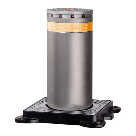
Flow Safe F70U Series Instruction manual

F70U SERIES
UNLOADER VALVE
INSTALLATION,
OPERATION, & MAINTENANCE MANUAL
Revision: E
Date of Issue: Jan. 31, 2022
Approved by: jwo GG
Engineering Projects Dir. Sr. Design Eng.

INSTALLATION, OPERATION, &
MAINTENANCE MANUAL
TITLE: F70U Series Rev. E
Unloader Valve Page 2 of 12
TABLE OF CONTENTS
Topic Page
1.0 General................................................................................................3
2.0 Description, Operation, Service Envelope, Installation, & Startup
2.1 Description / Operation........................................................................4
2.2 Service Envelope.................................................................................5
2.3 Installation............................................................................................5
2.4 Startup .................................................................................................6
3.0 Main Valve Maintenance
3.1 Disassembly of the F70U Series Main Valve.......................................6
3.2 Reassembly of the F70U Series Main Valve........................................9
4.0 Testing of the Main Valve Assembly....................................................10
5.0 Final Assembly Testing........................................................................10
6.0 Troubleshooting Guide.........................................................................11
7.0 Accessories
7.1 Softgoods Kits......................................................................................12
7.2 Internals Kits........................................................................................12
Illustrations
F70U Series, Main Valve 1-1/2x3 ……………….............................................7
F70U Series, Main Valve 2x3 and Larger ……………….................................8

INSTALLATION, OPERATION, &
MAINTENANCE MANUAL
TITLE: F70U Series Rev. E
Unloader Valve Page 3 of 12
1.0 GENERAL
1) This manual is intended to provide users with direction and guidance for the maintenance of
FLOW SAFE F70U Series valves. This manual indicates the proper method of valve
disassembly, soft goods replacement, and valve reassembly. FLOW SAFE provides this manual
as a guideline and reference only. It is not intended to serve as a training manual or
manufacturing guide. FLOW SAFE assumes no responsibility for personal or property damage
that may occur in conjunction with this manual.
2) FLOW SAFE recommends that all valves be placed on a regular maintenance schedule that
includes the routine replacement of softgoods. FLOW SAFE recommends softgoods
replacement every three years but cautions that each customer make their own determination
and set their own schedule based upon use and environment. FLOW SAFE believes that when
maintenance and reassembly is performed as outlined in this manual there is no safety hazard.
Cycling the valve at least once a year is considered to be good practice to verify operation.
3) When a new valve leaves FLOW SAFE, it has been manufactured and tested by trained and
experienced personnel. When you remove a valve from your system and perform the
maintenance tasks that are outlined herein you will need proper training.
Do not attempt to accomplish these tasks without adequate training and understanding of the
valve operation.
4) Any and all stated or implied warranties that are in effect during the purchase of a new FLOW
SAFE valve are null and void once the valve has been disassembled by someone other than
approved FLOW SAFE personnel.
5) It is highly recommended that all instructions herein be read in full prior to any assembly,
disassembly, or operation of this equipment.
6) The noted manufacturer’s standard lubricants should be used only if compatible with process fluid
and application.
7) Specific design details described in this document are subject to change without notice.
8) Should the need arise for general assistance, contact the FLOW SAFE Sales or Service
department at (716) 662-2585 or (800) 828-1036 in Orchard Park NY. For more detailed
technical assistance, contact the FLOW SAFE Engineering department at (716) 662-2585.

INSTALLATION, OPERATION, &
MAINTENANCE MANUAL
TITLE: F70U Series Rev. E
Unloader Valve Page 4 of 12
2.0 DESCRIPTION, OPERATION, SERVICE ENVELOPE, INSTALLATION, and STARTUP
2.1 DESCRIPTION / OPERATION
Typical valve assembly (3” x 4” size shown):
CLOSED OPEN
The FLOW SAFE F70U Series unloader valve provides a means to control flow for a variety of process
flow applications, such as compressor and blower unloading. It is designed to be repeatedly cycled at full
pressure throughout its range of rated temperatures.
System pressure is routed from below the valve through the pickup tube to the dome cavity above the
main piston. This dome pressure, acting on a differential area between the top and bottom of the piston,
creates a downward force on the seat to keep it closed.
Control valves in the dome tubing usually include an automatic (electric or pneumatic) valve to exhaust
dome pressure and thus open the main valve, and a manual valve to adjust the rate of dome loading
(pressurization) desired for the closing cycle.
The F70U uses an elastomeric O-ring as the main seat to achieve tight seating. A dynamic piston seal
guards against leakage from the dome cavity to the discharge. Wear rings on the piston help to provide
smooth and consistent operation, particularly for high-cycle conditions. Standard construction of the main
valve assembly includes threaded (in the 1-1/2 x 2 size) or ANSI/ASME Class 150 flanged connections
rated to 285 psig.
DOME
CAVITY
PICKUP
TUBE
INLET
OUTLET
FILTER
(OPTIONAL)
PISTON
ASSEMBLY
BODY
SOLENOID,
2-WAY SHOWN
(OPTIONAL)
SPEED
CONTROLLER
(OPTIONAL)
SEAT
DOME
EXHAUST
DOME
TUBE
INSTALLATION LOCATION
IF 3-WAY SOLENOID
INSTALLED (OPTIONAL)

INSTALLATION, OPERATION, &
MAINTENANCE MANUAL
TITLE: F70U Series Rev. E
Unloader Valve Page 5 of 12
2.2 SERVICE ENVELOPE
1Most common elastomers listed; contact Flow Safe for availability of other materials.
2.3 INSTALLATION
Prior to installation, check that the valve size and pressure rating meet system requirements. The F70U
unloader valve should be installed in accordance with accepted piping practices and, if applicable,
governing electrical codes. An upright orientation is preferred for maximum seal life.
F70U unloader valves may be furnished with dome tubing and control valves assembled at the factory,
based on customer specification. Guidelines in the next paragraphs should be followed if an F70U main
valve only has been provided for installation.
The exhaust path from the dome should be free from restrictions (additional valves, filters, etc.) for the
fastest main valve opening times. If a filter is used, it should be installed in the dome tube between the
main valve inlet and solenoid or tee fitting at the cap.
A 3-way solenoid valve should be installed as shown on Page 4, with its pressure port connected to the
dome tube, the cylinder port connected to the main valve dome (cap), and the exhaust port open or
connected to an appropriate discharge system.
If a 2-way solenoid valve is used to control dome pressurization, it must be installed on a separate branch
from the dome tube connection to the main valve cap, such as at the open end of a tee (see below).
For any electric or pneumatic control valve, a “normally closed” or “normally open” configuration should be
selected based on the control system used and the control valve manufacturer’s specifications.
SEAT MATERIAL 1PROCESS TEMP.,
o
F (°C)
UNLOADING PRESSURE,
psig (barg)
Min.
Max.
Min.
Max.
Buna
-
N
-30 (-34) 275 (135) 5 (.34) 285 (19.6)
Viton
®
-30 (-34) 400 (204) 5 (.34) 285 (19.6)
SOLENOID
(2
-
WAY SHOWN)
DOME TUBE
DOME
EXHAUST

INSTALLATION, OPERATION, &
MAINTENANCE MANUAL
TITLE: F70U Series Rev. E
Unloader Valve Page 6 of 12
2.4 STARTUP
Foreign particles or dirt can damage the valve and make it inoperative. Prior to installation, clean out the
piping thoroughly. If the valve is not installed immediately, inlet and outlet connections should be
protected and covered.
With the solenoid or pneumatic valve in its proper state to allow the main valve dome to pressurize, the
F70U assembly is ready for service and system pressure can be increased to the operating range.
Inspection and maintenance should be performed on a regular basis, typically once a year, depending on
the service conditions.
3.0 MAIN VALVE MAINTENANCE
3.1 DISASSEMBLY OF THE F70U SERIES MAIN VALVE
(See illustrations on Pages 7 and 8.)
CAUTION: Depressurize the system or safely block incoming line pressure before attempting
to disassemble or remove any valve from the installation.
1) Remove the control valve(s) and dome tube.
2) Remove the bolts and lockwashers that hold the cap in place.
3) With the cap removed, remove the top liner seal or gasket. Newer valves of the 1-1/2” x 2” size
have a press-in liner. In older 1-1/2 x 2’s, which do not have a liner, the piston seal and wear
rings bear directly against a machined bore within the body casting.
4) Carefully remove the piston assembly. Newer pistons may have an interior threaded hole into
which a cap bolt can be inserted to use for lifting. Note that the liner may come out with the
piston assembly. Care must be taken during this removal because any damage might result in an
eventual sealing problem when the valve is reassembled.
5) If the piston seal is in need of replacement, pry from underneath using a flat-blade screwdriver
and work the seal over the edge of its retaining lip at the top of the piston.
6) The liner may then be removed (except in 1-1/2 x 2 size); again, care must be taken not to
damage the liner. Do not attempt to pry or force the liner out as you may score the surface and
cause a sealing problem. Note that on valves 4” x 6” and larger, there is a second liner O-ring
seal in the main valve counterbore where the liner is supported.
7) To remove the seat, first remove the retainer screw. As the screw is held in the piston with the
aid of a locking Heli-Coil thread insert, considerable torque should be required to loosen it.
8) Remove the retainer plate and then the seat. If required, pry the retainer plate using the center
hole. Do not pry where the plate OD contacts the O-ring seat.
9) As required, install new main valve softgoods and reassemble valve per the instructions in
Section 3.2. Replacement parts are referenced in Section 7.0 of this manual.

INSTALLATION, OPERATION, &
MAINTENANCE MANUAL
TITLE: F70U Series Rev. E
Unloader Valve Page 7 of 12
F70U SERIES
MAIN VALVE, 1.5x2
ASSEMBLY ILLUSTRATION
BOLT/
LOCKWASHER
CAP
GASKET
LINER
(NEWER MODELS ONLY,
NOT REMOVABLE)
PISTON
SEAT
WEAR RINGS
(SLYDRINGS)
BODY
PICKUP TUBE
RETAINER
RETAINER SCREW,
LOCKING HELICOIL
PISTON SEAL
(TEFLON V-SEAL
w/ SS SPRING)
DOME FEED
PORT
DRAIN PLUG

INSTALLATION, OPERATION, &
MAINTENANCE MANUAL
TITLE: F70U Series Rev. E
Unloader Valve Page 8 of 12
F70U SERIES
MAIN VALVE, 2x3 AND LARGER
ASSEMBLY ILLUSTRATION
BOLT/
LOCKWASHER
CAP
LINER SEAL(S)
(LOWER SEAL
ON 4X6 &
LARGER ONLY)
LINER
PISTON
SEAT
WEAR RINGS
(SLYDRINGS)
BODY
PICKUP TUBE
RETAINER
RETAINER
SCREW / BOLT,
LOCKING HELICOIL
PISTON SEAL
(TEFLON V-SEAL
w/ SS SPRING,
EXCEPT O-RING
ON 12x16
DOME FEED
PORT
LIFT BRACKET
DRAIN PLUG

INSTALLATION, OPERATION, &
MAINTENANCE MANUAL
TITLE: F70U Series Rev. E
Unloader Valve Page 9 of 12
3.2 REASSEMBLY OF THE F70U SERIES MAIN VALVE
(See illustrations on Pages 7 and 8.)
1) Prepare new softgoods for installation. Take care in handling of all seats, seals, gaskets, and
metal sealing surfaces. All parts should be clean and free of any debris or contaminants.
2) Reinstall the liner (except 1-1/2 x 2) and liner seal(s) into the body. Do not nick or excessively
stretch the liner seal O-rings. The bottom O-ring (for 4 x 6 and larger) may be carefully set in its
sealing area in the body before the liner is inserted, or it may be fitted onto the liner and, if
necessary, held in place with a suitable lubricant (e.g., Dow Corning 33 or Molykote). For 2 x 3
and larger valves, the top liner seal should be lightly pressed into place in its groove, such that it
is evenly spread around the liner circumference and will not be pinched when reinstalling the
valve cap. For the 1-1/2 x 2 size, position the gasket on top of the body.
3) Insert the seat into the bottom of the piston, using care to position the seat completely within the
groove. Ensure that there are no scratches, gouges, or particles on the seat, and that it is not
twisted. Carefully position the retainer plate over the seat.
4) Apply Vibra-tite or Loctite to the retainer screw threads. Insert the screw(s) into the piston and
tighten firmly, as follows: Retainer
Valve size screw size Torque
1-1/2x2, 2x3, 3x4 1/4-20UNC 80 – 90 in-lbs
4x6, 6x8, 8x10 1/2-20UNF 30 – 35 ft-lbs
12x16 3/8-24UNF 12 – 15 ft-lbs
IMPORTANT: Retainer screw must meet firm resistance against locking Heli-Coil in
piston, and require a wrench to completely install. Replace Heli-Coil if worn or damaged.
5) For all sizes except 12 x 16, install the Teflon piston seal by pressing it evenly over the beveled
retaining lip at the top of the piston. For the 12 x 16, lightly lubricate the O-ring piston seal with
Dow Corning 33 or equivalent and fit into its groove.
6) Fit the wear rings in their grooves around the piston assembly. While holding the wear rings
(especially the free ends) in place, carefully lower the piston assembly into the liner. The piston
should move freely up and down, with some resistance from the seal and wear rings. It is
critically important that this installation result in even seating of the soft seat onto the machined
nozzle surface in the valve body.
7) After checking placement of the top liner seal or gasket [See Step (2)], as applicable, the cap may
then be positioned on top of the body.
8) The cap bolts, with washers, can then be reinserted. Apply anti-seize compound to bolt threads.
The following torque values are recommended:
Valve Size Cap Bolt Size Torque (ft-lbs)
1-1/2x2 1/4-20UNC 8 - 10
2x3, 3x4 1/2-13UNC 55 - 60
4x6 1/2-20UNF 55 - 60
6x8 5/8-18UNF 80 - 90
8x10, 12x16 3/4-16UNF 150 - 160
9) The main valve is now assembled. It should be tested per Section 4.0 before reinstalling control
valve(s) and dome tube, at which time tests described in Section 5.0 should be performed prior to
return to service.

INSTALLATION, OPERATION, &
MAINTENANCE MANUAL
TITLE: F70U Series Rev. E
Unloader Valve Page 10 of 12
4.0 TESTING OF THE MAIN VALVE ASSEMBLY
When main valve has been reassembled, it should be tested for leakage and piston lift on a test stand
according to the following. Refer to the figures on Pages 7 and 8.
1) Connect a pressure source to the dome feed port. Plug any openings in the outlet area, such as
the drain.
2) To test the piston seal and liner seal(s) or gasket, pressurize the dome with at least 5 psig (and
not greater than 285 psig) of air.
3) With a bubble tester or wet paper towel over the outlet, verify that there is no leakage. Also verify
no leakage around the cap and cap bolts by spraying the area thoroughly with soapy water and
checking for bubble formation.
4) To test the main valve seat, block off the pickup tube opening in the body by inserting a pipe plug.
CAUTION: Pressurizing the inlet to a higher value than dome pressure may cause the
main piston to open.
Repressurize the dome as in (2), and introduce pressure at the inlet up to the value of dome
pressure. Check for leakage at the main valve outlet.
5) With the dome feed port open, pressurize the inlet up to approximately 5 psig. The piston should
open slightly, allowing air to discharge through the outlet of the valve.
6) To check for full piston lift, install a blind flange on the valve outlet. Again pressurize the inlet up
to 5 psig. The piston should fully lift and hit the bottom of the cap, as indicated by sound or a rod
placed through the dome feed port. If this test is not feasible, attempt to confirm free piston travel
by reaching in the main valve outlet and manually lifting the piston.
7) If leakage is noted past any seal or seat, disassemble the valve and examine the parts for
contamination or damage, or refer to the troubleshooting guide in Section 6.0.
8) Proceed to the next section for testing of the complete valve assembly.
5.0 FINAL ASSEMBLY TESTING
1) Reinstall dome tube and any control valves.
2) With the solenoid or pneumatic valve connected to the normal power or air supply, verify that it
operates according to its “normally closed” or “normally open” configuration. Leave this valve in
its normal position for system operation, to enable the main valve dome to pressurize.
3) Ensure that the manual valve (speed controller) is open.
4) Verify that main piston is down in the seated position.
5) Pressurize the main valve inlet to approx. 10 psig.
6) Verify that the main piston remains closed and is leak-tight.
7) Actuate the solenoid or pneumatic valve and verify that dome exhausts and main piston opens.
8) Restore the solenoid or pneumatic valve to its normal position and verify that dome repressurizes
and the main piston closes.
9) Adjust the manual valve (speed controller), if desired, to change the rate of dome
repressurization. Repeat Steps (5) through (8).

INSTALLATION, OPERATION, &
MAINTENANCE MANUAL
TITLE: F70U Series Rev. E
Unloader Valve Page 11 of 12
6.0 TROUBLESHOOTING GUIDE
Symptom
Possible Cause
Remedy
The main valve leaks
around the cap or cap
bolts.
Cap bolt(s) loose, or insufficient /
uneven bolt torque. Retighten the cap bolts per Section
3.2.
Sealing surface on cap is
damaged. Repair defect or replace cap.
Upper liner seal or gasket is
damaged or contaminated. If damaged, replace with new seal(s).
If
contaminated, clean and reinstall.
Air trapped in cap bolt hole(s). Wait until leakage stops (applicable to
very recent cap reinstallation only).
The main valve leaks
through the outlet. Damage to, or contamination on:
piston seat or main valve nozzle,
piston seal / sealing surface, or
lower liner seal / sealing surface.
Disassemble the valve, remove the
piston and liner, and examine the seat,
seals, and sealing surfaces under
magnification. If damaged, replace
with new part(s); if contaminated, clean
and reinstall.
The main valve does
not close. Dome tube, pickup tube, or filter
damaged or plugged. Clean / unplug, or replace if damaged.
Pickup tube is oriented
incorrectly. Ensure intake port in tube is facing
upstream (toward flow to the inlet).
Control valve(s) not functioning
properly. Check valves for proper position,
orientation, and control connections.
Piston seal is leaking. Perform test described in Section 4.0,
Steps (1) – (3).
Contamination between liner and
piston. Disassemble valve. Clean surfaces;
remove any burrs/gouges if possible or
replace damaged parts.
Outlet piping is obstructed or too
small. Check outlet piping for obstructions.
Pipe size should be at least the
nominal size of the valve outlet.
The main valve does
not open. Dome pressure exhaust path
blocked. Check control valve(s) for proper
operation; clear exhaust path of any
blockage.
Piston seized. Check piston and liner surfaces and
wear rings for contamination or
damage. Clean or replace parts as
necessary.
Inlet or outlet blocked. Clear blockage in a safe manner.

INSTALLATION, OPERATION, &
MAINTENANCE MANUAL
TITLE: F70U Series Rev. E
Unloader Valve Page 12 of 12
7.0 ACCESSORIES
7.1 SOFTGOODS KITS
Valve Size Softgoods Kit
Part Number
1-1/2 x 2
2 x 3
3 x 4
4 x 6
6 x 8
8 x 10
12 x 16
UN-15X02-7XY
UN-02X03-7XY
UN-03X04-7XY
UN-04X06-7XY
UN-06X08-7XY
UN-08X10-7XY
UN
-
12X16
-
7
XY
Most common elastomers listed;
contact Flow Safe for availability of other materials.
Softgoods Kit contents
(See illustrations on Pages 7 & 8) Qty.
Seat 1
Wear ring 2
Liner seal (2 x 3, 3 x 4) 1
(4 x 6 and up) 2
Gasket (1-1/2 x 2 only) 1
Piston seal 1 Teflon with stainless steel spring except 12x16
7.2 INTERNALS KITS
Applicable to most common F70U sizes; contact factory for other replacement parts.
Kit P/N
1-1/2 x 2 F70U-15X02-KIT (previously 02-3003)
2 x 3 F70U-2X3-KIT (previously 02-3001)
3 x 4 F70U-3X4-KIT (previously 02-3002)
Internals Kit contents
(See illustrations on Pages 7 & 8) Qty.
Piston 1
Retainer 1
Retainer screw 1
Liner (except 1-1/2 x 2) 1
X = Seat Material
Y = Liner Seal / Gasket Material
Code
B
V
E
Z
C
N
Buna-N
Viton ®
EPR / EPDM
Kalrez ®
Chemraz ®
Lo-temp nitrile
Table of contents
Other Flow Safe Control Unit manuals
Flow Safe
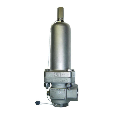
Flow Safe F7000 SERIES Instruction manual
Flow Safe
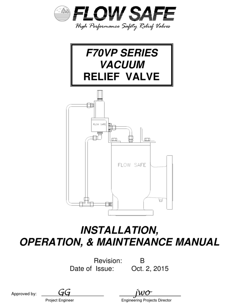
Flow Safe F88 Series Instruction manual
Flow Safe
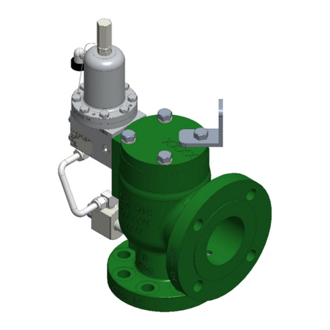
Flow Safe F70VP Series Instruction manual
Flow Safe
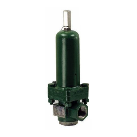
Flow Safe F8000 Series Owner's manual
Flow Safe
Flow Safe F84L Series Instruction manual
Flow Safe
Flow Safe F84L Series Instruction Manual
Flow Safe
Flow Safe F88 Series Instruction manual
