KONVEKTA FR4 Guide

Konvekta AG
Konvekta AGKonvekta AG
Konvekta AG
Am Nordbahnhof 5
34613 Schwalmstadt
Germany
+49 0 ) 66 91 / 76 – 0
+49 0 ) 66 91 / 76 - 200
www.konvekta.com
Instructions for install
Instructions for installInstructions for install
Instructions for installa
aa
ation and
tion and tion and
tion and
se
sese
ser
rr
rvice
vicevice
vice
for control unit
for control unitfor control unit
for control unit
FR4
FR4FR4
FR4
12
12 12
12 -
--
- 24 Volt DC
24 Volt DC 24 Volt DC
24 Volt DC
ID#: 110013962AA
ID#: 110013962AAID#: 110013962AA
ID#: 110013962AA-
--
-a02
a02a02
a02
Valid from 08
Valid from 08Valid from 08
Valid from 08/200
/200/200
/2008
88
8

110013961AA
date of change: 18.08.2008
page: 2/19
Contents
ContentsContents
Contents
page
1
11
1
Technical data
Technical dataTechnical data
Technical data of control unit
of control unit of control unit
of control unit ................................
................................................................
................................................................
................................................................
................................................................
................................................................
.......................................................
..............................................
....................... 3
33
3
2
22
2
General description of the control unit
General description of the control unitGeneral description of the control unit
General description of the control unit................................
................................................................
................................................................
................................................................
................................................................
................................................................
.......................................
..............
....... 4
44
4
2.1
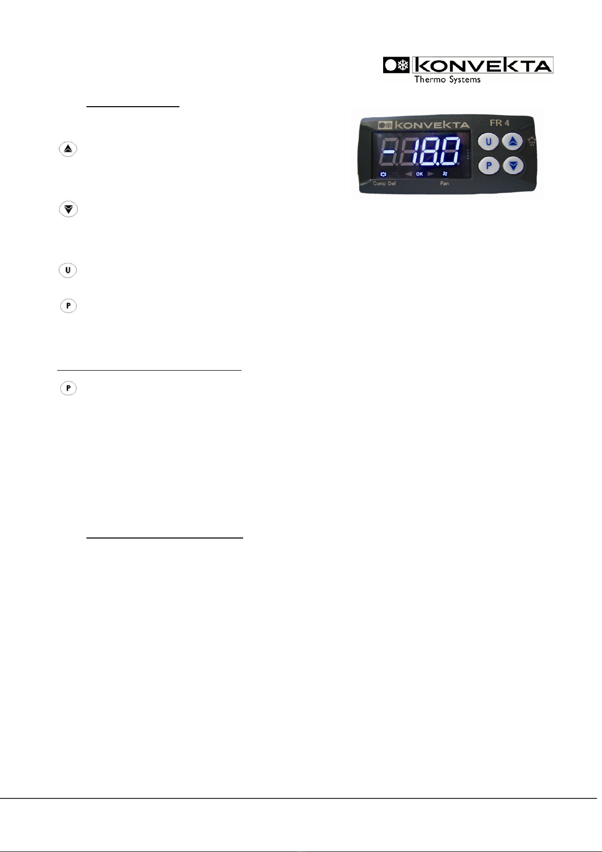
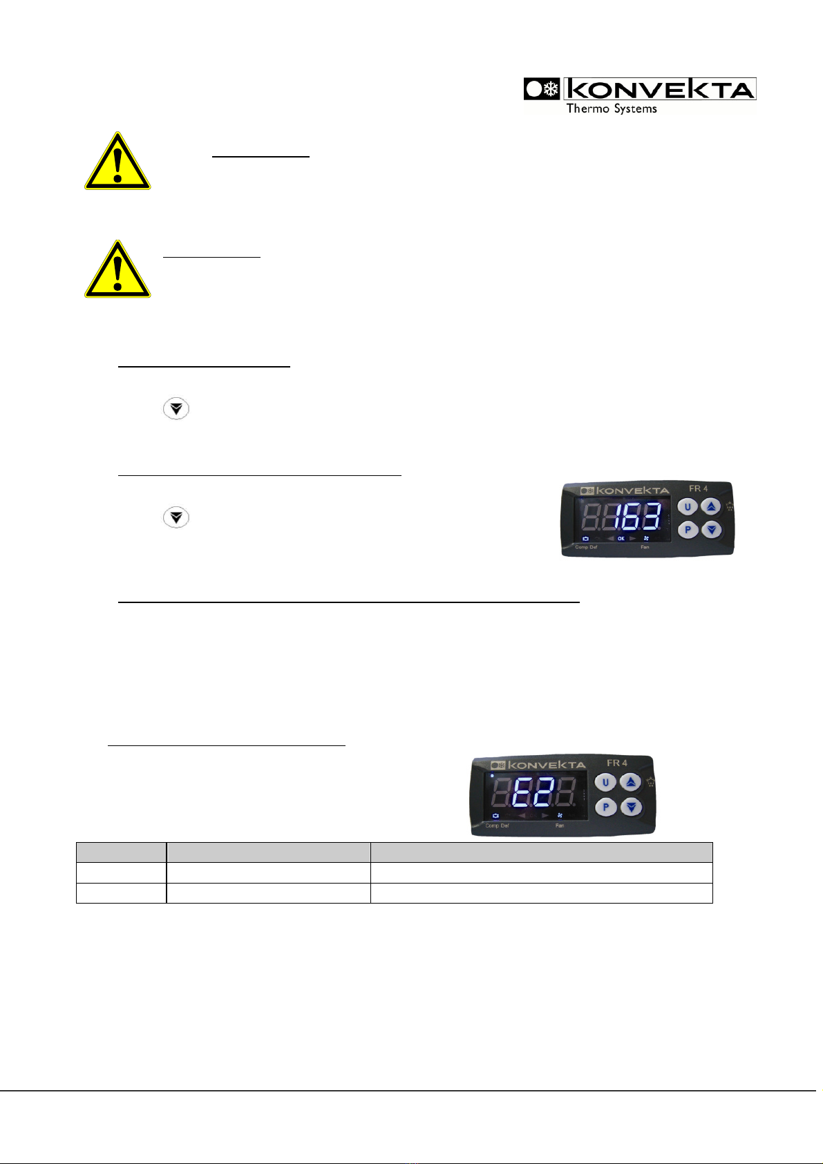
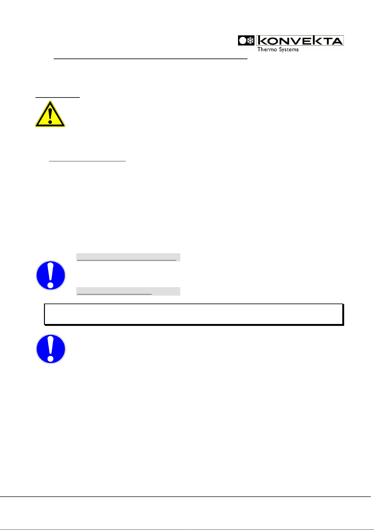
LED-display ...............................................................................................................................................................4
2.2
Programming Menu.................................................................................................................................................4
2.3
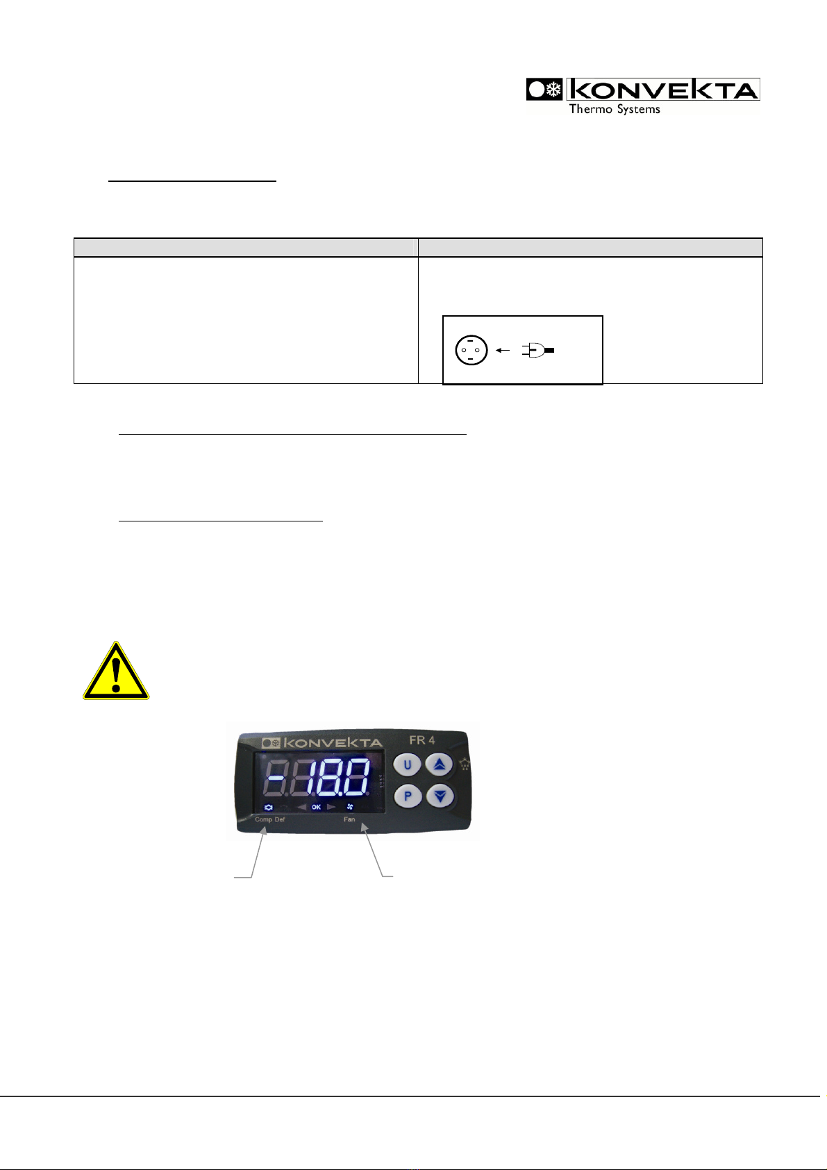
Connecting and Safety instructions.....................................................................................................................5
2.4
Functions of buttons...............................................................................................................................................6
2.5
Factory setting / delivery state FR4.....................................................................................................................6
3
33
3
Switching
SwitchingSwitching
Switching-
--
-on the unit
on the uniton the unit
on the unit ................................
................................................................
................................................................
................................................................
................................................................
................................................................
................................................................
................................................................
......................................
............
...... 7
77
7
3.1
Switching-on the refrigeration unit by button [U] of FR4.............................................................................7
3.2
Indication and change of setpoint........................................................................................................................7
3.3
Sampling of operating hours .................................................................................................................................8
3.4
Sampling of operating hours since last service ................................................................................................8
3.5
Sampling of the temperature values of room sensor and evaporator sensor..........................................8
4
44
4
Faults
FaultsFaults
Faults
–
––
–
indications and signals
indications and signalsindications and signals
indications and signals ................................
................................................................
................................................................
................................................................
................................................................
................................................................
......................................................
............................................
...................... 8
88
8
5
55
5
Adjustment of
Adjustment of Adjustment of
Adjustment of P
PP
Parameters in the
arameters in the arameters in the
arameters in the m
mm
men
enen
enu
uu
u................................
................................................................
................................................................
................................................................
................................................................
................................................................
.......................................
..............
....... 9
99
9
5.1
Example for change of a parameter, here parameter defrost interval “di nt”..........................................9
5.2
Conversion to cooling with recirculated air defrosting / or replace a FR1, FR2 or FR3.......................9
5.3
Conversion to cooling – heating with hotgas – defrosting with hotgas.................................................. 10
6
66
6
Control of defrosting
Control of defrostingControl of defrosting
Control of defrosting................................
................................................................
................................................................
................................................................
................................................................
................................................................
................................................................
................................................................
....................................
........
.... 10
1010
10
7
77
7
Configuration of the parameters with “FR 4
Configuration of the parameters with “FR 4 Configuration of the parameters with “FR 4
Configuration of the parameters with “FR 4 c
cc
copy
opyopy
opy-
--
-k
kk
key”
ey”ey”
ey” ................................
................................................................
................................................................
................................................................
.........................................
..................
......... 11
1111
11
8
88
8
Logi
LogiLogi
Logic
cc
c >>
>> >>
>> Explanations for the functions of the control conditions
Explanations for the functions of the control conditionsExplanations for the functions of the control conditions
Explanations for the functions of the control conditions................................
................................................................
.......................................................
..............................................
....................... 12
1212
12
8.1
Cooling and defrosting with hot gas >> delivery state FR4 ............................................................... 12
8.2
Cooling and defrosting with recirculated air >> see changes in parameters point 5.2....................... 12
8.3
Neutral zone cooling + heating with hot gas) and defrosting with hot gas >> see changes in
parameters point 5.3. .......................................................................................................................................... 12
9
99
9
Connection diag
Connection diagConnection diag
Connection diagram
ramram
ram
a
aa
and
nd nd
nd p
pp
parameter
arameterarameter
arameter chart
chart chart
chart ................................
................................................................
................................................................
................................................................
................................................................
................................................................
................................ 13
1313
13
9.1
Connection diagram ............................................................................................................................................ 13
9.2
Parameter chart.................................................................................................................................................... 13

110013961AA
date of change: 18.08.2008
page: 3/19
1
11
1Technical data
Technical dataTechnical data
Technical data of control unit
of control unit of control unit
of control unit
Type / operating voltage
Type / operating voltageType / operating voltage
Type / operating voltage:
::
:
KONVEKTA
KONVEKTA KONVEKTA
KONVEKTA part no.
part no.part no.
part no.:
::
:
FR4 / 12 – 24 V H11-001-396
Housing
HousingHousing
Housing:
::
:.................................................................. UL 94 V0 plastic material
Dimensions
DimensionsDimensions
Dimensions:
::
:........................................................... frontal: 78x35 mm; depth: 64 mm
Mounting
MountingMounting
Mounting:
::
: ............................................................... panel mounting in a 29x71 mm panel cut-out
Frontal protection
Frontal protectionFrontal protection
Frontal protection:
::
:............................................... IP65 with sealing
Connections
ConnectionsConnections
Connections:
::
: ......................................................... Screw terminal block
≤
2,5mm
2
wiring
Power supply
Power supplyPower supply
Power supply:
::
:
................................
................................................................
.......................................
..............
.......
12 – 24 V AC/DC, -10%, +10%
Power consumption
Power consumptionPower consumption
Power consumption:
::
: ........................................... 3 VA max.
Display
DisplayDisplay
Display:
::
: ................................................................... 4-digit, blue LED, height 12mm
Inputs
InputsInputs
Inputs:
::
:
................................................................ 2 x PTC-sensor
Rela
RelaRela
Relay outputs
y outputsy outputs
y outputs:
::
:
c
cc
compre
ompreompre
ompressor:
ssor:ssor:
ssor: ................................................. Relay NOC normally open contact) 16 A
defrost
defrostdefrost
defrost:
::
: ....................................................... Relay change-over contact 8 A
fans
fansfans
fans:
::
: .......................................................... Relay NOC normally open contact) 5 A
D
DD
Data storage
ata storageata storage
ata storage.......................................................... non-volatile memory EEPROM)
Operating
Operating Operating
Operating temperatur
temperaturtemperatur
temperature
ee
e:
::
: ..................................... 0..50°C
Storage t
Storage tStorage t
Storage temperatur
emperaturemperatur
emperature
ee
e:
::
: .......................................... -10..60°C
H
HH
Humidity
umidityumidity
umidity:
::
:................................
................................................................
.............................................................
..........................................................
............................. 10 to 95% without condensation)
Measuring range sensor
Measuring range sensorMeasuring range sensor
Measuring range sensor PTC NTC):
PTC NTC): PTC NTC):
PTC NTC): ............. -50 to 150°C -50 to 109°C)
Resolution
ResolutionResolution
Resolution:
::
:............................................................. 1°C or 1°F
Accuracy
AccuracyAccuracy
Accuracy:
::
:................................................................ ±0,5%

110013961AA
date of change: 18.08.2008
page: 4/19
2
22
2General description of the control unit
General description of the control unitGeneral description of the control unit
General description of the control unit
Model FR4
FR4FR4
FR4 is an electronical control unit 78x35mm) suitable for applications on medium or low tempera-
ture refrigeration units, which has three relay outputs to control compressor, defrost and evaporator
blower as well as two PTC-/NTC-sensor-inputs in order to measure the room temperature and evapora-
tor temperature. Defrosting can be recirculation air as well as hot-gas defrosting. The blower can be acti-
vated during defrosting upon request. The sensor is suitable for refrigeration. The control unit FR4 is suit-
able for refrigeration as well as heating applications only hot-gas heating). Supply voltage may be between
10 and 28V.
The following functions can be adjusted:
•room temperature „only refrigeration“ or „refrigeration and heating with hot gas “)
•automatic defrosting hot gas or recirculating air)
•manual defrosting hot gas or recirculating air)
⇒Faults are shown in the display via flashing indication see point 4).
This present instructions for installation and service is amended by the „operating
instructions for refrigeration units“, KONVEKTA no: BBA-FR4-2AA.
2.1 LED-display
The display shows information about the current control mode via different LED.
The functions are listed as follows:
LED
LEDLED
LED
STATUS
STATUSSTATUS
STATUS
FUN
FUNFUN
FUNCT
CTCT
CTION
IONION
ION
Comp
illuminated compressor is active
Comp
blinking minimum off-duration of compressor is active
Fan illuminated Blowers active
Def
illuminated defrosting active
Def
blinking Manual defrosting active
OK illuminated function OK, no fault active
2.2 Programming Menu
The programming menu includes all parameters of the unit
Service
Service Service
Service level
levellevel
level!).
!). !).
!). For this level you need a
password
, see example in point 5.1.

110013961AA
date of change: 18.08.2008
page: 5/19
2.3 Connecting and Safety instructions
-
--
-
Please read before connecting
Please read before connectingPlease read before connecting
Please read before connecting!
! !
! -
--
-
•For safety reasons the control unit FR4
FR4 FR4
FR4 shall not be used for applications different from those described
in this manual.
•Before use please check the limits of this control unit as well as its applications.
Safety instructions
Safety instructionsSafety instructions
Safety instructions
Before connecting the unit please check wether the supply voltage is correct. Please pay attention to the
prescribed ambient conditions respectively their humidity and temperature limits. Should these conditions
not be followed, malfunctions can not be excluded.
Attention
AttentionAttention
Attention:
::
:
Before switching-on the unit, please check once again correct connection.
Never run this unit without housing.
Please install the sensor where it is not accessible for the end customer
Please consider the maximum current which can be applied to each relay see technical data / point 1).
Please ensure that all sensors are installed with enough distance to under-voltage cables. By this, distorted
temperature measurements can be avoided and the unit is protected from voltage interspersion by the
sensor-inputs.
Installation
Installation Installation
Installation a
aa
and
nd nd
nd mounting
mountingmounting
mounting
The control unit FR4
FR4FR4
FR4 shall be mounted on panel in a 71x29 mm
71x29 mm71x29 mm
71x29 mm hole and fixed by the fastening frame.
For a faultless operation the ambient temperature should be between 0 und 50 °C. Please avoid intense
vibration, aggressive gases, high fouling or humidity.
You have to care for enough air circulation at the air slots.
Ele
EleEle
Elec
cc
ctr
trtr
trical
icalical
ical
co
coco
connections
nnectionsnnections
nnections
The control unit FR4
FR4FR4
FR4 is provided with screw terminals for a wire diameter of
≤
2,5mm
2
. Before voltage
supply is connected please make sure that the auxiliary energy complies with the instrument’s require-
ments. Please ensure that the inlet cables are installed with enough distance to under-voltage cables.
Do not exceed the maximum voltage allowed on each relay.
Sensor
SensorSensor
Sensor
connections
connectionsconnections
connections
The sensor peak should be mounted upwards in order to avoid accumulation of liquids or condense wa-
ter. We recommend to place the thermostat away from air flow in order to have a correct measurement
of the average room temperature.
These instructions contain all necessary information for installation of the control unit. In case you need
further information respectively explanation our technical after-sales service will be at your disposal
In the course of further developments we reserve the right to technical modifications without prenotice.
Guarantee and liability conditions of Konvekta AG’s general business conditions are not enlarged by the
above notes. Indications and photos should neither be copied and circulated nor used for competitor’s
purposes. All rights according to the copyright remain expressly reserved.
Manufacturer: KONVEKTA AG,
KONVEKTA AG, KONVEKTA AG,
KONVEKTA AG, P.O. Box
P.O. BoxP.O. Box
P.O. Box 2280, 34607 Schwalmstadt
2280, 34607 Schwalmstadt 2280, 34607 Schwalmstadt
2280, 34607 Schwalmstadt, Germany
, Germany, Germany
, Germany

110013961AA
date of change: 18.08.2008
page: 6/19
2.4 Functions of buttons
The control unit FR4
FR4FR4
FR4
has four buttons:
[UP] - Scrolls through the positions of
the menu
- raises the values
- switching-on of manual defrosting
[DOWN] - Scrolls through the positions of the menu
- lowers the values
- sampling of operating-hour counter
- sampling of service-hour counter
[U] - ON / OFF button
- sampling of temperatures at room sensor and evaporator sensor PR1 – PR2)
[P] - access to setpoint
- access to menus
- confirmation of commands
Setting of temperature setpoint
Setting of temperature setpointSetting of temperature setpoint
Setting of temperature setpoint:
::
:
Indication of temperature
Indication of temperature Indication of temperature
Indication of temperature setpoint
setpointsetpoint
setpoint
Press button [P]. The display shows alternately „SP 1” and the current adjusted setpoint.
Change of the setpoint
Change of the setpointChange of the setpoint
Change of the setpoint:
::
:
To change the setpoint you have to press button [UP] or [DOWN] within 15 seconds until
the desired setpoint is indicated. Confirm with [P].
A
AA
Attention
ttentionttention
ttention:
: :
:
The new value will be automatically adopted and stored if it is not confirmed within 15 sec-
onds.
2.5 Factory setting / delivery state FR4
Delivery state/factory setting of control unit FR4 will be as follows:
Refrigeration with hot-gas defrosting! see point 7.1. on page 11)
Refer to the Konvekta set values in column „Def.” from the enclosed parameter list see point 8
page 12 to 18)!

110013961AA
date of change: 18.08.2008
page: 7/19
3
33
3Switching
SwitchingSwitching
Switching-
--
-on the unit
on the uniton the unit
on the unit
Analog to operating instructions no. BBA-FR4-1AA)
3.1 Switching-on the refrigeration unit by button [U] of FR4
Press button [U] for 3 seconds. The display shows “PR2” blinking; afterwards the current room tempera-
ture will be indicated.
3.2 Indication and change of setpoint
Press button [P] once, alternately blinking appear „SP1“ >> setpoint.
Now you can change the setpoint using the arrow keys -30 to +30°C)
Now press button [P] once and the new value will be stored.
A
AA
Attention
ttentionttention
ttention:
: :
:
The new value will be automatically adopted and stored if it is not confirmed within 15 sec-
onds.
In refrigeration operation the room temperature is indicated, LED’s for compressor „Comp“ and fans
„Fan“ are illuminated.
Drive operation
Drive operationDrive operation
Drive operation
Stand
StandStand
Stand-
--
-by operation
by operationby operation
by operation
•start vehicle engine
see original operating instructions of the vehi-
cle)
•For units with additional stand-by operation
230V/400V) you only have to plug in the power
plug for stand-by refrigeration.
compressor ON
evaporator/condensor
-
blower activ
e
Mains operation:
Plug in power plug

110013961AA
date of change: 18.08.2008
page: 8/19
ATTENTION
ATTENTIONATTENTION
ATTENTION:
::
:
The factory setpoint is
The factory setpoint is The factory setpoint is
The factory setpoint is 1°C.
1°C.1°C.
1°C.
This setpoint has to be adapted to the storage
This setpoint has to be adapted to the storage This setpoint has to be adapted to the storage
This setpoint has to be adapted to the storage temperatur
temperaturtemperatur
temperature of the transport
e of the transport e of the transport
e of the transport
goods
goodsgoods
goods!
!!
!
ATTENTION
ATTENTIONATTENTION
ATTENTION:
::
:
The factory minimal setpoint
The factory minimal setpointThe factory minimal setpoint
The factory minimal setpoint „SPLL
„SPLL „SPLL
„SPLL”
””
”
is adjusted to
is adjusted to is adjusted to
is adjusted to -
--
-30°C.
30°C.30°C.
30°C.
In case of use as a
In case of use as a In case of use as a
In case of use as a chill
chillchill
chilling unit the p
ing unit the ping unit the p
ing unit the parameter „SPLL
arameter „SPLLarameter „SPLL
arameter „SPLL”
””
”
has to be adjusted to
has to be adjusted to has to be adjusted to
has to be adjusted to 0!
0!0!
0!
3.3 Sampling of operating hours
Switch-on control unit FR4 with button [U].
Press button once. Now the total operating hours of the refrigeration unit will be indicated for
approx. 5 seconds.
3.4 Sampling of operating hours since last service
Switch-on control unit FR4 with button [U].
Press button twice. Now the operating hours of the refrigeration unit
since the last service are indicated for approx. 5 seconds.
3.5 Sampling of the temperature values of room sensor and evaporator sensor
Press button [U] once; the display shows alternately blinking „PR 2” and the measured evaporator tem-
perature. By pressing button [U] once again, „PR 1” is indicated in the display alternately blinking with the
measured room temperature.
After 15 seconds the display switches back to the current room temperature.
4
44
4Faults
FaultsFaults
Faults
–
––
–
indications and signals
indications and signalsindications and signals
indications and signals
The display shows faults by blinking indication.
If there is a fault, no control is possible!
Indication
IndicationIndication
Indication
Description
DescriptionDescription
Description
Fault s
Fault sFault s
Fault source
ourceource
ource
”E1” Fault with room sensor Cable rupture or sensor short-circuit
”E2” fault with evaporator sensor Cable rupture or sensor short-circuit

110013961AA
date of change: 18.08.2008
page: 9/19
5
55
5Adjustment of
Adjustment of Adjustment of
Adjustment of P
PP
Parameters in the
arameters in the arameters in the
arameters in the m
mm
men
enen
enu
uu
u
The single parameters are classified in groups:
a) Group
]
SP parameter concerning set point)
b) Group
]
InP parameter concerning measuring inlets)
c) Group
]
reG parameter concerning temperature control)
d) Group
]
dEF parameter concerning defrost process)
e) Group
]
FAn parameter concerning fans/blowers)
f) Group
]
PrC parameter concerning switch-on delay / evaporator protection)
You will find the explanations to the single parameters in point 8
88
8 from page 13
13 13
13.
..
.
Access to menu is secured by a password
Access to menu is secured by a passwordAccess to menu is secured by a password
Access to menu is secured by a password!
!!
!
5.1 Example for change of a parameter, here parameter defrost interval “di nt”
For selecting the menu please press and hold button [P]. “SP 1” is blinking in the display. After 5 seconds a „0“
appears. By pressing buttons
and
the password „213
213213
213“ is set. Now press button [P] once, in order to
confirm the password.
The display now shows the term of the first group „
]
SP“. By pressing buttons
and
the other groups
can be selected, by pressing button [P] the respective group is opened.
In order to change the defrosting intervals please browse with buttons
and
, until group „
]
dEF“
appears in the display. By pressing button [P] you open this group. First the display shows parameter „dtyP“
blinking. By pressing buttons
and
you can choose paramenter „di nt“; parameter „di nt“ is now blink-
ing in the display. By pressing button [P] once, the current setting is shown, “di nt” and the adjusted value
“1,30” are blinking alternately. Now the value can be changed. The new value is stored by leaving the pa-
rameter. You can leave the parameter with button
. If you press button
longer, the menu switches
back to the groups, afterwards you can leave the menu by pressing this button longer once again.
5.2 Conversion to cooling with recirculated air defrosting / or replace a FR1, FR2 or FR3
Contrary to the factory setting „cooling with hot-gas defrosting”, the following parameters have to be
changed:
-parameter „dtyP“ in group „
]
dEF“ has to be changed from „in“ to „FdE“
-parameter „tdCO“ in group „
]
dEF“ has to be changed from „1“ to „off“
-parameter „Fd“ in group „
]
FAn“ has to be changed from „1“ to „off“
-If no evaporator sensor has been installed e.g. replace
replacereplace
replace FR1
FR1 FR1
FR1) the parameter „PR 2“ in group
„
]
InP“ has to be changed from „on“ to „off“
If you replace a FR1, FR2 or FR3 with the FR4 and the external ON-OFF-button should be used further-
more or further instruments such as temperature recorder or heating should be switched on together with
the FR4 by an external button, you have to
-change parameter „Usrb“ in group „
]
Pan“ from „4“ to „OFF“.

110013961AA
date of change: 18.08.2008
page: 10/19
5.3 Conversion to cooling – heating with hotgas – defrosting with hotgas
Contrary to the factory setting, the following parameter has to be changed:
-parameter „FunC“ in group „
]
rEG“ has to be changed from „CooL“ to „nr“.
ATTENTION:
ATTENTION:ATTENTION:
ATTENTION:
Parameter
ParameterParameter
Parameter „FunC“
„FunC“ „FunC“
„FunC“ should only be changed from
should only be changed from should only be changed from
should only be changed from „CooL“
„CooL“ „CooL“
„CooL“ to
toto
to „nr“
„nr“ „nr“
„nr“ if a fluid e
if a fluid e if a fluid e
if a fluid ex-
x-x-
x-
tr
trtr
tractor is i
actor is iactor is i
actor is in
nn
nstalled in the suction pipe of the refri
stalled in the suction pipe of the refristalled in the suction pipe of the refri
stalled in the suction pipe of the refrig
gg
geration unit
eration uniteration unit
eration unit!
!!
!
Otherwise risk of damages to compressor.
Otherwise risk of damages to compressor.Otherwise risk of damages to compressor.
Otherwise risk of damages to compressor.
6
66
6Control of defrosting
Control of defrostingControl of defrosting
Control of defrosting
Factory setting of control unit FR4 is hot-gas defrosting. In case of use in refrigeration units with recircu-
lated air defrosting the following parameters have to be changed:
-parameter „dtyP“ in group „
]
dEF“ has to be changed from „in“ to „FdE“
-parameter „tdCO“ in group „
]
dEF“ has to be changed from „1“ to „off“
-parameter „Fd“ in group „
]
FAn“ has to be changed from „1“ to „off“
-If no evaporator sensor has been installed e.g. replace FR1
replace FR1replace FR1
replace FR1) the parameter „PR 2“ in group
„
]
InP“ has to be changed from „on“ to „off“
The preadjusted maximum defrosting duration is 15 minutes.
During defrosting process „dEF” is indicated and the LEDs „Def” and „Comp”
are illuminated.
After the end of defrosting there is 1 minute drip-off time. Display shows „PdEF“.
The LEDs „Comp” and „Fan” are blinking.
Recommended defrosting inte
Recommended defrosting inteRecommended defrosting inte
Recommended defrosting inter
rr
rvals:
vals:vals:
vals:
Fresh meat and cheese: 1:00 hours
Dairy product: 2:00 hours
Deep freezing products: 3:00 hours
Pre
PrePre
Pre-
--
-adjustment:
adjustment:adjustment:
adjustment:
1:30
1:30 1:30
1:30 hours
hourshours
hours

110013961AA
date of change: 18.08.2008
page: 11/19
7
77
7Configuration of the parameters with “FR 4
Configuration of the parameters with “FR 4 Configuration of the parameters with “FR 4
Configuration of the parameters with “FR 4 c
cc
copy
opyopy
opy-
--
-k
kk
key”
ey”ey”
ey”
FR4 copy-key: Konvekta part no. H11-001-396-C
The unit has a plug socket. Via this plug socket the operating parameters are transmitted from and to the
unit. For this the FR4 copy-key with 5-pole plug is used. The FR4 copy-key is used for factory programming
of units that should have the same parameter configuration, or for a backup of the programming of a unit
so that this can be reconstructed quickly if required.
For transmission of a configuration from a FR4 to the FR4 copy-key UPLOAD), please proceed as follows:
1) Adjust both dip switches of the FR4 copy-key to OFF.
2) Connect the FR4 copy-key with the FR4; use the designated plug.
3) Make sure that the FR4 copy-key is connected with current supply.
4) Check the LED signal of the FR4 copy-key: In case of green LED, a configuration has already been
loaded; in case of green blinking or red blinking LED there is no valid configuration.
5) Press button on FR4 copy-key.
6) Check the LED signal: After pressing the button, the LED will be red and after successful data transmis-
sion the LED will be green.
7) Now FR4 copy-key can be plugged-off.
If this configuration which has been loaded to the FR4 copy-key should now be transmitted to another FR4
unit DOWNLOAD), please proceed as follows:
1) Adjust both dip switches of the FR4 copy-key to ON.
2) Connect the FR4 copy-key with the FR4 that should be programmed; use the designated plug.
3) Make sure that the FR4 copy-key is connected with current supply.
4) Check the LED signal of the FR4 copy-key: The LED should be green; if LED is blinking green or red, no
valid configuration has been loaded and it doesn’t make sense to go on.
5) In case of green LED press button on FR4 copy-key.
6) Check the LED signal: After pressing the button, the LED will be red and after successful data transmis-
sion the LED will be green.
7) Now FR4 copy-key can be plugged-off.
SUPPLY ADAPTER
12 VDC AC SUPPLY

110013961AA
date of change: 18.08.2008
page: 12/19
8
88
8Logi
LogiLogi
Logic
cc
c >>
>> >>
>> Explanations for the functions of the control conditions
Explanations for the functions of the control conditionsExplanations for the functions of the control conditions
Explanations for the functions of the control conditions
8.1 Cooling and defrosting with hot gas >> delivery state FR4
Cooling
CoolingCooling
Cooling:
::
:
COMP active compressor on) FAN active fan on) DEF inactive magnetic valve off)
Hot gas defrosting
Hot gas defrostingHot gas defrosting
Hot gas defrosting:
::
:
COMP active compressor on) FAN inactive fan off) DEF active magnetic valve on)
8.2 Cooling and defrosting with recirculated air >> see changes in parameters point 5.2.
Cooling
CoolingCooling
Cooling:
::
:
COMP active compressor on) FAN active fan on) DEF inactive magnetic valve on)
Recirculated
RecirculatedRecirculated
Recirculated-
--
-air defrosting
air defrostingair defrosting
air defrosting:
::
:
COMP inactive compressor off) FAN active fan on) DEF inactive magnetic valve off)
8.3 Neutral zone cooling + heating with hot gas) and defrosting with hot gas >> see changes in
parameters point 5.3.
Cooling
CoolingCooling
Cooling
valid if
valid if valid if
valid if SP > HI):
SP > HI):SP > HI):
SP > HI):
COMP active compressor on) FAN active fan on) DEF inactive magnetic valve off)
Heating
HeatingHeating
Heating
valid if
valid if valid if
valid if SP < LO):
SP < LO): SP < LO):
SP < LO):
COMP active compressor on) FAN active fan on) DEF active magnetic valve on)
Neutral
Neutral Neutral
Neutral z
zz
zone ON/OFF
one ON/OFF one ON/OFF
one ON/OFF at
atat
at SP):
SP): SP):
SP):
COMP inactive compressor off) FAN active fan on) DEF inactive magnetic valve off)
Defrosting with hot gas
Defrosting with hot gasDefrosting with hot gas
Defrosting with hot gas:
::
:
COMP active compressor on) FAN inactive fan off) DEF active magnetic valve on)

110013961AA
date of change: 18.08.2008
page: 13/19
9
99
9Connection diag
Connection diagConnection diag
Connection diagram
ramram
ram
a
aa
and
nd nd
nd p
pp
parameter
arameterarameter
arameter chart
chart chart
chart
9.1 Connection diagram
COMP (OUT1): 16A-AC1 (6A-AC3) / 250 VAC;
FAN (OUT3) : 5A-AC1 (2A-AC3) / 250 VAC;
DEF (OUT2) : 8A-AC1 (3A-AC3) / 250 VAC;
NO
C
1
NONC
2 3
NO
4 5
DEF
7
SUPPLY
6
OUTPUTS
108 9
room
INPUTS
COMP FAN evap.
1HP 250VAC, 1/2HP 125VAC
1/2HP 250VAC,1/3HP 125VAC
OUT2 OUT1 OUT3 Pr 1 Pr 2
1/8HP 250/125 VAC
9.2 Parameter chart
Group ]SP (parameter of the setpoint)
[refers to Pr1]
Par. Description Range Def.
SPAt
Active setpoint 1 ÷ 2 1
SP1 Setpoint 1 SPLL ÷ SPHL
1.0
SP2 Setpoint 2 SPLL ÷ SPHL
0.0
SPLL
Minimum setpoint -58 ÷ SPHL -30.0
SPHL
Maximum setpoint SPLL ÷ 302 +30.0

110013961AA
date of change: 18.08.2008
page: 14/19
Group ]InP (parameter concerning measurement inlets)
Par. Description Range Def.
SEnS
Sensor type Ptc - ntc Ptc
OFS1
Calibration sensor Pr1 (cell) -30 ÷ 30
°C/°F
-1.5
OFS2
Calibration sensor Pr2 (evaporator) -30 ÷ 30
°C/°F
-1.5
Pr 2 Sensor exists Pr2 (evaporator) On - OFF On
Unit Unit of measurement °C - °F °C
dP Decimal point On - OFF On
FiL Measurement filter OFF ÷ 20.0
sec
2.0
diSP
Variable which is normally indicated in display:
OFF=display off
Pr1=measurement sensor Pr1
Pr2=measurement sensor Pr2
SP= active setpoint
OFF - Pr1
Pr2 - SP
Pr1
Group ]rEG (parameter of temperature control)
[refers to Pr1]
Par. Description Range Def. CooL
Cooling
nr
Cooling
Neutral zone
Heating
HSEt
Hysteresis for compressor OUT
Only visible, if control mode is Func=„HEAT“ or „CooL“
If control mode is FunC = nr, then it is hidden
0 ÷ 30
°C/°F
2.0 2.0 ----
tonE
On-time outlet OUT with defective sensor Pr1 OFF ÷ 99.59
min.sec
OFF OFF ----
toFE
Off-time outlet OUT with defective sensor Pr1 OFF ÷ 99.59
min.sec
OFF OFF ----
tCC Continuous operation OFF ÷ 99.59
hrs.min
OFF OFF ----
Func
Operating mode outlet OUT (control mode)
HEAt= heating
CooL= cooling
nr= neutral zone
HEAt – CooL
nr
CooL
CooL
nr
Parameter for realization of control „neutral zone”
only visible, if control mode is Func = nr
HI Limit value at high temperature
(relative on SP)
(switching-on „cooling“)
0 ÷ 30
°C/°F
2.0 ---- 2.0
LO Limit value at low temperature
(relative on SP)
(switching-on „heating“)
0 ÷ 30
°C/°F
2.0 ---- 2.0
SPL Limit temperature switching-on „heating“
depending on
setpoint
(if the setpoint is under the current value SPL, then no
„heating“ but „neutral zone“ or „cooling“)
SPLL ÷ SPHL
-15 ---- -15

110013961AA
date of change: 18.08.2008
page: 15/19
Group ]dEF (parameter of defrosting control)
[refers to Pr2]
[defrost cycle „disables“ Pr1]
Par. Description Ran-
ge
Def. cooling
hot-gas
defrost-
ing
cooling
recircu-
lated air
defrost-
ing
cooling
neutral
zone
heating
hot-gas
defrost-
ing
cooling
neutral zone
heating
recirculated
air defrosting
dtyP
Defrosting mode:
EL = electrical defrost cycle
if defrost cycle is released and starts, then
defrosting (dEF) on / compressor (OUT) off
(compressor can not be activated via Pr1)
In = defrost cycles by hot air/cycle reversal
if defrost cycle is released and starts, then
defrosting (dEF) on / compressor (OUT) on
FdE = defrost cycle by recirculated air (fans)
if defrost cycle is released and stars, then
defrosting (dEF) off / compressor (OUT) off
fan always on
EL -
in
in In FdE In
FdE
dint Defrost interval
Minimum duration between two defrost cycles
(dEF
off)
OFF= Switching-off the defrosting
OFF
÷
99.59
hrs.m
in
1.30 1.30
1.30
1.30
1.30
dEFE
Maximum duration of a defrost cycle (dEF on)
(duration of defrosting,
if not interrupted by Pr2
[tEdF, tSdF])
0.01
÷
99.59
min.s
ec
15.00
15.00 15.00 15.00 15.00
tEdF
Defrost limit temperature
(if the temperature Pr2 is higher than the ad
justed
value tEdF, then dEF will be switched off)
- 58 ÷
302
°C/°F
8.0 8.0 8.0 8.0 8.0
tSdF
Defrost switch-on temperature
(temperature Pr2 must fall below tSdF, before
tEdF
engages again)
- 58 ÷
302
°C/°F
2.0 2.0 2.0 2.0 2.0
dCt Timer mode defrost intervals („timer for
dint, dEF
off)
rt= total “unit on“ – time counts
ct= „OUT on“ – time counts
cS= defrost cycle after evaporator off
(dEF on / dEFE-time, consider dint = OFF)
rt - ct
- cS
rt rt rt rt rt
tdCO
Compressor delays after defrost cycle (dripping-off)
compressor remains switched-off, LED OUT is
blinking until time tdCo is running out.
OFF
÷
99.59
min.s
ec
1 1 OFF 1 OFF
SdEF
Defrost cycle when switching-on no -
yES
no no no no no
dLo Display lock during defrost cycle
OFF= no lock
On= lock on temperature measurement
Lb= lock, in display appears
“dEF” (in defrost cycle, dEF=on)
“PdEF” (after defrost cycle, dEF=off, )
On -
OFF -
Lb
Lb Lb Lb Lb Lb

110013961AA
date of change: 18.08.2008
page: 16/19
Etdu
Display unlock difference after finished defrost cycle
During defrost cycle it is possible that the tempera-
ture measured by the cell sensor (Pr1) rises exces-
sively (this depends on the position of the sensor
Pr1 to the evaporator).
In order to not indicate this rise, the functions con-
tained in the parameters “dLo” (display lock during
defrost cycle) and “Etdu” (display unlock difference
after finished defrost cycle) are used.
The parameter “dLo” = Lb causes the indication
dEF during a defrost cycle.
Completion of defrost cycle the indication PdEF is
suppressed, as the temperature Pr1
is always under
the value [”SP” + “Etdu”].
0 ÷
30
°C/°F
30.0 30.0 30.0 30.0 300
(NO def.)
(defrost)
tEdF
dEF
off
ON
tSdF
dint
1
Pr2
Temp.
(defrost)
dint
dEFE
2
dint dint
3
time
off off
ON

110013961AA
date of change: 18.08.2008
page: 17/19
Group ]FAn (parameter concerning control of cooling fans)
[refers to Pr2]
Par. Description Ran-
ge
Def. COOL
cooling
hot-gas
defrost-
ing
COOL
cooling
recircu-
lated air
defrost-
ting
nr
cooling
neutral
zone
heating
hot-gas
defrost-
ing
nr
cooling
neutral zone
heating
recirculated
air defrosting
FCO
F
Fan state concerning to
control cycle
- temperature Pr2 beyond „fan line“
fans (Fan) always off
- temperature within “fan line”
ON = fan always on
OFF= fan / compressor connected
(compressor on / fan on)
(compressor off / fan off)
On -
OFF
On On On On On
FEdF
Fan state concerning to
defrost cycle
- temperature Pr2 beyond „fan line“
fan (Fan) always off
- temperature within „fan line“
ON = FAn / dEF connected
(dEF on / FAn on)
(dEF off / FAn off)
OFF = fan (FAn) always off
Only visible if defrosting mode dtyP = „EL“ or „in“
If defrosting mode is dtyP = FdE, then it is hidden
And fan (Fan) always on
On -
OFF
OFF
OFF ---- OFF ----
FLt Top limit temperature fan
(if temperature Pr2 is higher than adjusted value
FLt, then fan is off)
(upper limit „fan line“, consider FLt > Fct)
- 58 ÷
302
°C/°F
50.0 50.0 50.0 50.0 50.0
Fct Lower limit temperature fan
(if temperature Pr2 is lower than the adjusted value
Fct, then fan is off)
(lower limit „fan line“, consider Fct < FLt)
- 58 ÷
302
°C/°F
-50.0
-50.0 -50.0 -50.0 -50.0
dF Switch difference fan lock
(hysteresis for outlet FAn)
0 ÷
30
°C/°F
2.0 2.0 2.0 2.0 2.0
Fd Fan delay after defrost cycle
(switch-on delay outlet Fan after defrosting)
OFF
÷
99.59
min.s
ec
2 2 OFF 2 OFF
d F
d F
tim e
F A n
o ff
O N
F c t
P r2
T e m p .
F L t
o ff o ff
O N

110013961AA
date of change: 18.08.2008
page: 18/19
Group ]PrC (parameter of the compressor protection and switch-on delay)
Par. Description Range Def.
PSC Compressor protection mode:
1= switch-on delay
2= delay after switching-off
3= delay between switching-on
1 - 2 - 3 2
PtC Time compressor protection OFF ÷ 99.59
min.sec
01.00
LtC Minimum compressor switch-on duration OFF ÷ 99.59
min.sec
OFF
od Activation delay of the outlets when switching-on the units OFF ÷ 99.59
min.sec
OFF
O N
O u t
o ff
P tC P tC P tC
S P
T e m p .
"P S C " = 2
tim e
H S E t
O N O N
o ff o ff
P r1
Group ]Out (parameter of the configuration of the outlets)
Par. Description Range Def.
Out1
Operating configuration outlet OUT1
Out= temperature control (compressor)
- Refers to Pr1 [SP, HI, LO]
dEF= defrost instrument
FAn= fans
AuS= auxiliary outlet
ALt= confirmable alarm
(pressing of any button always resets the alarm
AL= standard alarm
ALL= stored alarm
(alarm remains in the background, also if alarm
does not exist any more, reset with any button only
if alarm condition is not existing any more.
OFF= no function
OFF/Out/dEF/
FAn/AuS/ALt/
AL/ALL/ -ALt/
-AL/ -ALL
Out
Out2
Operating configuration outlet OUT2
dEF= defrost instrument
- Refers to Pr2 at “cooling” [tEdF, tSdF]
- Refers to time [dint, dEFE]
- Refers to Pr1 at „heating“
{LO --> on / nr --> off / HO --> after prog.}
OFF/Out/dEF/
FAn/AuS/ALt/
AL/ALL/ -ALt/
-AL/ -ALL
dEF
Out3
Operating configuration outlet OUT3
FAn= fan
- refers to Pr2 [FLt, Fct]
- FCOF, FEdF
OFF/Out/dEF/
FAn/AuS/ALt/
AL/ALL/ -ALt/
-AL/ -ALL
FAn

110013961AA
date of change: 18.08.2008
page: 19/19
Group ]PAn (parameter of keyboard configuration)
Par. Description Range Def.
Fbd Operating mode button DOWN
OFF= no function
1= control auxiliary outlet
2= manual defrost cycle
3= activate setpoint
4= switching-on/-off (stand-by)
indication of
- Operating hours
- Service hours
OFF / 1 / 2 / 3 / 4
0…9999 h
0…9999 h
OFF
USrb
Operating mode button U
4= switching on/-off (stand-by)
OFF / 1 / 2 / 3 / 4
4
PASS
Password for access to operating parameter OFF ÷ 9999 213
tSEr Service-hours counter
If the programmed value is exceeded, „SEr“
will be
indicated in the display for approx. 5 seconds
This will be indicated with every switching-
on of the
FR4, as long as the current value is > than the pro-
grammed value
OFF ÷ 9999 2000
rSEc
Reset service-hours counter
By enter of „password „–181“ (minus 181)“ the ser-
vice-hours counter is reset to „0“.
If you enter the wrong password,
the display returns
to normal indication and the current value of the ser-
vice-hours counter is conserved.
REMARK:
The password „-181“ is hard-coded.
-1999 ÷ 9999 0
a02 18.08.08
K. Best
OFS1 And OFS2: Def. has been 0.0
Fbd: def. “OFF” inserted
110013961AA-a02
a01 30.11.07
K. Best
PtC has been 2, Fd has been 1,
tSEr has been 1000
110013961AA-a01
version
date name comment file
Table of contents
Other KONVEKTA Control Unit manuals
Popular Control Unit manuals by other brands

Victaulic
Victaulic 725S Series Installation and operating instructions

Flowserve
Flowserve AKH6 Technical manual

ADDAC System
ADDAC System ADDAC200PI Assembly guide

IBM
IBM 1620 Manual of Instruction

Emerson
Emerson Fisher 122A Series instruction manual

Innodisk
Innodisk EMPV-1202 Manual and installation guide