flowair ELIS A-W-100 User manual

TECHNICAL DOCUMENTATION
OPERATION MANUAL
DTR ELIS A/4.0/2015.10.22/PL

www.flowair.com |2
Table Of Contents
1. GENERAL INFORMATION........................................................3
2. TECHNICAL DATA ..................................................................... 3
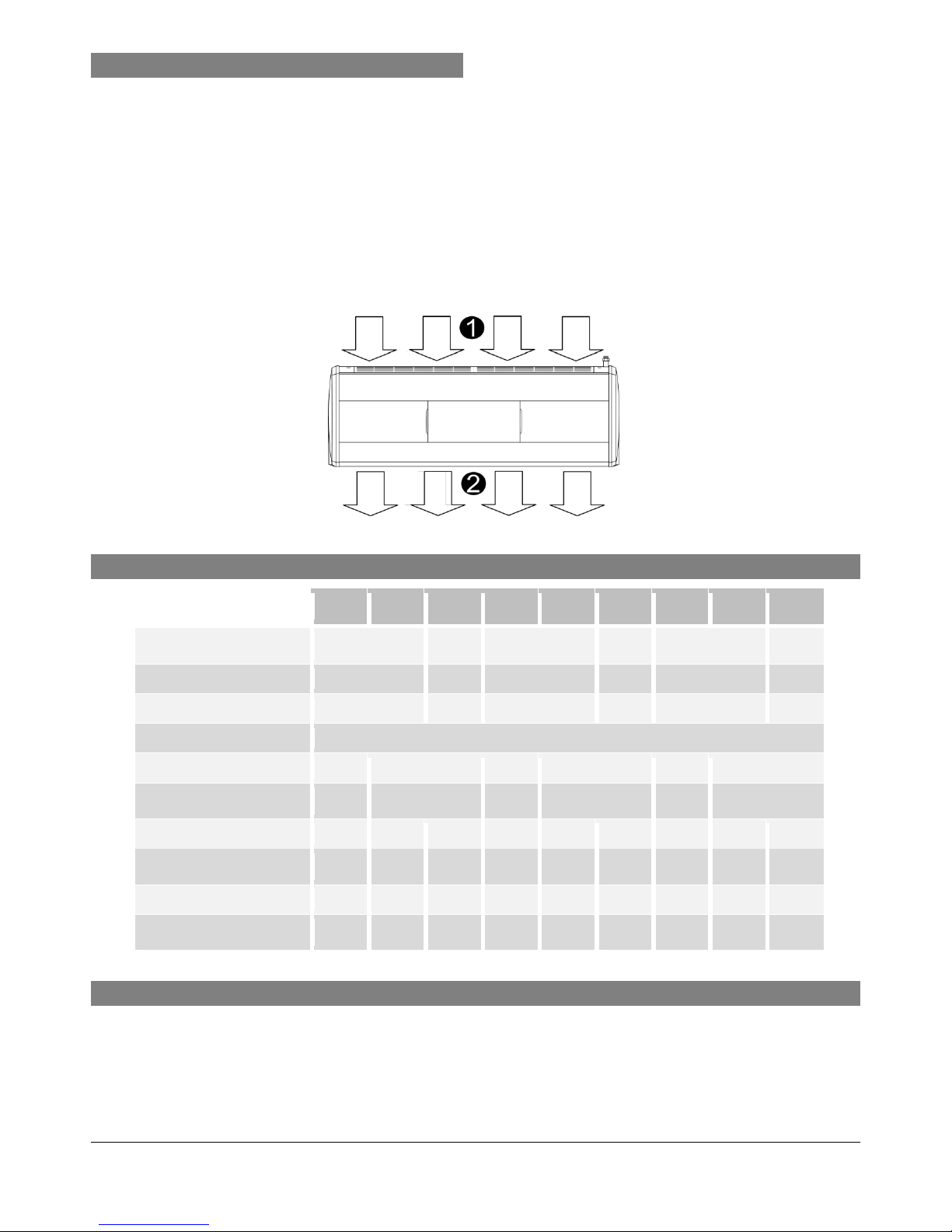
2.1.CONSTRUCTION................................................................. 3
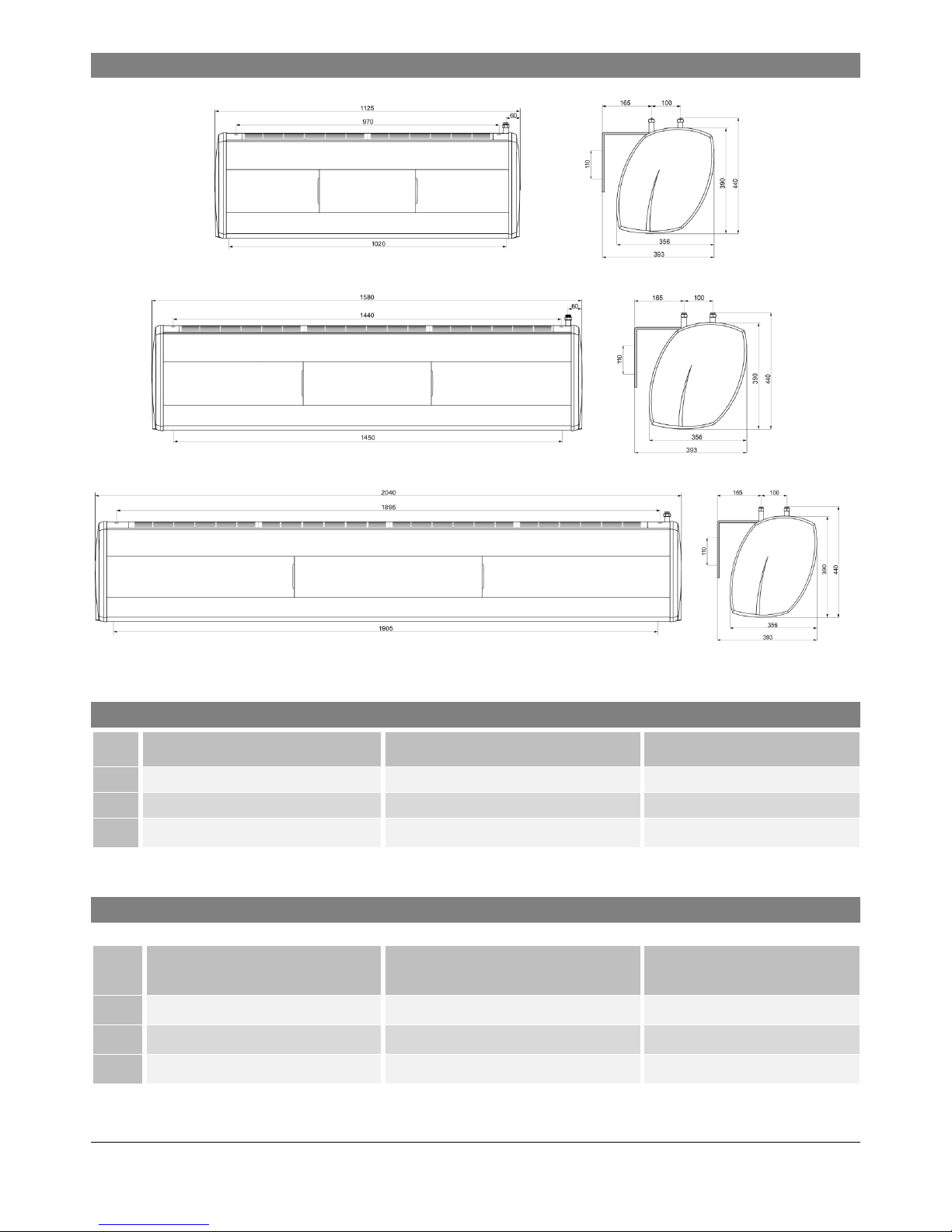
2.2.DIMENSIONS.......................................................................4
2.3.ACOUSTIC PRESSURE LEVEL...........................................4
2.4.AIR VOLUME........................................................................ 4
2.5.NOMOGRAM OF AIR FLOW SPEED...................................5
3. HEAT OUTPUT DATA ................................................................ 5
3.1. ELIS A-W-100.....................................................................5
3.2. ELIS A-W-150.....................................................................6
3.1.ELIS A-W-200.......................................................................6
4. INSTALLATION...........................................................................7
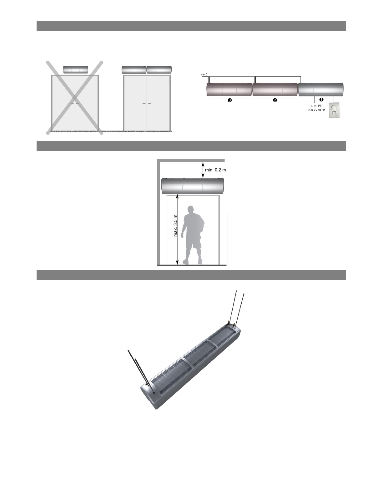
4.1.RECOMMENDATION OF MONTAGE DISTANCES..............7
4.2.MOUNTING BY RODS UNDER THE CEILING..................... 7
4.3.MOUNTING ON THE WALLS BY THE BRACKETS.............. 8
4.4.BRACKETS ..........................................................................8
4.5.STAGES OF INSTALATION.................................................9
5. CONTROL SYSTEMS..............................................................10
5.1.CONTROL ELEMENTS......................................................10
5.2 CONNECTING GUIDE........................................................ 11
5.3.CONTROL SYSTEM........................................................... 11
5.3.1. REGULATION TS –ELIS A-W/N WIRING
DIAGRAMS............................................................12
5.3.2 REGULATION TS –ELIS A-E WIRING DIAGRAMS12
5.3.3 REGULATION T-box - ELIS A-W/N WIRING
DIAGRAMS............................................................13
5.3.4 REGULATION T-box - ELIS A-E WIRING DIAGRAMS
………………………………………………………..13
5.3.5 CONTROL SYSTEM –MASTER-SLAVE
COMMUNICATION ................................................ 14
5.3.6 CONTROL SYSTEM –BMS CONNECTION......... 14
5.3.7. CONTROL SYSTEM –SETTING BMS ADDRESS14
5.3.8. DRV CONTROL SYSTEM –BMS REGISTERS....15
5.4.DOOR CONTACT INSTALLATION..................................... 16
6. GUIDELINES FOR CONNECTION WITH POWER SUPPLY.......16
7. GUIDELINES FOR CONNECTION WITH PIPELINE.................. 16
8. OPERATION............................................................................. 16
9. FILTERS REPLACEMENT........................................................ 17
10. CLEANING AND CONSERVATION.......................................... 17
11. SERVICE..................................................................................17
Thank you for purchasing the ELiS curtain. This operation
manual has been issued by the FLOWAIR GŁOGOWSKI
I BRZEZIŃSKI SP.J. company. The manufacturer reserves the
right to make revisions and changes in the operation manual at
any time and without notice, and also to make changes in the
device without influencing its operation
This manual is an integral part of the device and it must be
delivered to the user together with the device. In order to
ensure correct operation of the equipment, get thoroughly
acquainted with this manual and keep it for the future.
The devices may only be installed and operated in conditions
for which they have been designed. Any other application,
inconsistent with this manual, may lead to the occurrence of
accidents with dangerous consequences. Every effort must be
made in order to eliminate the possibility of improper use of the
device. Access of unauthorized persons to the device should
be restricted, and the operating personnel should be trained.
The manufacturer bears no responsibility for damage resulting
from incorrect installation, improper operating, or not getting
acquainted with the guidelines of the manufacturer manual.
RECOMMENDATIONS AND REQUIRED SAFETY
MEASURES
Get acquainted with this operation manual before
performing any works at the device.
The device may only be installed by qualified personnel
with adequate authorisations and skills.
In the building where ventilation causes underpressure, air
cutrain may have limited efficiency
When performing works at the device, remember about
your own safety.
During installation, electrical connection, connection to the
heating medium, start-up, repairs and maintenance of air
curtains, observe the commonly recognized safety
standards and regulations.

www.flowair.com |3
1. GENERAL INFORMATION
Air Curtain ELiS A is dedicated to install over the door opening,
it provides dynamic barrier cutting out external environment
from indoor.
ELIS types:
ELIS A-W-100 –curtain with water heat exchanger max. range
3 m;
ELIS A-N-100 –curtain without heat exchanger (ambient);
max. range 3 m;
ELIS A-E-100 –curtain with electrical heat exchanger max.
range 3 m;
ELIS A-W-150 –curtain with water heat exchanger max. range
3 m;
ELIS A-N-150 –curtain without heat exchanger (ambient);
max. range 3 m;
ELIS A-E-150 –curtain with electrical heat exchanger max.
range 3 m;
ELIS A-W-200 –curtain with water heat exchanger max. range
3 m;
ELIS A-N-200 –curtain without heat exchanger (ambient);
max. range 3 m;
ELIS A-E-200 –curtain with electrical heat exchanger max.
range 3 m;
air inlet; curtain air outlet;
2. TECHNICAL DATA
A-W-
100
A-N-
100
A-E-
100
A-W-
150
A-N-
150
A-E-
150
A-W-
200
A-N-
200
A-E-
200
Power supply [V/Hz]
230 / 50
3x400 /
50
230 / 50
3x400 /
50
230 / 50
3x400 /
50
Power consumption [kW]
0,17
7
0,25
10,7
0,34
15
Current consumption [A]
0,72
10
1,1
15,5
1,45
21,5
IP / Insulation class
21 / F
Connecting stub [”]
½
-
½
-
½
-
Max. water temperature [oC]
95
-
95
-
95
-
Max. water pressure [MPa]
-
1,6
-
1,6
-
1,6
-
1,6
-
Temperature increase (∆T)
[ºC]*
34
-
25
25
-
21
24
-
18
Weight [kg]
20,9
18,4
21,4
28,3
25,3
28,5
37,1
33,6
39
Weight of unit filled with water
[kg]
22,3
-
-
29,6
-
-
38,8
-
-
* A-W temperature increase at inlet air 10C and heating agent temperature 90/70C / A-E temperature increase at inlet air 10ºC
2.1. CONSTRUCTION
Main construction –aluminium;
Fan –dual inlet radial fan, blades are made of polypropylene, IP20,
Heat exchanger –copper-aluminium, connecting stub ½”; electrical heaters PTC;
Casing –sheet steel RAL 9006 or 9010,
–side panels are made of ABS, 9006 or 9010
–inlet grille PA6GF30,RAL 9007 or 9003
–outlet of air curtain PA6GF30, RAL 7016 or 9003
Brackets –steel, RAL 9007 or 9003

www.flowair.com |4
2.2. DIMENSIONS
ELIS: A-W-100; A-N-100; A-E-100
ELIS: A-W-150; A-N-150; A-E-150
ELIS: A-W-200; A-N-200; A-E-200
2.3. ACOUSTIC PRESSURE LEVEL
step
A-W-100; A-N-100; A-E-100
A-W-150; A-N-150; A-E-150
A-W-200; A-N-200; A-E-200
3
50dB(A)
53dB(A)
55dB(A)
2
43dB(A)
46dB(A)
48dB(A)
1
39dB(A)
42dB(A)
44dB(A)
Acoustic pressure level measured in the room of average sound absorption, capacity 500m3, at the distance of 3 m apart of the unit.
.
2.4. AIR VOLUME
step
A-W-100; A-N-100; A-E-100
A-W-150; A-N-150; A-E-150
A-W-200; A-N-200; A-E-200
3
1500m3/h
2500 m3/h
3500 m3/h
2
1150m3/h
2100 m3/h
2900 m3/h
1
800m3/h
1650 m3/h
2400 m3/h

www.flowair.com |5
2.5. NOMOGRAM OF AIR FLOW SPEED
ELIS A-W-100; A-N-100; A-E-100
ELIS A-W-150; A-N-150; A-E-150; A-W-200; A-N-200; A-E-200
step 1
step 2
step 3
3. HEAT OUTPUT DATA
3.1. ELIS A-W-100
PT
Qw
Δpw
Tp2
PT
Qw
Δpw
Tp2
Tp1
V
kW
l/h
kPa
°C
kW
l/h
kPa
°C
°C
m3/h
Tw1 / Tw2 = 90/70oC
Tw1 / Tw2 = 80/60oC
0
850/1150/1500
14,4/17,7/21,0
637/781/927
4,4/6,4/8,8
47/43/39
12,4/15,2/18,0
545/668/793
3,4/5,0/6,8
40/37/33
5
13,3/16,4/19,4
588/721/857
3,8/5,5/7,6
49/45/41
11,3/13,9/16,5
497/610/724
2,9/4,2/5,7
43/39/36
10
12,3/15,0/17,9
541/663/788
3,3/4,8/6,5
51/47/44
10,3/12,6/15,0
451/553/657
2,4/3,5/4,8
45/41/39
15
11,2/13,7/16,3
494/606/721
2,8/4,0/5,5
53/50/47
9,2/11,3/13,5
405/497/591
2,0/2,9/4,0
47/44/41
20
10,2/12,5/14,8
448/550/654
2,3/3,4/4,6
55/52/49
8,2/10,1/12,0
360/442/526
1,6/2,4/3,2
49/46/44
Tw1 / Tw2 = 70/50oC
Tw1 / Tw2 = 70/40oC
0
850/1150/1500
10,4/12,7/15,1
453/555/659
2,5/3,7/5,0
34/31/28
8,6/10,5/12,5
249/306/363
0,9/1,3/1,7
28/25/23
5
9,3/11,4/13,5
407/498/592
2,1/3,0/4,1
36/33/30
7,5/9,2/10,9
218/268/319
0,7/1,0/1,4
30/28/26
10
8,3/10,1/12,0
361/443/526
1,7/2,4/3,3
38/35/33
6,4/7,9/9,4
186/230/274
0,5/0,8/1,1
31/30/28
15
7,2/8,9/10,5
316/388/461
1,3/1,9/2,6
40/37/35
5,2/6,6/7,9
153/191/229
0,4/0,6/0,8
33/32/30
20
6,2/7,6/9,1
271/334/397
1,0/1,5/2,0
42/40/38
3,9/5,1/6,3
114/150/182
0,2/0,4/0,5
34/33/32
Tw1 / Tw2 = 60/40oC
Tw1 / Tw2 = 50/40oC
0
850/1150/1500
8,3/10,1/12,0
360/442/525
1,8/2,5/3,4
27/24/22
8,0/9,8/11,6
693/850/1010
5,8/8,3/11,4
26/24/21
5
7,2/8,9/10,5
315/386/459
1,4/2,0/2,7
29/27/25
6,9/8,5/10,1
603/740/880
4,5/6,5/8,9
28/26/24
10
6,2/7,6/9,0
269/331/394
1,0/1,5/2,0
31/29/27
5,9/7,3/8,6
515/633/752
3,4/4,9/6,7
30/28/27
15
5,1/6,3/7,5
224/276/329
0,8/1,1/1,5
33/31/30
4,9/6,1/7,2
428/526/626
2,4/3,5/4,8
32/30/29
20
4,1/5,1/6,1
177/220/264
0,5/0,7/1,0
34/33/32
3,9/4,9/5,8
343/422/502
1,6/2,4/3,2
34/32/31
V –air flow
PT –heating capacity
Tp1 –inlet air temperature
Tp2 –outlet air temperature
Tw1 –inlet water temperature
Tw2 –outlet water temperature
Qw –heating water stream
Δpw – water pressure
0,0
1,0
2,0
3,0
4,0
5,0
6,0
7,0
8,0
9,0
0 0,5 1 1,5 2 2,5 3 3,5
Air flow speed [m/s]
distance [m]
0,0
1,0
2,0
3,0
4,0
5,0
6,0
7,0
8,0
0 0,5 1 1,5 2 2,5 3 3,5
Air flow speed [m/s]
distance [m]

www.flowair.com |6
3.2. ELIS A-W-150
PT
Qw
Δpw
Tp2
PT
Qw
Δpw
Tp2
Tp1
V
kW
l/h
kPa
°C
kW
l/h
kPa
°C
°C
m3/h
Tw1 / Tw2 = 90/70oC
Tw1 / Tw2 = 80/60oC
0
1650/2100/2500
17,9/20,7/22,9
791/914/1011
5,3/6,9/8,3
32/29/27
15,3/17,7/19,6
672/777/861
4/5,6/6,3
27/25/23
5
16,8/19,4/21,4
740/855/946
4,7/6,1/7,4
35/32/30
14,1/16,3/18,1
621/718/795
3,5/4,5/5,5
30/28/26
10
15,6/18/20
688/795/881
4,1/5,3/6,5
38/35/34
13/15/16,6
569/658/728
3/3,9/4,7
33/31/30
15
14,4/16,7/18,5
636/735/814
3,5/4,6/5,6
41/38/37
11,8/13,6/15
517/597/661
2,5/3,2/3,9
36/34/33
20
13,2/15,3/17
584/674/748
3/3,9/4,8
43/41/40
10,6/12,2/13,5
464/532/593
2/2,7/3,2
39/37/36
Tw1 / Tw2 = 70/50oC
Tw1 / Tw2 = 70/40oC
0
1650/2100/2500
12,7/14,6/16,2
554/640/709
2,9/3,8/4,6
23/21/19
10,1/11,7/12,9
294/340/377
0,9/1,2/1,5
18/16/15
5
11,5/13,3/14,7
502/580/643
2,4/3,2/3,8
26/24/22
8,8/10/11,4
257/299/331
0,7/1/1,2
21/19/18
10
10,3/11,9/13,2
450/520/576
2/2,6/3,1
28/27/26
7,6/8,8/9,8
220/256/284
0,6/0,7/0,9
23/22/21
15
9,1/10,5/11,6
397/459/508
1,6/2,1/2,5
31/30/29
6,2/7,2/8,1
179/211/235
0,4/0,5/0,6
26/25/24
20
7,84/9,1/10
343/397/439
1,2/1,6/1,9
34/33/32
2,9/5,5/6,2
83/160/181
0,1/0,3/0,4
25/28/27
Tw1 / Tw2 = 60/40oC
Tw1 / Tw2 = 50/40oC
0
1650/2100/2500
10/11,5/12,8
434/502/556
1,9/2,5/3
18/16/15
10/11/12,6
857/992/1099
6,8/8,9/10,7
18/16/15
5
9/10,1/11,2
381/441/489
1,5/2/2,4
21/19/18
8,7/10/11,1
754/872/967
5,4/7/8,5
21/19/18
10
7,5/8,7/9,7
328/380/421
1,2/1,5/1,8
23/22/21
7,5/8,6/9,6
649/751/832
4/5,3/6,4
23/22/21
15
6,3/7,3/8
273/316/351
0,8/1,1/1,3
26/25/24
6,3/7,2/8
543/629/696
3/3,9/4,7
26/25/24
20
4,9/5,7/6,4
214/250/279
0,6/0,7/0,9
29/28/27
5/5,8/6,4
436/504/559
2/2,6/3,1
29/28/28
3.1. ELIS A-W-200
PT
Qw
Δpw
Tp2
PT
Qw
Δpw
Tp2
Tp1
V
kW
l/h
kPa
°C
kW
l/h
kPa
°C
°C
m3/h
Tw1 / Tw2 = 90/70oC
Tw1 / Tw2 = 80/60oC
0
2400/2900/3500
25,7/29/32,2
1135/1271/1419
12/14,5/18
32/29/27
22/24,7/27,6
970/1086/1212
9/11,1/13,6
27/25/23
5
24/27/30
1063/1191/1329
10,4/13/16
35/32/30
20,4/22,9/25,5
898/1006/1122
7,8/9,7/11,8
30/28/27
10
22,5/25,1/28
992/1110/1240
9,2/11,3/14
38/36/34
18,8/21/23,5
825/924/1031
6,7/8,3/10,1
33/31/30
15
20,8/23,3/26
918/1027/1147
7,9/9,8/12
40/38/37
17,1/19,1/21,4
751/841/939
5,7/7/8,5
36/34/33
20
19/21,4/24
844/945/1054
6,8/8,4/10,3
43/42/40
15,4/17,3/19,2
677/758/845
4,7/5,8/7
39/37/36
Tw1 / Tw2 = 70/50oC
Tw1 / Tw2 = 70/40oC
0
2400/2900/3500
18,4/20,6/23
805/902/1007
6,6/8,1/10
23/21/20
15,2/17/19,5
443/496/554
2,3/2,8/3,4
19/17/16
5
16,8/18,8/21
733/821/916
5,6/6,9/8,4
26/24/23
13,5/15,1/16,9
394/441/492
1,8/2,3/2,8
22/20/19
10
15,1/16,9/18,9
660/739/824
4,6/5,7/6,9
29/27/26
11,8/13,2/14,7
343/384/429
1,4/1,8/2,2
24/23/22
15
13,4/15/16,7
586/655/731
3,7/4,6/5,6
31/30/29
10/11,2/12,5
291/326/364
1,1/1,3/1,6
27/26/25
20
11,7/13/14,6
510/571/637
2,9/3,5/4,3
34/33/32
8,1/9,1/10,2
237/266/297
0,7/0,9/1,1
30/29/28
Tw1 / Tw2 = 60/40oC
Tw1 / Tw2 = 50/40oC
0
2400/2900/3500
14,7/16,5/18,4
641/717/801
4,5/5,5/6,7
18/17/16
14,2/16/17,8
1237/1386/1548
15,2/18,8/23
18/16/15
5
13/14,6/16,3
568/636/709
3,6/4,5/5,4
21/20/19
12,5/14/15,7
1092/1223/1366
12,1/14,9/18,3
20/19/18
10
11,3/12,7/14,1
493/552/616
2,8/3,5/4,2
24/23/22
10,9/12,2/13,6
945/1059/1182
9,3/11,5/14
23/22/21
15
9,6/11/12
418/468/522
2/2,6/3,1
27/26/25
9,2/10,3/11,5
797/892/996
6,8/8,4/10,3
26/25/24
20
7,8/8,7/9,8
340/381/425
1,4/1,8/2,2
30/29/28
7,4/8,3/9,3
646/724/808
4,7/5,7/7
29/28/27
V –air flow
PT –heating capacity
Tp1 –inlet air temperature
Tp2 –outlet air temperature
Tw1 –inlet water temperature
Tw2 –outlet water temperature
Qw –heating water stream
Δpw – water pressure

www.flowair.com |7
4. INSTALLATION
Width of doorway must be equal or lower than width of air curtain
outlet (or outlets if air curtains are installed side by side).
While mounting ELiS A side by side it is important to start
from right side (like is shown below), all electrical
conntection should be done before installing following
curtain.
4.1. RECOMMENDATION OF MONTAGE DISTANCES
4.2. MOUNTING BY RODS UNDER THE CEILING
While mounting curtains under the ceiling, 4 rods M8 should be screwed minimum 20 mm deep.

www.flowair.com |8
4.3. MOUNTING ON THE WALLS BY THE BRACKETS
ELIS: A-W-100; A-N-100; A-E-100; A-W-150; A-N-150; A-E-150; A-W-200; A-N-200; A-E-200;
4.4. BRACKETS
Brackets ELiS A
2 x bracket ELiS A
4 x plug (Ø10)*
4 x double threaded screw (M8)*
4 x washer (M8)*
4 x nut (M8)*
4 x allen screw (M8)
* not included

www.flowair.com |9
4.5. STAGES OF INSTALATION
Curtain Type
Distance between brackets [mm]
ELiS A-W-100; ELiS A-E-100; ELiS-A-N-100;
970
ELiS A-W-150; ELiS A-E-150; ELiS-A-N-150;
1440
ELiS A-W-200; ELiS A-E-200; ELiS-A-N-200;
1895
1
2
3

www.flowair.com |10
5. CONTROL SYSTEMS
DRV CONTROL:
Connecting curtains –controlling up to 5 units with one controller;
Connecting to curtain room thermostat*, door contact*, valves with actuator*, speed controller*;
*optional equipment
5.1. CONTROL ELEMENTS
TS - 3-speed fan switch with
room thermostat
Temperature range::
+10 … +30oC
Operatiing temperature range:
0 … +40oC
IP/Insulation class:: IP30
Max current:
inductive 5A, resistive 6A
Power supply: 230V/50Hz
TA - 3-speed fan switch
Operating temperature
range: 0 … +40oC
IP/Insulation class: IP30
Max current:
inductive 4A, resistive 6A
DCm –mechanical door contact
Operating temperature range:: -10 -
+80oC
IP/Insulation class: IP 65
Connectors: 1xNC i 1xNO
Max current:
resistive 10A –inductive 3A
Max Power load: 300Vac or
250Vdc
DCe –magnetic door
contact
Operating temperature
range::
-5 - +60 oC
IP/Insulation class: IP 64
Connectors: NC
Max current::
inductive/resistive 0,5A
Max power Load: 175Vdc
Lenght of cabel: 2m
Max operating contactors
distance: 8mm
SRQ3d ½” – three-way 1/2 valve
with actuator
IP/Insulation class: IP20
Power supply:
200 –240V 50/60Hz
Max water temperature: +93oC
Max water pressure
: 2,1MPa
Kvs: 3,4 m3/h
Opening time: 18 s
SRQ2d ½” –two-way 1/2
valve with actuator
IP/Insulation class: IP20
Power supply:
200 –240V 50/60Hz
Max water temperature:
+93oC
Max water pressure
: 2,1MPa
Kvs: 3,0 m3/h
Opening time: 18 s

www.flowair.com |11
5.2 CONNECTING GUIDE
While connecting ELiS A dismount left side panel and left front panel, cables protract by glands.
5.3. CONTROL SYSTEM
5
Power supply 230V/50Hz;
Connectors for thermostat and fan step switch;
Door contact connector;
Valve actuator connector ELIS-..-W; heaters contactor
connector ELiS-..-E;
BMS system connection;
T-box connectors;
MASTER-SLAVE connectors;
PT-1000 connectors;
LED INDICATORS:
G1, G2, G3 –signalize number of fan speed operating
S1, S2, S3 –signalize number of set fan speed
T –signalize of valve set
DC –signalize of door contact set
OPEN, CLOSE –signalize valve actuator
WORK –signalize of software working
SW3 –operating mode switch (default settings)
1
Device function
selection
BMS Address
adjustment
2
MASTER mode
operating
SLAVE mode
operating
3
Curtain
Heater (DUO)
4
ELiS-..-W/N
ELiS-..-E
5
K1 Programme*
K2 Programme**
6
Operating with
thermostat
Operating w/o
thermostat
*K1 programme –Signal from door switch or thermostat is
main signal for the device to run
**K2 programme –Signal from door switch is main signal for
the device to run and thermostat is in charge of valve/heaters

www.flowair.com |12
5.3.1.REGULATION TS –ELIS A-W/N WIRING DIAGRAMS
Power supply 230V/50Hz (OMY 3x1mm2)
Air curtain step switch with thermostat TS (OMY 5x0,5mm2)
Heat - heating mode
Fan - room thermostat deactivated
Cool - cooling mode
Door contact DCe/DCm (door closed –contacts opened; door opened –contacts closed)
Valve with actuator SRSQ3d (OMY 3x0,5mm2) or SRQ (OMY 3x0,5mm2)
A –Exchanger water supply
AB –Valve water supply
B –Return pipe water supply
5.3.2 REGULATION TS –ELIS A-E WIRING DIAGRAMS
Power supply 3x400V/50Hz
ELiS A-E-100 (min. 5x4 mm2) (Overcurrent B16)
ELiS A-E-150 (min. 5x6 mm2) (Overcurrent B20)
ELiS A-E-200 (min. 5x6 mm2) (Overcurrent B25)
Air curtain step switch with thermostat TS (OMY 5x0,5mm2)
HEAT- heating mode
FAN - room thermostat deactivated
COOL - cooling mode
Door contact DCe/DCm (door closed –contacts opened; door opened –contacts closed)
ATTENTION:
Switch 4 on SW3 to the position “E” and then restart the system switching it off for 5 seconds. Each time the device is switched
off the heaters are being cooled for next 15 seconds

www.flowair.com |13
5.3.3 REGULATION T-box - ELIS A-W/N WIRING DIAGRAMS
Power supply 230V/50Hz (OMY 3x1mm2)
T-box (OMY 4x0,5mm2)
Door contact DCe/DCm (door closed –contacts opened; door opened –contacts closed)
Valve with actuator SRSQ3d (OMY 3x0,5mm2) or SRQ (OMY 3x0,5mm2)
A –Exchanger water supply
AB –Valve water supply
B –Return pipe water supply
5.3.4 REGULATION T-box - ELIS A-E WIRING DIAGRAMS
Power supply 3x400V/50Hz
ELiS A-E-100 (min. 5x4 mm2) (Overcurrent B16)
ELiS A-E-150 (min. 5x6 mm2) (Overcurrent B20)
ELiS A-E-200 (min. 5x6 mm2) (Overcurrent B25)
T-box (OMY 4x0,5mm2)
Door contact DCe/DCm (door closed –contacts opened; door opened –contacts closed)
ATTENTION:
Switch 4 on SW3 to the position “E” and then restart the system switching it off for 5 seconds. Each time the device is switched
off the heaters are being cooled for next 15 seconds.

www.flowair.com |14
5.3.5 CONTROL SYSTEM –MASTER-SLAVE COMMUNICATION
Electrical air curtain chaining provides control from 1 to 5 devices using one T-box or TS.
Electrical air curtain chaining might be done by cable OMY 3x0,5mm2 using connectors CURTAIN IN; CURTAIN OUT.
Connecting units among themselves ensure transfer of controlling signals. Whatever each curtain need
to be supplied directly.
Switch 2 on SW3 set In position:
–For MASTER curtain
–For SLAVE curtain
5.3.6 CONTROL SYSTEM –BMS CONNECTION
DRV driver has a possibility to be connected to integrated Building Management System (BMS).
Parameters:
Name
Description
Physical layer
RS485
Protocol
MODBUS-RTU
Baud rate
38400 [bps]
Parity
Even
Data bits
8
STOP bits
1
Connection must be made using 3-poliges wire to connectors:
IN-A; IN-B; GND (SIGNAL GROUND)
UWAGA: Dla ostatniego urządzenia pracującego w sieci BMS wymagane jest ustawienie przełącznika SW2 w prawą pozycję.
5.3.7. CONTROL SYSTEM –SETTING BMS ADDRESS
There is a possibility to set 31 addresses which are set binary on SW1 switch:
1
2
3
4
5
6
B0
B1
B2
B3
B4
Address
1
2
3
...
31
Switch down
Switch up

www.flowair.com |15
5.3.8. DRV CONTROL SYSTEM –BMS REGISTERS
Holding Register Data (read & write)
Lp.
Adres rejestru
Name of parameter
Min
Max
Description
1
0x04
CurtainFanSpeedRef
0
3
Set value for curtain`s fan
0
FAN_SPEED0
Fan is off
1
FAN_SPEED1
1st step of fan is on
2
FAN_SPEED2
2nd step of fan is on
3
FAN_SPEED3
3rd step of fan is on
2
0x05
CurtainHeatRef
0
1
Set value for thermostat
0
HEAT_OFF
Curtain`s thermostat is off
1
HEAT_ON
Curtain`s thermostat is on
5
0x08
ContactDoor
0
1
Set value for door contact
0
DOOR_CLOSE
Door is closed
1
DOOR_OPEN
Door is opend
Inputs Register Data (write)
Lp.
Adres rejestru
Nazwa parametru
Min
Max
Opis
1
0x04
CurtainFanSpeed
0
3
Curent fan step
0
FAN_SPEED0
Fan is off
1
FAN_SPEED1
1st step of fan is on
2
FAN_SPEED2
2nd step of fan is on
3
FAN_SPEED3
3rd step of fan is on
2
0x05
CurtainValveState
0
2
Current Valve status
1
VALVE_CLOSE
Valve closing
2
VALVE_OPEN
Valve opening
5
0x08
ContactDoor
0
1
Set value for door contact
0
DOOR_CLOSE
Door is closed
1
DOOR_OPEN
Door is open

www.flowair.com |16
5.4. DOOR CONTACT INSTALLATION
Sample of door contact installation
DCm –In case of installation in way which is show on drawing
below, connectors 21 and 22 need to be used
Hinged doors
Dce –In case of installation in way which is show on drawing
below, cable yellow and green need to be used. Other cables
must be isolated.
Hinged door Sliding doors
6. GUIDELINES FOR CONNECTION WITH POWER
SUPPLY
Before connecting the power supply check the correctness of
connection of the fan motor and the controllers. These
connections should be executed in accordance with their
technical documentation.
Before connecting the power supply check whether the
mains voltage is in accordance with the voltage on the device
data shield.
The electrical system supplying the fan motor should be
additionally protected with a circuit breaker against the effects
of a possible short-circuit in the system
Starting the device without connecting the ground conductor
is forbidden.
7. GUIDELINES FOR CONNECTION WITH PIPELINE
The connection should be executed in a way which does
not induce stresses.
It is recommended to install vent valves at the highest point
of the system.
The system should be executed so that, in the case of a
failure, it is possible to disassemble the device. For this
purpose it is best to use shut-off valves just by the device.
The system with the heating medium must be protected
against an increase of the heating medium pressure above
the permissible value (1.6 MPa).
While screwing exchanger to pipeline - connecting stubs
has to be hold by wrench.
8. OPERATION
The device is designed for operation inside buildings, at
temperatures above 0oC. In low temperatures (below 0ºC)
there is a danger of freezing of the medium.
The manufacturer bears no responsibility for damage of
the heat exchanger resulting from freezing of the medium
in the exchanger. It is forbidden to place any objects on the
heater or to hang any objects on the connecting stubs.
The device must be inspected periodically. In the case of
incorrect operation of the device it should be switched off
immediately.
It is forbidden to use a damaged device. The manufacturer
bears no responsibility for damage resulting from the use
of a damaged device.
If it is necessary to clean the exchanger, be careful not to
damage the aluminium lamellas.
For the time of performing inspection or cleaning the
device, the electrical power supply should be
disconnected.
In case water is drained from the device for a longer period
of time, the exchanger tubes should be emptied with
compressed air.

www.flowair.com |17
9. FILTERS REPLACEMENT
Elis curtains can be equipped with EU2 filters. Filters need to
be replaced periodically. Filled filters can causes in Air flow
drop.
Replacing of filters step by step:
1. Dismount inlet grill guard (unscrew the screws).
2. Dismount filters holders by unscrewing screws
3. Install grill guard
10. CLEANING AND CONSERVATION
Periodically need to be checked exchanger condition.
Exchanger filled with dirt causes in heat output and air flow
drop.
If cleaning of heat exchanger is needed use listed guidelines.
Disconnect power supply of unit.
Dismount inlet grill guard
It is recommended to use pressured air to clean the
exchanger, air stream need to be directed perpendicular to
exchanger and moved along lamellas.
It is prohibited to use water or sharp items to clean
exchanger.
Other installed equipment do not need be cleaned.
11.SERVICE
In the case of any irregularities in the device operation, please
contact the manufacturer’s service department.
The manufacturer bears no responsibility for operating the
device in a manner inconsistent with its purpose, by persons
not authorized for this, and for damage resulting from this!
Made in Poland
Made in EU
Manufacturer: FLOWAIR GŁOGOWSKI I BRZEZIŃSKI SP.J.
ul. Chwaszczyńska 151E, 81-571 Gdynia
phone. +48 58 669 82 20, fax.: +48 58 627 57 21
e-mail: [email protected]
www.flowair.com

www.flowair.com |18
DEKLARACJA ZGODNOŚCI WE / Declaration of Conformity
Producent / Manufacturer:
FLOWAIR GŁOGOWSKI I BRZEZIŃSKI SP.J.
Biuro / Office: Chwaszczyńska 151E, 81-571 Gdynia
tel. (058) 669 82 20
tel./fax: (058) 627 57 21
www.flowair.pl
deklaruje, że / hereby confirms, that
nazwa / device name:
Kurtyna powietrzna / Air curtain
modele / models:
ELIS DUO, ELIS A,
typ / types:
ELIS A-W-100 ; ELIS A-N-100 ; ELIS A-E-100 ; ELIS A-W-150 ; ELIS A-N-150 ;
ELIS A-E-150; ELIS A-W-200; ELIS A-N-200; ELIS A-E-200;
ELIS A-W-100/AF ; ELIS A-W-100/L ; ELIS A-N-100/AF ; ELIS A-N-100/L ;
ELIS A-E-100/AF ; ELIS A-E-100/L ; ELIS A-W-150/AF ; ELIS A-W-150/L ;
ELIS A-N-150/AF ; ELIS A-N-150/L ; ELIS A-E-150/AF ; ELIS A-E-150/L ;
ELIS A-W-200/AF ; ELIS A-W-200/L ; ELIS A-N-200/AF ; ELIS A-N-200/L ;
ELIS A-E-200/AF ; ELIS A-E-200/L ;
ELIS DUO; ELIS DUO EL; ELiS DUO-W-100; ELiS DUO-W-200; ELIS DUO-E-100
data wprowadzenia produktu do
obrotu / product launch date:
2014
jest zgodna z zasadniczymi
wymaganiami / was produced in
accordance to the following
European Directives:
dyrektywy / directives MD 2006/42/WE;
dyrektywy / directives EMC 2004/108/WE
oraz zharmonizowanymi z tymi
dyrektywami normami / and
harmonized norms, with above
directives:
PN-EN 60204-1:2010 –Bezpieczeństwo maszyn - Wyposażenie elektryczne maszyn
Część 1: Wymagania ogólne / Safety of machinery - Electrical equipment of machines -
Part 1: General requirements
PN-EN 60335-1:2012 –Elektryczny sprzęt do użytku domowego i podobnego -
Bezpieczeństwo użytkowania Część 1: Wymagania ogólne / Household and similar
electrical appliances - Safety - Part 1: General requirements
PN-EN 60335-2-80:2007 –Elektryczny sprzęt do użytku domowego i podobnego -
Bezpieczeństwo użytkowania Część 2-80: Wymagania szczegółowe dotyczące
wentylatorów / Household and similar electrical appliances - Safety –Part 2-30:
Particular requirements for room heaters
PN-EN 60034-1:2011 –Maszyny elektryczne wirujące Część 1: Dane znamionowe i
parametry / Rotating electrical machines –Part 1: Rating and performance

www.flowair.com |19
PN-EN 60034-5:2004 /A1:2009 –Maszyny elektryczne wirujące Część 5: Stopnie
ochrony zapewniane przez rozwiązania konstrukcyjne maszyn elektrycznych wirujących
(kod IP) –Klasyfikacja / Rotating electrical machines –Part 5: Degrees of protection
provided by the integral design of rotating electrical machines (IP code). Classification.
PN-EN 60034-8:2007 –Maszyny elektryczne wirujące Część 8: Oznaczanie
wyprowadzeń i kierunek wirowania maszyn wirujących / Rotating electrical machines –
Part 8: Terminal markings and direction of rotation.
PN-EN 60034-9:2009 –Maszyny elektryczne wirujące Część 9: Dopuszczalne poziomy
hałasu / Rotating electrical machines –Part 9: Noise limits.
PN-EN 61000-6-1:2008 –Kompatybilność elektromagnetyczna (EMC) Część 6-1: Normy
ogólne - Odporność w środowiskach: mieszkalnym, handlowym i lekko
uprzemysłowionym / Electromagnetic compatibility (EMC) Part 6-1: Generic standards.
Immunity for residential, commercial and light-industrial environments.
PN-EN 61000-6-2:2008 –Kompatybilność elektromagnetyczna (EMC) Część 6-2: Normy
ogólne –Odporność w środowiskach przemysłowych / Electromagnetic compatibility
(EMC) - Part 6-2: Generic standards. Immunity for industrial environments.
PN-EN 61000-6-3:2008 –Kompatybilność elektromagnetyczna (EMC) Część 6-3: Normy
ogólne – Norma emisji w środowiskach: mieszkalnym, handlowym i lekko
uprzemysłowionym / Electromagnetic compatibility (EMC) - Part 6-3: Generic standards
- Emission standard for residential, commercial and light-industrial environments.
PN-EN 61000-6-4:2008 –Kompatybilność elektromagnetyczna (EMC) Część 6-4: Normy
ogólne - Norma emisji w środowiskach przemysłowych / Electromagnetic compatibility
(EMC) - Part 6-4: Generic standards - Emission standard for industrial environments.
Gdynia, 01.04.2012
Product Manager
Dunajski Maciej
Other manuals for ELIS A-W-100
1
This manual suits for next models
8
Table of contents
Other flowair Air Conditioner manuals
Popular Air Conditioner manuals by other brands

Honeywell
Honeywell CL20AE user manual

Johnson Controls
Johnson Controls York VIR 40A installation instructions

GE
GE AGE07 Owner's manual and installation instructions

Arbonia
Arbonia SABIANA OCEAN Series Installation and maintenance manual

DeLonghi
DeLonghi EX Series Instructions for use

Kaden
Kaden KSI R32 owner's manual