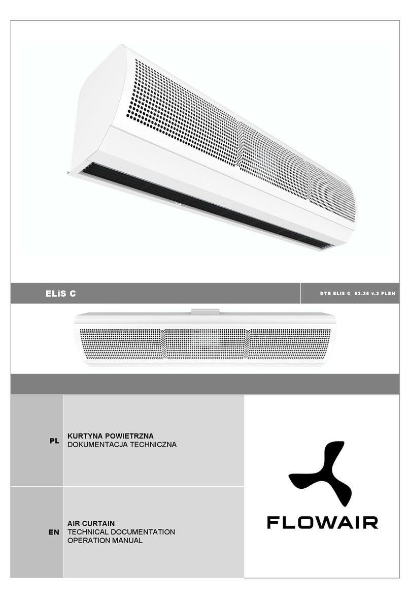
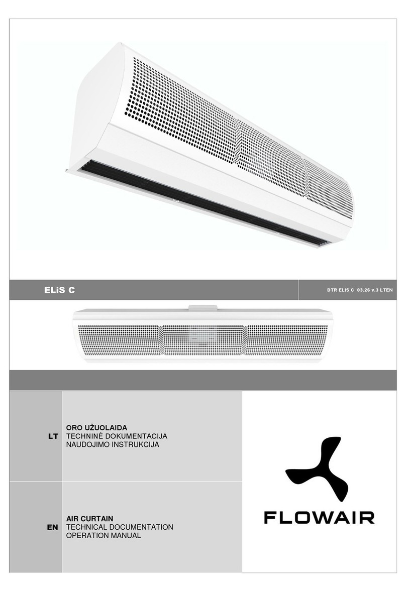
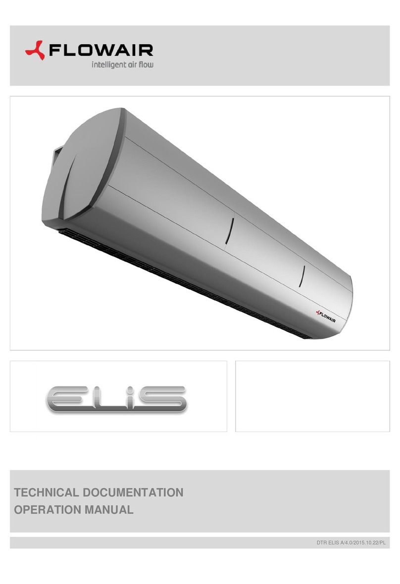
flowair ELIS DUO User manual

TECHNICAL DOCUMENTATION
OPERATION MANUAL
DTR ELIS DUO/R/T /6.0/2013.02.15/EN

www.flowair.com |2
Table Of Contents
1. GENERAL INFORMATION.........................................................3
2. TECHNICAL DATA ..................................................................... 3
2.1.CONSTRUCTION................................................................. 3
2.2.DIMENSIONS.......................................................................4
2.3.ACOUSTIC PRESSURE LEVEL...........................................4
2.4.AIR VOLUME........................................................................ 5
2.5.NOMOGRAM OF AIR FLOW SPEED...................................5
3. HEAT OUTPUT DATA ................................................................ 6
3.1.AIR CURTAIN - FAN HEATER ELIS DUO............................6
3.2.AIR CURTAIN ELIS R1-W-100 .............................................7
3.3.AIR CURTAIN ELIS R3-W-100 .............................................7
3.4.AIR CURTAIN ELIS T2-W-100..............................................8
3.5.AIR CURTAIN ELIS T2-W-150..............................................8
3.6.AIR CURTAIN ELIS T2-W-200..............................................9
4. INSTALLATION...........................................................................9
4.1.RECOMMENDATION OF MONTAGE DISTANCES..............9
4.2.MOUNTING BY RODS UNDER THE CEILING................... 10
4.3.MOUNTING ON THE WALLS BY THE BRACKETS............ 10
4.4.ELEMENTS INCLUDED IN BRACKET SET DUO/R / T ...... 10
4.5.STAGES OF INSTALATION............................................... 11
4.6.VERTICAL INSTALLATIONWITH BRACKETS................... 13
5. CONTROL SYSTEMS............................................................... 14
5.1.CONTROL ACCESSORIES................................................14
5.2.CONNECTING GUIDE - ELIS DUO.................................... 15
5.3.ELIS DUO CONTROL SYSTEM .........................................16
5.3.1.SET TIME DELAY OF IDLE SPEED S1 AND VALVE
ACTUATOR OPERATING S4.................................... 17
5.3.2.SET IDLE SPEED OF AIR CURTAIN FANS
SECTION S2............................................................. 17
5.3.3.SET OPERATING MODE S3.....................................17
5.3.4.ELECTRIC SCHEME ELIS DUO ............................... 19
5.3.5.ELIS DUO UNITS CHAINING...................................19
5.4.ELIS R and T –AF-TYPE CONTROL SYSTEM..................20
5.4.1.SET TIME DELAY OF IDLE SPEED S1 AND VALVE
ACTUATOR OPERATING S4.................................... 21
5.4.2.SET IDLE SPEED OF AIR CURTAIN FANS SECTION
S2 21
5.4.3.S3 OPERATION MODE SET.....................................21
5.4.4.AF ELECTRIC SCHEME........................................... 22
5.4.5.AF –TYPE AIR CURTAINS CHAINING.....................22
5.4.6.AF CONTROL SYSTEM –BMS CONNECTING....... 23
5.4.7.AF CONTROL SYSTEM –BMS ADDRESING..........23
5.4.8.AF CONTROL SYSTEM –BMS RECORDS.............24
5.4.9.AF CONTROL SYSTEM –MASTER-SLAVE
CONNECTING ..........................................................25
5.5.ELIS R and T –L-TYPE CONTROL SYSTEM.....................26
5.5.1. L - ELECTRIC SCHEME........................................... 26
5.5.2. L-TYPE CONTROL SYSTEM....................................27
5.6.DOOR CONTACT INSTALLATION..................................... 28
6. GUIDELINES FOR CONNECTION WITH POWER SUPPLY .... 28
7. GUIDELINES FOR CONNECTION WITH PIPELINE................. 28
8. OPERATION............................................................................. 28
9. FILTERS REPLACEMENT........................................................ 29
10. CLEANING AND CONSERVATION..........................................29
11. SERVICE.................................................................................. 29
Thank you for purchasing the ELiS curtain. This operation
manual has been issued by the FLOWAIR GŁOGOWSKI
I BRZEZIŃSKI SP.J. company. The manufacturer reserves the
right to make revisions and changes in the operation manual at
any time and without notice, and also to make changes in the
device without influencing its operation
This manual is an integral part of the device and it must be
delivered to the user together with the device. In order to
ensure correct operation of the equipment, get thoroughly
acquainted with this manual and keep it for the future.
The devices may only be installed and operated in conditions
for which they have been designed. Any other application,
inconsistent with this manual, may lead to the occurrence of
accidents with dangerous consequences. Every effort must be
made in order to eliminate the possibility of improper use of the
device. Access of unauthorized persons to the device should
be restricted, and the operating personnel should be trained.
The manufacturer bears no responsibility for damage resulting
from incorrect installation, improper operating, or not getting
acquainted with the guidelines of the manufacturer manual.
RECOMMENDATIONS AND REQUIRED SAFETY
MEASURES
Get acquainted with this operation manual before
performing any works at the device.
The device may only be installed by qualified personnel
with adequate authorisations and skills.
When performing works at the device, remember about
your own safety.
During installation, electrical connection, connection to the
heating medium, start-up, repairs and maintenance of air
curtains, observe the commonly recognized safety
standards and regulations.

www.flowair.com |3
1. GENERAL INFORMATION
Air Curtain - Fan Heater Elis Duo is dedicated to install over
the door opening, it provides dynamic barrier cutting out
external environment from indoor.
ELIS DUO oppositely of others types of ELiS curtains are
equipped with unit heater, which is responsible for heating up
area.
ELIS types:
ELIS DUO –Air Curtain - Fan Heater: air curtain range 2,5m,
unit heater range 8m;
ELIS R1-W-100
curtain with water heat exchanger max. range 2,5m;
ELIS R3-W-100
curtain with water heat exchanger max. range 3,5m;
ELIS R1-N-100
curtain without heat exchanger (ambient); max. range 2,5m;
ELIS R3-N-100
curtain without heat exchanger (ambient); max. range 3,5m;
ELIS T2-W-100
curtain with water heat exchanger max. range 3,5m;
ELIS T2-N-100
curtain without heat exchanger (ambient); max. range 3,5m;
ELIS T2-W-150
curtain with water heat exchanger max. range 3,5m;
ELIS T2-N-150
curtain without heat exchanger (ambient); max. range 3,5m;
ELIS T2-W-200
curtain with water heat exchanger max. range 3,5m;
ELIS T2-N-200
curtain without heat exchanger (ambient); max. range 3,5m.
air inlet; curtain air outlet; heater air outlet (ELIS DUO only)
2. TECHNICAL DATA
DUO
R3-W-
100
R3-N-
100
R1-W-
100
R1-N-
100
T2-W-
100
T2-N-
100
T2-W-
150
T2-N-
150
T2-W-
200
T2-N-
200
Power supply [V/Hz]
230V / 50Hz
Current consumption [A]
1,1
0,72
1,1
1,45
Power consumption [W]
250
165
250
335
IP / Insulation class
21 / F
Max. water temperature
[oC]
95
95
-
95
-
95
-
95
-
95
-
Max. water pressure [MPa]
1,6
1,6
-
1,6
-
1,6
-
1,6
-
1,6
-
Connecting stub [”]
½
½
-
½
-
½
-
½
-
½
-
Weight [kg]
33
32
28,5
29
25,5
24
20,5
34,3
29,9
46,8
42,1
Weight of unit filled with
water [kg]
34,2
33,2
-
30,2
-
25,2
-
35,9
-
48,2
-
2.1. CONSTRUCTION
Main construction –galvanized steel
Fan –dual inlet radial fan, blades are made of polypropylene, IP20,
Heat exchanger –one row, copper-aluminium, connecting stub ½”;
Casing –steel sheet powder coated, RAL 9007
- side panels are made of ABS, RAL 7016
- inlet grille PA6GF30 plastic, RAL 9007
- outlet of air curtain PA6GF30 plastic RAL 7016
Brackets –closed structural steel, RAL 9007

www.flowair.com |4
2.2. DIMENSIONS
ELIS: DUO; R3-W-100; R3-N-100; R1-W-100; R1-N-100
ELIS: T2-W-100; T2-N-100
ELIS: T2-W-150; T2-N-150
ELIS: T2-W-200; T2-N-200
2.3. ACOUSTIC PRESSURE LEVEL
step
DUO; R3-W-100; R3-N-100;
T2-W-150; T2-N-150
R1-W-100; R1-N-100;
T2-W-100; T2-N-100
T2-W-200; T2-N-200
3
56dB(A)
53dB(A)
58dB(A)
2
49dB(A)
46dB(A)
51dB(A)
1
45dB(A)
42dB(A)
47dB(A)
Acoustic pressure level measured in the room of average sound absorption, capacity 500m3, at the distance of 3m apart of the unit.

www.flowair.com |5
2.4. AIR VOLUME
step
DUO
R3-W-100;
R3-N-100
R1-W-100;
R1-N-100
T2-W-100;
T2-N-100
T2-W-150;
T2-N-150
T2-W-200;
T2-N-200
Curtain
Heater
3
1400m3/h
700m3/h
2100m3/h
1500m3/h
1770m3/h
2500 m3/h
3500 m3/h
2
1100m3/h
550m3/h
1600m3/h
1150m3/h
1340m3/h
2100 m3/h
2900 m3/h
1
800m3/h
400m3/h
1200m3/h
850m3/h
1020m3/h
1650 m3/h
2400 m3/h
2.5. NOMOGRAM OF AIR FLOW SPEED
ELIS DUO air curtain section
ELIS DUO fan heater section
Air flow speed [m/s]
distance [m]
Air flow speed [m/s]
distance [m]
ELIS R1-W-100; R1-N-100
ELIS R3-W-100; R3-N-100
Air flow speed [m/s]
distance [m]
Air flow speed [m/s]
distance [m]
ELIS T2-W-100; T2-N-100
ELIS T2-W-150; T2-N-150; T2-W-200; T2-N-200
Air flow speed [m/s]
distance [m]
Air flow speed [m/s]
distance [m]
step 1
step 2
step 3

www.flowair.com |6
3. HEAT OUTPUT DATA
3.1. AIR CURTAIN - FAN HEATER ELIS DUO
Air curtain section
PT
Qw
Δpw
Tp2
PT
Qw
Δpw
Tp2
Tp1
V
kW
l/h
kPa
°C
kW
l/h
kPa
°C
°C
m3/h
Tw1 / Tw2 = 90/70oC
Tw1 / Tw2 = 80/60oC
0
800/1100/1400
12,1/14,9/17,2
max.1141
max.12,8
42/37/34
10,4/12,8/14,8
max.976
max.9,9
36/32/29
5
11,2/13,7/15,9
44/40/37
9,5/11,7/14,8
38/35/32
10
10,3/12,6/14,7
47/43/40
8,6/10,6/12,3
41/38/35
15
9,4/11,6/13,4
49/46/43
7,8/9,5/11,1
43/40/38
20
8,6/10,5/12,2
52/48/46
6,9/8,5/9,8
46/43/41
Tw1 / Tw2 = 70/50oC
Tw1 / Tw2 = 70/40oC
0
800/1100/1400
8,7/10,7/12,4
max.811
max.7,3
30/27/24
7,2/8,8/10,2
max.447
max.2,5
25/22/20
5
7,8/9,6/11,1
32/30/27
6,3/7,7/9,0
27/25/23
10
6,9/8,5/9,9
35/32/30
5,4/6,7/7,7
29/27/26
15
6,1/7,5/8,7
37/35/33
4,5/5,6/6,5
31/30/29
20
5,2/6,4/7,5
39/37/36
3,5/4,5/5,2
33/32/31
Tw1 / Tw2 = 60/40oC
Tw1 / Tw2 = 50/40oC
0
800/1100/1400
7,0/8,5/9,9
max.646
max.5,0
24/21/20
6,7/8,2/9,5
max.1245
max.16,7
23/21/19
5
6,1/7,5/8,6
26/24/22
5,8/7,2/8,3
26/23/22
10
5,2/6,4/7,4
29/27/25
5,0/6,1/7,1
28/26/25
15
4,3/5,3/6,2
31/29/28
4,2/5,1/5,9
30/29/27
20
3,5/4,3/5,0
33/32/31
3,3/4,1/4,8
32/31/30
Fan heater section
PT
Qw
Δpw
Tp2
PT
Qw
Δpw
Tp2
Tp1
V
kW
l/h
kPa
°C
kW
l/h
kPa
°C
°C
m3/h
Tw1 / Tw2 = 90/70oC
Tw1 / Tw2 = 80/60oC
0
400/550/700
6,1/7,4/8,6
max.1141
max.12,8
42/37/34
5,2/6,4/7,4
max.976
max.9,9
36/32/29
5
5,6/6,9/8,0
44/40/37
4,8/6,4/6,8
38/35/32
10
5,2/6,3/7,3
47/43/40
4,3/5,3/6,1
41/38/35
15
4,7/5,8/6,7
49/46/43
3,9/4,8/5,5
43/40/38
20
4,3/5,3/6,1
52/48/46
3,4/4,2/4,9
46/43/41
Tw1 / Tw2 = 70/50oC
Tw1 / Tw2 = 70/40oC
0
400/550/700
4,4/5,3/6,2
max.811
max.7,3
30/27/24
3,6/4,4/5,1
max.447
max.2,5
25/22/20
5
3,9/4,8/5,6
32/30/27
3,2/3,9/4,5
27/25/23
10
3,5/4,3/4,9
35/32/30
2,7/3,3/3,9
29/27/26
15
3,0/3,7/4,3
37/35/33
2,3/2,8/3,2
31/30/29
20
2,6/3,2/3,7
39/37/36
1,8/2,2/2,6
33/32/31
Tw1 / Tw2 = 60/40oC
Tw1 / Tw2 = 50/40oC
0
400/550/700
3,5/4,3/4,9
max.646
max.5,0
24/21/20
3,4/4,1/4,8
max.1245
max.16,7
23/21/19
5
3,0/3,7/4,3
26/24/22
2,9/3,6/4,2
26/23/22
10
2,6/3,2/3,7
29/27/25
2,5/3,1/3,6
28/26/25
15
2,2/2,7/3,1
31/29/28
2,1/2,6/3,0
30/29/27
20
1,7/2,1/2,5
33/32/31
1,6/2,0/2,4
32/31/30
V –air flow
PT –heating capacity
Tp1 –inlet air temperature
Tp2 –outlet air temperature
Tw1 –inlet water temperature
Tw2 –outlet water temperature
Qw –heating water stream
Δpw – water pressure

www.flowair.com |7
3.2. AIR CURTAIN ELIS R1-W-100
PT
Qw
Δpw
Tp2
PT
Qw
Δpw
Tp2
Tp1
V
kW
l/h
kPa
°C
kW
l/h
kPa
°C
°C
m3/h
Tw1 / Tw2 = 90/70oC
Tw1 / Tw2 = 80/60oC
0
850/1150/1500
14,4/17,7/21,0
637/781/927
4,4/6,4/8,8
47/43/39
12,4/15,2/18,0
545/668/793
3,4/5,0/6,8
40/37/33
5
13,3/16,4/19,4
588/721/857
3,8/5,5/7,6
49/45/41
11,3/13,9/16,5
497/610/724
2,9/4,2/5,7
43/39/36
10
12,3/15,0/17,9
541/663/788
3,3/4,8/6,5
51/47/44
10,3/12,6/15,0
451/553/657
2,4/3,5/4,8
45/41/39
15
11,2/13,7/16,3
494/606/721
2,8/4,0/5,5
53/50/47
9,2/11,3/13,5
405/497/591
2,0/2,9/4,0
47/44/41
20
10,2/12,5/14,8
448/550/654
2,3/3,4/4,6
55/52/49
8,2/10,1/12,0
360/442/526
1,6/2,4/3,2
49/46/44
Tw1 / Tw2 = 70/50oC
Tw1 / Tw2 = 70/40oC
0
850/1150/1500
10,4/12,7/15,1
453/555/659
2,5/3,7/5,0
34/31/28
8,6/10,5/12,5
249/306/363
0,9/1,3/1,7
28/25/23
5
9,3/11,4/13,5
407/498/592
2,1/3,0/4,1
36/33/30
7,5/9,2/10,9
218/268/319
0,7/1,0/1,4
30/28/26
10
8,3/10,1/12,0
361/443/526
1,7/2,4/3,3
38/35/33
6,4/7,9/9,4
186/230/274
0,5/0,8/1,1
31/30/28
15
7,2/8,9/10,5
316/388/461
1,3/1,9/2,6
40/37/35
5,2/6,6/7,9
153/191/229
0,4/0,6/0,8
33/32/30
20
6,2/7,6/9,1
271/334/397
1,0/1,5/2,0
42/40/38
3,9/5,1/6,3
114/150/182
0,2/0,4/0,5
34/33/32
Tw1 / Tw2 = 60/40oC
Tw1 / Tw2 = 50/40oC
0
850/1150/1500
8,3/10,1/12,0
360/442/525
1,8/2,5/3,4
27/24/22
8,0/9,8/11,6
693/850/1010
5,8/8,3/11,4
26/24/21
5
7,2/8,9/10,5
315/386/459
1,4/2,0/2,7
29/27/25
6,9/8,5/10,1
603/740/880
4,5/6,5/8,9
28/26/24
10
6,2/7,6/9,0
269/331/394
1,0/1,5/2,0
31/29/27
5,9/7,3/8,6
515/633/752
3,4/4,9/6,7
30/28/27
15
5,1/6,3/7,5
224/276/329
0,8/1,1/1,5
33/31/30
4,9/6,1/7,2
428/526/626
2,4/3,5/4,8
32/30/29
20
4,1/5,1/6,1
177/220/264
0,5/0,7/1,0
34/33/32
3,9/4,9/5,8
343/422/502
1,6/2,4/3,2
34/32/31
3.3. AIR CURTAIN ELIS R3-W-100
PT
Qw
Δpw
Tp2
PT
Qw
Δpw
Tp2
Tp1
V
kW
l/h
kPa
°C
kW
l/h
kPa
°C
°C
m3/h
Tw1 / Tw2 = 90/70oC
Tw1 / Tw2 = 80/60oC
0
1200/1600/2100
18,2/21,9/25,9
803/965/1141
6,7/9,5/12,8
42/38/34
15,6/18,8/22,2
687/826/976
5,2/7,3/9,9
36/32/29
5
16,8/20,2/23,9
742/893/1056
5,8/8,2/11,1
44/41/37
14,3/17,2/20,3
627/754/892
4,4/6,2/8,4
38/35/32
10
15,5/18,6/22,0
682/821/972
5,0/7,0/9,6
47/43/40
12,9/15,6/18,4
569/684/810
3,7/5,2/7,0
41/38/35
15
14,1/17,0/20,1
624/751/889
4,3/6,0/8,1
49/46/43
11,6/14,0/16,6
511/616/729
3,1/4,3/5,8
43/41/38
20
12,8/15,5/18,3
566/682/808
3,6/5,0/6,8
52/49/46
10,4/12,5/14,8
455/548/649
2,5/3,5/4,7
46/43/41
Tw1 / Tw2 = 70/50oC
Tw1 / Tw2 = 70/40oC
0
1200/1600/2100
13,1/15,7/18,5
571/686/811
3,8/5,4/7,3
30/27/24
10,8/13,0/15,4
315/379/447
1,3/1,9/2,5
25/23/20
5
11,7/14,1/16,7
513/617/729
3,2/4,4/6,0
32/30/27
9,5/11,4/13,5
275/332/392
1,1/1,5/2,0
27/25/23
10
10,4/12,5/14,8
455/548/648
2,6/3,6/4,8
35/32/30
8,1/10,0/11,6
236/285/338
0,8/1,1/1,5
29/28/26
15
9,1/11,0/13,0
399/480/568
2,0/2,8/3,8
37/35/33
6,8/8,2/9,7
196/238/283
0,6/0,8/1,1
31/30/29
20
7,9/9,5/11,2
343/414/490
1,5/2,2/2,9
39/38/36
5,3/6,5/7,8
155/190/228
0,4/0,6/0,8
33/32/31
Tw1 / Tw2 = 60/40oC
Tw1 / Tw2 = 50/40oC
0
1200/1600/2100
10,4/12,6/14,8
454/546/646
2,6/3,7/5,0
24/22/20
10,1/12,1/14,3
874/1052/1245
8,8/12,3/16,7
23/21/19
5
9,1/11,0/13,0
397/478/565
2,1/2,9/3,9
26/24/22
8,8/10,5/12,5
762/917/1085
6,8/9,6/13,0
26/24/22
10
7,8/9,4/11,1
340/410/485
1,6/2,2/3,0
29/27/25
7,5/9,0/10,7
651/784/928
5,1/7,2/9,8
28/26/25
15
6,5/7,9/9,3
284/343/406
1,4/1,6/2,2
31/29/28
6,2/7,5/8,9
542/653/773
3,7/5,2/7,0
30/29/27
20
5,2/6,3/7,5
227/275/327
0,8/1,1/1,5
33/32/31
5,0/6,0/7,1
434/523/620
2,5/3,5/4,7
32/31/30
V –air flow
PT –heating capacity
Tp1 –inlet air temperature
Tp2 –outlet air temperature
Tw1 –inlet water temperature
Tw2 –outlet water temperature
Qw –heating water stream
Δpw – water pressure

www.flowair.com |8
3.4. AIR CURTAIN ELIS T2-W-100
PT
Qw
Δpw
Tp2
PT
Qw
Δpw
Tp2
Tp1
V
kW
l/h
kPa
°C
kW
l/h
kPa
°C
°C
m3/h
Tw1 / Tw2 = 90/70oC
Tw1 / Tw2 = 80/60oC
0
1020/1340/1770
10,5/12,4/14,5
468/540/648
2,7/3,6/4,8
31/27/24
8,9/10,5/12,3
396/468/540
2,0/2,7/3,6
26/23/21
5
9,8/11,5/13,5
432/504/612
2,4/3,2/4,3
33/30/28
8,2/9,7/11,3
360/432/504
1,7/2,3/3,1
29/26/24
10
9,1/10,7/12,6
396/468/540
2,1/2,8/3,7
36/34/31
7,5/8,8/10,3
324/396/468
1,5/2,0/2,6
32/29/27
15
8,4/9,9/11,6
360/432/504
1,8/2,4/3,2
39/37/34
6,8/8,0/9,4
288/360/396
1,2/1,7/2,2
35/32/30
20
7,7/9,1/10,6
324/396/468
1,5/2,0/2,7
42/40/37
6,1/7,1/8,4
252/324/360
1,0/1,4/1,8
37/36/34
Tw1 / Tw2 = 70/50oC
Tw1 / Tw2 = 70/40oC
0
1020/1340/1770
7,3/8,6/10,1
324/360/432
1,4/1,9/2,6
21/19/17
5,5/6,5/7,6
144/180/216
0,4/0,6/0,8
16/14/13
5
6,6/7,7/9,1
288/324/396
1,2/1,6/2,1
24/22/20
4,7/5,6/6,6
144/162/180
0,3/0,4/0,6
18/17/16
10
5,9/6,9/8,1
252/288/360
1,0/1,3/1,7
27/25/23
3,7/4,6/5,5
108/126/144
0,2/0,3/0,4
21/20/19
15
5,1/6,0/7,1
216/252/324
0,8/1,0/1,4
30/28/27
2,1/2,3/4,2
72/90/108
0,1/0,1/0,3
22/21/20
20
4,4/5,2/6,1
180/216/252
0,6/0,8/1,0
33/31/30
1,8/1,9/2,0
36/54/72
0,1/0,1/0,1
25/24/23
Tw1 / Tw2 = 60/40oC
Tw1 / Tw2 = 50/40oC
0
1020/1340/1770
5,6/6,6/7,8
252/288/324
0,9/1,2/1,7
16/15/13
5,7/6,8/7,9
504/576/684
3,4/4,6/6,2
17/15/13
5
4,9/5,8/6,8
216/252/288
0,7/1,0/1,3
19/18/16
5,0/5,9/6,9
432/504/612
2,7/3,6/4,8
20/18/17
10
4,1/4,9/5,7
180/216/252
0,5/0,7/1,0
22/21/20
4,3/5,1/5,9
360/432/504
2,0/2,7/3,6
22/21/20
15
3,3/3,9/4,7
144/180/216
0,4/0,5/0,7
24/23/22
3,6/4,2/4,9
324/360/432
1,5/1,9/2,6
25/24/23
20
1,7/2,9/3,5
72/108/144
0,1/0,3/0,4
27/26/25
2,8/3,3/3,9
252/288/324
1,0/1,3/1,7
28/27/26
3.5. AIR CURTAIN ELIS T2-W-150
PT
Qw
Δpw
Tp2
PT
Qw
Δpw
Tp2
Tp1
V
kW
l/h
kPa
°C
kW
l/h
kPa
°C
°C
m3/h
Tw1 / Tw2 = 90/70oC
Tw1 / Tw2 = 80/60oC
0
1650/2100/2500
15,9/18,3/20,2
684/792/900
4,1/5,3/6,4
29/26/24
13,6/15,6/17,2
612/684/756
3,1/4,1/4,9
24/22/20
5
14,9/17,1/18,9
648/756/828
3,6/4,7/5,7
32/29/27
12,5/14,4/15,9
540/648/684
2,7/3,5/4,2
27/25/24
10
13,9/15,9/17,6
612/720/792
3,2/4,1/5,0
35/32/31
11,5/13,2/14,6
504/576/648
2,3/3,0/3,6
30/29/27
15
12,8/14,7/16,3
576/648/720
2,8/3,6/4,3
38/36/34
10,4/12,0/13,2
468/540/576
1,9/2,5/3,0
34/32/31
20
11,8/13,5/14,9
504/612/648
2,4/3,1/3,7
41/39/37
9,4/10,8/11,9
396/468/540
1,6/2,1/2,5
37/35/34
Tw1 / Tw2 = 70/50oC
Tw1 / Tw2 = 70/40oC
0
1650/2100/2500
11,2/12,9/14,2
504/576/612
2,3/2,9/3,5
20/18/17
8,8/10,2/11,2
252/288/324
0,7/0,9/1,1
16/14/13
5
10,1/11,7/12,9
432/504/576
1,9/2,4/2,9
23/21/20
7,7/8,9/9,8
216/252/288
0,6/0,7/0,9
19/17/16
10
9,1/10,4/11,5
396/468/504
1,5/2,0/2,4
26/25/24
6,5/7,6/8,4
180/216/252
0,4/0,5/0,7
22/21/20
15
8,0/9,2/10,2
360/396/432
1,2/1,6/1,9
29/28/27
5,1/6,1/6,8
144/180/216
0,3/0,4/0,5
24/23/22
20
6,9/8,0/8,8
288/360/396
0,9/1,2/1,5
32/31/30
2,6/2,8/5,0
72/108/144
0,1/0,1/0,3
25/24/23
Tw1 / Tw2 = 60/40oC
Tw1 / Tw2 = 50/40oC
0
1650/2100/2500
8,8/10,1/11,2
396/432/468
1,5/1,9/2,3
16/14/13
8,7/10,1/11,1
756/864/972
5,3/6,9/8,2
16/14/13
5
7,7/8,9/9,8
324/396/432
1,2/1,5/1,8
19/17/16
7,7/8,9/9,8
684/756/864
4,2/5,4/6,5
19/17/16
10
6,6/7,6/8,4
288/324/360
0,9/1,2/1,4
22/21/20
6,6/7,6/8,4
576/648/720
3,2/4,1/4,9
22/21/20
15
5,4/6,3/7,0
252/270/288
0,6/0,8/1,0
25/24/23
5,5/6,4/7,0
468/540/612
2,3/3,0/3,6
25/24/23
20
4,2/4,9/5,5
180/216/252
0,4/0,5/0,6
27/26/25
4,4/5,1/5,6
396/432/504
1,5/2,0/2,4
28/27/26
V –air flow
PT –heating capacity
Tp1 –inlet air temperature
Tp2 –outlet air temperature
Tw1 –inlet water temperature
Tw2 –outlet water temperature
Qw –heating water stream
Δpw – water pressure

www.flowair.com |9
3.6. AIR CURTAIN ELIS T2-W-200
PT
Qw
Δpw
Tp2
PT
Qw
Δpw
Tp2
Tp1
V
kW
l/h
kPa
°C
kW
l/h
kPa
°C
°C
m3/h
Tw1 / Tw2 = 90/70oC
Tw1 / Tw2 = 80/60oC
0
2400/2900/3500
21,5/24,0/26,7
936/1044/1188
8,3/10,2/12,4
27/25/23
18,4/20,6/22,9
828/900/1008
6,4/7,8/9,5
23/21/19
5
20,1/22,5/25,0
900/1008/1116
7,4/9,0/11,0
30/28/26
17,1/19,1/21,2
756/828/936
5,6/6,8/8,3
26/24/23
10
18,8/21,0/23,3
936/936/1044
6,5/8,0/9,7
33/31/30
15,7/17,5/19,5
684/756/864
4,8/5,8/7,1
29/28/26
15
17,4/19,4/21,6
756/864/936
5,7/6,9/8,4
36/35/33
14,3/16,0/17,8
612/720/792
4,0/4,9/6,0
32/31/30
20
16,1/17,9/19,9
720/792/864
4,9/6,0/7,2
39/38/37
12,9/14,4/16,0
576/648/720
3,4/4,1/5,0
36/34/33
Tw1 / Tw2 = 70/50oC
Tw1 / Tw2 = 70/40oC
0
2400/2900/3500
15,4/17,2/19,1
684/756/828
4,7/5,7/7,0
19/18/16
12,7/14,1/15,7
360/396/468
1,6/2,0/2,4
16/14/13
5
14,0/15,6/17,4
612/684/756
4,0/4,8/5,9
22/21/20
11,2/12,6/14,0
324/360/396
1,3/1,6/1,9
19/18/17
10
12,6/14,1/15,6
540/612/684
3,3/4,0/4,8
25/24/23
9,8/10,9/12,2
288/324/360
1,0/1,2/1,5
22/21/20
15
11,2/12,5/13,9
504/540/612
2,7/3,2/3,9
29/28/27
8,3/9,3/10,3
252/270/306
0,8/0,9/1,1
25/24/23
20
9,8/10,9/12,1
432/468/540
2,1/2,5/3,1
32/31/30
6,7/7,5/8,4
180/216/252
0,5/0,6/0,8
28/27/26
Tw1 / Tw2 = 60/40oC
Tw1 / Tw2 = 50/40oC
0
2400/2900/3500
12,3/13,7/15,2
540/612/648
3,2/3,9/4,7
15/14/13
11,9/13,3/14,8
1044/1152/1296
10,8/13,2/16,1
15/14/12
5
10,9/12,1/13,5
468/540/576
2,6/3,1/3,8
18/17/16
10,5/11,7/13,0
900/1008/1116
8,6/10,5/12,8
18/17/16
10
9,4/10,5/11,7
396/468/504
2,0/2,4/3,0
22/21/19
9,1/10,1/11,3
792/864/972
6,6/8,1/9,8
21/20/19
15
8,0/8,9/9,9
360/396/432
1,5/1,8/2,2
25/24/23
7,7/8,6/9,5
684/756/828
4,9/6,0/7,2
24/23/22
20
6,5/7,3/8,1
288/324/360
1,0/1,3/1,5
28/27/26
6,2/7,0/7,7
540/612/684
3,4/4,1/5,0
28/27/26
V –air flow
PT –heating capacity
Tp1 –inlet air temperature
Tp2 –outlet air temperature
Tw1 –inlet water temperature
Tw2 –outlet water temperature
Qw –heating water stream
Δpw – water pressure
4. INSTALLATION
Width of doorway must be equal or lower than width of air curtain
outlet (or outlets if air curtains are installed side by side).
While mounting ELiS DUO or ELiS R side by side it is
important to start from right side (like is shown below), all
electrical conntection should be done before installing
following curtain.
4.1. RECOMMENDATION OF MONTAGE DISTANCES
ELIS: DUO; R1-W-100; R1-N-100
ELIS: R3-W-100; R3-N-100; T2-W-100; T2-N-100;
T2-W-150; T2-N-150; T2-W-200; T2-N-200

www.flowair.com |10
4.2. MOUNTING BY RODS UNDER THE CEILING
While mounting curtains under the ceiling, 4 rods M8 should be screwed minimum 20mm deep (6 rods should be screwed when
mounting T2-W-200 / T2-N-200).
4.3. MOUNTING ON THE WALLS BY THE BRACKETS DUO/R / T
Available possibilities for install DUO/R / T brackets:
DUO/R Brackets (types: DUO; R1-W-100; R1-N-100; R3-W-
100; R3-N-100)
T brackets (types: T2-W-100; T2-N-100; T2-W-150;
T2-N-150; T2-W-200; T2-N-200)
4.4. ELEMENTS INCLUDED IN BRACKET SET DUO/R / T
DUO/R Brackets
T brackets
2x DUO/R bracket
4x plug ∅10
4x double threaded screw M8
12x washer M8
8x nut M8
4x threaded rod M8
4x spacer sleeve
Mounting kit for
T2-W-100 / T2-N-100 /
T2-W-150 / T2-N-150:
2x T bracket
4x plug ∅10
4x double threaded screw M8
12x washer M8
8x nut M8
4x threaded rod M8
2x short spacer sleeve
2x long spacer sleeve
Mounting kit for
T2-W-200 / T2-N-200:
3x T bracket
6x plug ∅10
6x double threaded screw M8
18x washer M8
12x nut M8
6x threaded rod M8
3x short spacer sleeve
3x long spacer sleeve

www.flowair.com |11
4.5. STAGES OF INSTALATION
ELIS DUO; R1-W-100; R1-N-100; R3-W-100; R3-N-100
ELIS T2-W-100; T2-N-100
1
1
2
2
3
3

www.flowair.com |12
ELIS T2-W-150; T2-N-150
ELIS T2-W-200; T2-N-200
1
1
2
2
3
3

www.flowair.com |13
4.6. VERTICAL INSTALLATION WITH BRACKETS
REGARDS ELIS T2-W-100; T2-W-150; T2-W-200; T2-N-100; T2-N-150; T2-N-200;
Set for vertical mounting consists of two metal consoles, among which is retractable curtain. The kit includes upper, lower bracket
and a set of pins with nuts bolts to screw the brackets to the air curtain.
Set for vertical installation should be screwed to the wall. In the air curtains holes screw 2 pin M8 (see section 6 and 7) and then
screw the bracket to the air curtain. Pins should be screwed into the hole minimum 20mm thread length.
1
3
ELIS
Dimension
A[mm]
T2-..-100
965 +/-5
T2-..-150
1465 +/-5
T2-..-200
1965 +/-5
2
4
5
6
7
8

www.flowair.com |14
5. CONTROL SYSTEMS
ELIS DUO control systems ensure listed possibilities:
Independent control of air curtain section and unit heater section;
Connecting miscellaneous equipment e.g.: room thermostat* step switch*, valve with actuator*, door contact*;
Set idle or/and time delay speed;
Control up to 5 unit by one panel;
Connect to BMS.
There are two controls system available (L and AF) for ELiS T and R:
L –TYPE CONTROL:
Continous or Intermittent mode of operating (door contact, thermostat, switch)
Connecting curtains –controlling up to 5 units with one controller;
Connecting to curtain room thermostat*, door contact*, valves with actuator*, speed controller*;
AF-TYPE CONTROL –moreover listed above it ensure:
Set idle or/and time delay speed;
Control up to 5 unit by one panel;
Connect to BMS.
*optional equipment.
5.1. CONTROL ACCESSORIES
TS - 3-speed fan switch with
room thermostat
Temperature range::
+10 … +30oC
Operatiing temperature range:
0 … +40oC
IP/Insulation class:: IP30
Max current:
inductive 2A, resistive 4A
Power supply: 230V/50Hz
TA - 3-speed fan switch
Operating temperature
range: 0 … +40oC
IP/Insulation class: IP30
Max current:
inductive 4A, resistive 6A
DCm –mechanical door contact
Operating temperature range:: -10 -
+80oC
IP/Insulation class: IP 65
Connectors: 1xNC i 1xNO
Max current:
resistive 4A –inductive 10A
Max Power load: 300Vac or
250Vdc
DCe –magnetic door
contact
Operating temperature
range::
-5 - +60 oC
IP/Insulation class: IP 64
Connectors: NC
Max current::
inductive/resistive 0,5A
Max power Load: 175Vdc
Lenght of cabel: 2m
Max operating contactors
distance: 8mm
SRS3d - three-way 1/2 valve with
actuator
IP/Insulation class: IP40
Power supply:
200 –240V 50/60Hz
Max water temperature: +95oC
Max water pressure: 2MPa
Kvs: 3,4
Mounting: exchanger supply pipe
Running time: 7s
SRS - two-way 1/2 valve
with actuator
IP/Insulation class: IP44
Power supply:
200 –240V 50/60Hz
Max water temperature:
+130oC
Max water pressure: 1,6MPa
Kvs: 3,5
Opening time: 2,5min.

www.flowair.com |15
5.2. CONNECTING GUIDE - ELIS DUO
While connecting DUO or R –type ELiS dismount left side panel and left front panel, cables protract by glands.
While connecting T –type ELIS open bottom panel, cables protract by glands.

www.flowair.com |16
5.3. ELIS DUO CONTROL SYSTEM
Power supply 230V/50Hz
Air curtain section fan power supply
Unit heater section fan power supply
Valve actuator
Air curtain control panel
Unit heater control panel
Master / Slave connection
Signalize led:
Power supply (red)
Air curtain step (green)
Unit heater step (green)
Valve actuator operating (green)
Switches :
S4 –Valve operating time delay;
S2 –Idle speed;
S1 –Idle speed time delay;
S3 –Operating mode;
F1 –Fuse 1,6A;
PROGRAMMING STEP BY STEP:
1. Choose operating mode DUO 1 or DUO 2 (S3)
2. Choose controllers
3. Set (depending on needs) additional settings (S1, S2, S4)
ATTENTION:
*DUO 1 - main signal (turning on unit) from TS or DCe/DCm;
**DUO 2 - main signal (turning on unit) from DCe/DCm;
***Multiply settings on S1, S2, S3, S4 from Master unit.

www.flowair.com |17
5.3.1. SET TIME DELAY OF IDLE SPEED S1 AND
VALVE ACTUATOR OPERATING S4
1
2
3
4
Time
1
2
3
4
Time
0
4 min.
30 sec.
4 min.
30 sec.
1 min.
5 min.
1 min.
30 sec.
5 min.
30 sec.
2 min.
6 min.
2 min.
30 sec.
6 min.
30 sec.
3 min.
7 min.
3 min.
30 sec.
7 min.
30 sec.
Switch down position
Switch up position
S1, S4 –default mode: time "0"
5.3.2. SET IDLE SPEED OF AIR CURTAIN FANS
SECTION S2
1
2
3
4
Idle
off
1
2
3
Switch down position
Switch up position
S2 –default mode: „off”.
5.3.3. SET OPERATING MODE S3
1
2
3
4
PRG
Description
DUO 1
Should be chosen while unit is controlled::
Air curtain section:
–door contact and 3-speed fan switch TA.
–or room thermostat with 3-speed fan switch TS.
Unit heater sections by room thermostat with 3-speed fan switch TS.
Switch down position
Switch up position
S3 –default mode: DUO 1
Operating scheme
Ts –set temperature
Tm –measured temperature

www.flowair.com |18
1
2
3
4
PRG
Description
DUO 2
Should be chosen while unit is controlled:
Air curtain section by door contact and room thermostat with 3-speed fan switch TS
Unit heater section by room thermostat with 3-speed fan switch TS.
Switch down position
Switch up position
Operating scheme
Ts –set temperature
Tm –measured temperature
TS N –room thermostat with 3-speed fan switch TS who
controls unit heater should be mounted in space with adequate
temperature inside the room, at the 1,5m height. Is important to
mount that thermostat away from heat source, light, sun rays,
door and windows opening.
TS K - room thermostat with 3-speed fan switch TS who
controls air curtain should be mounted close to doorway, at the
1,5m height.

www.flowair.com |19
5.3.4. ELECTRIC SCHEME ELIS DUO
DUO 1
Power supply 230V/50Hz
(OMY 3x1mm2)
Valve with actuator
SRS3d (OMY 3x0,5mm2) or
SRS (OMY 2x0,5mm2)
Air curtain section step switch
TA (OMY 4x0,5mm2)
Door contact DCe/DCm
Unit heater room thermostat
with step switch TS
(OMY 5x0,5mm2)
A –Exchanger water supply
AB –Valve water supply
B –Return pipe water supply
a –blue
b –black
c –brown
DUO 2
Power supply 230V/50Hz
(OMY 3x1mm2)
Valve with actuator
SRS3d (OMY 3x0,5mm2) or
SRS (OMY 2x0,5mm2)
Air curtain room thermostat with
step switch TS
(OMY 5x0,5mm2)
Door contact DCe/DCm
Unit heater room thermostat
with step switch TS
(OMY 5x0,5mm2)
A –Exchanger water supply
AB –Valve water supply
B –Return pipe water supply
a –blue
b –black
c –brown
5.3.5. ELIS DUO UNITS CHAINING
Electrical connecting execute with:
1. Cable OMY 2x0,5mm2(unscrew
RJ socket), or use
2. Cable equipped with RJ plugs;
Connecting Elis Duo units
among themselves ensure
transfer of controlling signals.
Whatever each EliS Duo need to
be supplied directly with 230V.
Description of configuration
in chapter 5.4.9

www.flowair.com |20
5.4. ELIS R and T –SYSTEM
Power supply 230V/50Hz
Air curtain section fan power supply
Valve actuator
Air curtain control panel
Master / Slave connection
Signalize led:
Power supply (red)
air curtain speed (green)
Valve actuator operating (green)
Switches :
S4 –Valve operating time delay;;
S2 –Idle speed step of air curtain;
S1 –Idle speed time delay;
S3 –Operating mode;
F1 –Fuse 1,6A;
PROGRAMMING STEP BY STEP:
1. Choose operating mode K1 or K2 (S3)
2. Choose controllers
3. Set (depending on needs) additional settings (S1, S2, S4)
ATTENTION:
*K 1 - main signal (turning on unit) from TS or DCe/DCm;
**K 2 - main signal (turning on unit) from DCe/DCm;
***Multiply settings on S1, S2, S3, S4 from Master unit.
Other manuals for ELIS DUO
1
This manual suits for next models
10
Table of contents
Other flowair Air Conditioner manuals
Popular Air Conditioner manuals by other brands

Dettson
Dettson COND-UHD-09 Installation instructions and homeowner's manual

LG
LG MT11AH installation manual

Innova
Innova Innova Filomuro Incasso SLWI Installation and user manual

REMKO
REMKO SKT 521 Operating and installation instructions

Samsung
Samsung SC07APGD user manual

Mitsubishi Electric
Mitsubishi Electric MSZ-A09/A12YV Series installation manual