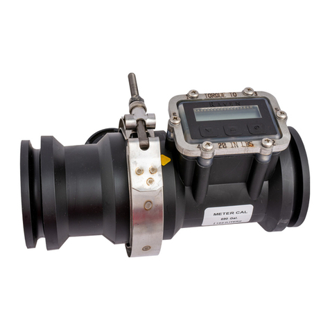
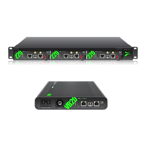
FLOWMAX 30S User manual

Flowmax
®
30S
Ultrasonic
Flowmeter
Operating manual
BA 010E/FM30S/01.18
Valid starting from
Hardware V 2.0
Software V 129

eneral safety instructions Flowmax
30S
2 M I B
General safety instructions
Please always observe the following safety instructions!
Please pay attention to the safety instructions with the following pictograms and
signal words in these operating instructions:
IMPORTANT! indicates situations or cases
which, if not avoided, could result in
damage or failure of the Flowmax 30S
equipment.
WARNIN ! indicates general hazardous
situations or cases which, if not avoided,
could result in serious injury or death.
NOTICE! is used to lead users to helpful
information not related to personal injury.
Intended use
• The flowmeter Flowmax 30S may only be used for measuring the flow of
pure, homogeneous liquids.
• The Flowmax 30S is not intended for use in medical applications.
• The volume flowmeter Flowmax 30S is built operationally safe in
accordance with the latest state of the art technologized developments and
industry standard EN 61010 regulations (corresponds to VDE 0411 “Safety
specifications for electrical measurement, control and laboratory devices”).
• The manufacturer is not liable for any injury, damage or harm due to
inappropriate or unintended use or modifications of the flowmeter.
Conversions and/or changes to the flowmeter may only be made, if they are
expressly performed in accordance with the operating instructions in this
operating manual.
Personnel for installation, commissioning and operation
•
ssembly, electrical installation, commissioning and maintenance of
the flowmeter must be carried out by qualified, trained personnel. The
qualified personnel must have read and understood the operating
instructions in this operating manual and must follow the operating
instructions in this manual.
• The installer has to ensure that the flowmeter is correctly connected
according to the electrical connection diagrams in this operating
manual.
• Serious injury or death from electric shock may occur if wiring,
installation, disassembly or remove of wires is performed while
electrical power is energized
Technological progress
The manufacturer reserves the right to revise, alter, or modify the flowmeter to
the most current technology without special prior notice. Further information
about the latest updates and potential additions to these operating instructions
are available from the manufacturer.
IMPORT NT!
W RNING!
NOTICE!
W RNING!

Flowmax
30S Table of contents
M I B 3
Table of contents
General safety instructions ............................................................................................................. 2
Table of contents ............................................................................................................................. 3
List of Figures .................................................................................................................................. 3
1. Planning information ................................................................................................................ 4
1.1 Areas of application..................................................................................................................................... 4
1.2 Measuring principle ..................................................................................................................................... 4
1.3 Cleaning ...................................................................................................................................................... 5
1.4 Operational safety ....................................................................................................................................... 5
2. ssembly and installation........................................................................................................ 5
2.1 Installation instructions ................................................................................................................................ 5
2.2 Assembly of the flowmeter .......................................................................................................................... 6
2.3 Electrical wiring ........................................................................................................................................... 6
3. Commissioning ......................................................................................................................... 7
3.1 Operation .................................................................................................................................................... 7
3.2 Functionalities of flowmeter and default settings ........................................................................................ 7
3.2.1 pnp-/ npn-logic ..................................................................................................................................... 7
3.2.2 Configuration output 1 .......................................................................................................................... 8
3.2.2.1 Pulse value .................................................................................................................................................... 8
3.2.3 Output 2 ............................................................................................................................................... 9
3.2.4 Creeping suppression .......................................................................................................................... 9
3.3 Overview of default settings ...................................................................................................................... 10
3.4 eneral information................................................................................................................................... 10
4. Exchange of flowmeter .......................................................................................................... 11
5. Technical specifications ........................................................................................................ 12
5.1 Dimensions and weight ............................................................................................................................. 12
5.2 Technical specifications ............................................................................................................................ 13
6. ccessories ............................................................................................................................ 14
7. Shipment ................................................................................................................................. 14
List of Figures
Figure 1: Presentation of the principle of ultrasonic flow measuring ................................................... 4
Figure 2: Connection plug / diamensions ........................................................................................... 6
Figure 3: outputs O1 and O2 are used in npn- and pnp-logic ............................................................. 8

Planning information Flowmax
30S
4 M I B
1. Planning information
1.1 reas of application
The flowmeter Flowmax 30S is particularly suitable for the measurement of
dynamic processes of liquids in a pipe. It is used in beverage dispensing
systems
Its performance features are characterized by the following characteristics:
• no moving parts and therefore no wear
• high reproducibility
• easy cleaning
• safe against manipulation
• compact design
• integrated foam-/empty pipe detection
• excellent chemical resistance
1.2 Measuring principle
It usually takes more energy to swim against the flow than with the flow. The
ultrasonic flow measurement is based on the phase-difference approach:
Two ultrasonic-sensors located opposite from each other alternatively
transmitting and receiving ultrasonic signals. If there is no liquid flow both
sensors receive the transmitted ultrasonic signals in the same phase, i.e.
without phase difference. If liquid is flowing there is a phase shift. It differs when
measured in direction of the flow than when measured against the direction of
the flow. This phase difference is directly proportional to the flow rate.
Figure 1: Presentation of the principle of ultrasonic flow measuring

Flowmax
30S Assembly and installation
M I B 5
1.3 Cleaning
Flowmax 30S has to be cleaned according technical Rules for beverage
dispensing systems TRSK 501“. While cleaning the Flowmax 30S is allowed to
stay in the pipe. The connections need not to be loosened.
1.4 Operational safety
Comprehensive self-tests ensure highest possible safety.
Faults (process or system errors) are output on a digital output or displayed on
the display menu.
The protection class is IP 65.
Flowmax 30S meets the general EMC immunity requirements according to CE,
EN 61000-6-3, EN 61000-4-2, EN 61000-4-3, EN 61000-4-4, EN 61000-4-5, EN
61000-4-6.
Flowmax 30S meets the safety requirements concerning the Protective Extra
Low Voltage directive according to EN 50178, SELV, PELV.
ttention: a max. wire length of 30m has to be complied!
For longer cables a special protection circuit is required!
2. ssembly and installation
2.1 Installation instructions
An arrow is printed on the nameplate on the front of the Flowmax 30S. The
measuring instrument must be mounted so that the product flows through it in
the direction of the arrow. For fastest possible gas detection it is important to
keep the pipe distance from tank to Flowmax 30S as short as possible.
Accurate measurement can only be guaranteed, if the pipe is completely filled
and if it is ensured that the liquid does not outgas.
Notwithstanding it may be advantageous for dosing applications to place the
Flowmax 30S as close as possible to the dosing valve, since tubes increase
their cross-section depending on the system pressure. This may lead to
repeatable differences.
Please note that it is absolutely necessary to have a back pressure of at
least 0.3 bar rel. (corresponds to 3 m water column) at the outlet of the
Flowmax 30S.
Solid matter particles that are carried along may result in measuring errors.
When using pumps, Flowmax 30S must be installed in flow direction behind the
pump, on the pressure side, in order to ensure sufficient pressure. Regard the
maximum pressure step of the Flowmax 30S.
For correct volume flow measurements straight and unobstructed inflow and
outflow zones for Flowmax 30S have to be observed. Starting from the
connection thread these have to be at least:
DN 7 DN 10 DN 15
inlet 5 cm 5 cm 40 cm
outlet 0 cm 0 cm 20 cm
IMPORT NT!
IMPORT NT!
IMPORT NT!

Assembly and installation Flowmax
30S
6 M I B
2.2 ssembly of the flowmeter
In order to fasten the Flowmax 30S to a solid ground it has two bores with
female threads M4 at the front face (for dimensions see section 5, Technical
specifications). The housing of the DN15 version has additional bores on its
backside. Thus, the mounting to an existing construction is possible. Suitable
fixing material for the mounting, e.g. to a wall, can be delivered on demand.
To insulate all surfaces between the connector parts of the hydraulic pipes and
the Flowmax elastic gaskets, e.g. of PVC or silicone, should be used. The union
nuts must be tightly fastened.
2.3 Electrical wiring
Serious injury or death from electric shock may occur if wiring,
installation, disassembly or remove of wires is performed while electrical
power is energized.
lways shut off or disconnect electrical power at service panel and lock
switch or breaker and tag to prevent energizing electrical power during
work or while Flowmax 30S is not assembled and installed.
Wiring installation, disassembly and removal must be performed by
qualified persons experienced and knowledgeable about electrical work.
If the original plug is cut attention must be paid to connection polarity and
operating voltage!
Take care of the plug position when plugging it into the socket!
Pin configuration oft he plug
Figure 2: Connection plug / diamensions
C
ab
l
e
colour
/ PIN
Parameter
Description
white / 2 L+ Power supply: 20...30 VDC / 2 W
grey / 5 L- round: 0 V
brown / 1 Pulse output
npn- and pnp-transistor, max. load 100mA.
With inductive load use freerun diode antiparallel
to coil
blue / 3 Empty pipe
alarm
npn-transistor, max. load 100mA.
With inductive load use freerun diode antiparallel
to coil
black / 4 Communication
Data and configuration port
*
with electronic overload protection
1 2
3
5
4
W RNING!
NOTICE!
NOTICE!
W RNING!

Flowmax
30S Commissioning
M I B 7
3. Commissioning
3.1 Operation
If Flowmax 30S is used as a flow meter in beverage dispensing systems, it does
not require any operation on site since the following parameters are in a factory
setting which ensures an optimum function. The Flowmax 30S can also be
supplied with customer-specific settings.
If necessary, this presetting can be changed individually using the integrated
interface. The external display and programming unit FlowCon 200i is required
for this purpose (see chapter 6, Accessories).
The following parameters may be changed to settings suitable for the individual
conditions:
Output O1 and O2
- pnp-logic
- npn-logic
Configuration output 1
- pulse output (pulse value)
Configuration output 2
- empty pipe alarm
(delay time, switching state with gas or empty pipe)
Creeping suppression
3.2 Functionalities of flowmeter and default settings
3.2.1 pnp-/ npn-logic
Here, a determination is made as to whether a positive signal (pnp) or a mass
signal (npn) is output at the outputs 1 or 2.
pnp-logic => the output switches to 24V, the LOW level is defined by the
master device. HI H potential corresponds to the supply voltage.
npn-logic => the output switches to 0V, the HI H level is defined by the master
device
bipolar (only for output 2) => the output switches both to HI H (supply voltage)
and to LOW

Commissioning Flowmax
30S
8 M I B
The following figure shows how pnp or npn logic works for the configuration
output 1 : pulse output
output 2 : empty pipe alarm
npn-logic pnp-logic
Figure 3: outputs O1 and O2 are used in npn- and pnp-logic
Setting range: pnp-logic, npn-logic
Default setting: npn-logic
3.2.2 Configuration output 1
Output 1 can be used as a pulse or empty pipe alarm output. When pulse output is
selected, the pulse value can be set
Setting range: pulse output, empty pipe alarm
Default setting: pulse output
3.2.2.1 Pulse value
The pulse value determines the flow volumes for which an output pulse will be
emitted.
Choose a configuration which will neither exceed the maximum output
frequency of the Flowmax 30S (10kHz) nor the maximum input frequency of the
control. The pulse / pause ratio is 1:1. The pulse length is limited to 1s.
Exampel: 5.0 ml/pulse
This means: a pulse is output every 5.0 ml
Setting range: 0.1...3000 ml/pulse, in steps of 0.1 ml/pulse
Default setting: 1.0 ml/pulse

Flowmax
30S Commissioning
M I B 9
3.2.3 Output 2
Output 2 is used as line B for RS485 operation, and the vacant state of the
measuring channel can be signaled via the line
For the operation of the RS485 interface, the lines A and B are required, i.e.
output 2 can not be used as a switching output in this case.
Setting range: empty pipe alarm
Default setting: empty pipe alarm
3.2.4 Creeping suppression
The creeping suppression excludes flow measurements that result from
convection in a narrow band around zero, even with a closed valve. At the
factory, the creeping suppression is set at a standard value in relation to the
cross-section of the flowmeter.
Creeping suppression works with a hysteresis of - 25%.
Example: Creeping suppression = 5.0 ml/s
If the flow rate is lower than 3.75 ml/s the pulse output becomes
inactive. If the flow rate exceeds 5 ml/s a pulse is output again and
added to the totalizer.
Setting range: 0.0...400 ml/s, in 0.1 ml/s steps
DN7 DN10 DN15
Default setting: 3.5 ml/s 5.0 ml/s 15.0 ml/s
IMPORT NT!
NOTICE!

Commissioning Flowmax
30S
10 M I B
3.3 Overview of default settings
Func
tion
Default setting
a) pnp-/ npn-logic npn-logic
b) configuration output 1 pulse output
pulse value 1 ml/pulse
c) output 2 empty pipe alarm
d) creeping suppression 3.5 ml/s for DN 7
5.0 ml/s for DN 10
15.0 ml/s for DN 15
3.4 General information
Please check the following before powering the flowmeter for the first time:
• Check the electrical connections and cable allocations.
• Check the installation position of the flowmeter. Is the direction of the arrow
on the housing/name plate and the actual flow direction in the pipe
congruent?
• Is the measurement pipe completely filled with fluid?
• Check the back pressure in the system.
When everything has been checked, switch on power. After 30 minutes with
power running the measuring device reaches the maximum accuracy.
Flowmax 30S is operational!
IMPORT NT!

Flowmax
30S Exchange of flowmeter
M I B 11
4. Exchange of flowmeter
• Switch off power before disconnecting the electrical connections!
• Wiring installation, disassembly and removal must be performed by
qualified persons experienced and knowledgeable about electrical
work.
• Serious injury or death from electric shock may occur if wiring,
installation, disassembly or remove of wires is performed while
electrical power is energized
• Please note that after replacing the flowmeter
a) Specific programming of the previous flowmeter should be noted and
programmed to the new flowmeter
b) when using the dosing function, set a quantity
If the device requires a configuration change, the display and programming unit
FlowCon 200i may be required (see section 6. Accessories).
Repair, hazardous substances
Before sending the flowmeter Flowmax 30S for repair, the following precautions
must be taken:
• Clean all process chemicals from the device. Fully rinse the flow
path. Please pay close attention to the process fittings. ll media
must be removed before returning. This is particularly important, if
the medium to be measured is health hazardous.
Devices judged to be insufficiently cleaned will be returned to sender. No
inspection of device will be done until proper cleaning is completed by user.
Costs due to inadequate cleaning of the instrument for possible disposal or
injury (burns, etc.) will be charged to the sender of the flowmeter into account!
• With the flowmeter send a detailed report describing the failure, the
application and the physical-chemical properties of the medium
parameters. (e.g. a decontamination declaration).
In order to be able to process your repair order quickly and smoothly it is
important that you provide a technical contact person including phone and fax
number as well as e-mail address.
W RNING!
W RNING!
W RNING!

Technical specifications Flowmax
30S
12 M I B
5. Technical specifications
5.1 Dimensions and weight
DN 7 and DN 10
Weight: 700g
All dimensions in [mm]:
DN7: A = 22 DN10: A = 23.5
DN 15
Weight: 800g
M4, 12 deep
for mounting
on a wall
M4, 12 deep for
mounting on a
wall

Flowmax
30S Technical specifications
M I B 13
5.2 Technical specifications
Housing
Nominal Diameter DN 7, DN 10, DN 15
Connection DN 7, 10: ⅝“
DN 15: ¾“
Dimensions incl.
connections DN 7, 10: H: 40.0mm; B: 130.0mm; T: 142.0mm
DN 15: H: 58.0mm; B: 130.0mm; T: 142.0mm
Temperature medium 0...+60°C
Protection class IP 65
Material all parts connected with medium are made of polyethylene (PE)
Weight DN 7, 10: 700g
DN 15: 800g
Nominal pressure PN6
Electronics
Power supply 20...30VDC, 2W
Connection 5-wired cable with plug, length: 5.0m
Temperature environment -20....+60°C
Output 1 Transistor, npn- and pnp-logic, max. 100mA
Configured as: pulse output
Output 2 Transistor, npn- and pnp-logic, max. 100mA
Configured as: empty pipe alarm
Data interface One-wire interface for parametrize
Measuring deviation ±2% o.r. ± 3mm/s (o.r. = of reading),
option ± 1% o.r. ± 3mm/s,
Reference conditions (VDE/VDI 2642)
Measuring range DN 7 100 ml/s
DN 10 200 ml/s
DN 15 1000 ml/s
Repeatability 0.5%
The measuring system Flowmax 30S meets the general EMC immunity requirements
according to CE, EN 61000-6-3, EN 61000-4-2, EN 61000-4-3, EN 61000-4-4, EN
61000-4-5, EN 61000-4-6. It is in conformity with the requirements of the EC directives
and has the CE label.

Accessories Flowmax
30S
14 M I B
6. ccessories
Flowview 2S
Display and supply unit for up to 2 ultrasonic flowmeters Flowmax 30S
Order code 908750
FlowCon 200i
External display and programming unit for use in combination with ultrasonic
flowmeters Flowmax. FlowCon 200i can be used as separated display as fixed
installation for Flowmax.
Order code 908875 (FlowCon 200i for Flowmax 30S)
MP C-141X
Multi-channel processor display with data logger, bus-interfaces and various inputs and
outputs. Datatransmission via USB stick / Ethernet possible.
Order code on request
Tank Disposition MP C D Q-Manager
Software for evaluation of the flow rates registered in the MPAC-141X, further
processing e.g. in Excel
Order code 908720
7. Shipment
• Flowmax 30S

Flowmax
30S Shipment
M I B 15

MIB mbH
Messtechnik und Industrieberatung
Bahnhofstr. 35
D-79206 Breisach
Tel. 0049 / (0)7667 / 20 777 90
Fax 0049 / (0)7667 / 20 777 99
Mail: [email protected]m
Web: www.flowmax.de
Table of contents
Other FLOWMAX Measuring Instrument manuals
