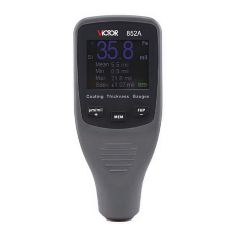
Victor 852A User manual

1
Contents
Chapter one introduction - - - - - - - - - - - - - - - -2
Chapter two application method - - - - - - - - - - - -4
Chapter three maintenance and overhaul - - - - - - - 13
Accessory one packing list - - - -- - - - - - - - - - - -13

2
Chapter one introduction
一. Features of instrument:
VICTOR 852A coating thickness gauge is the fruit of high
technology. It applies to the single chip microcomputer technology.
It has high precision, digital display, stable indication and low
power consumption. It can be easily operated and the keys should
be pressed by touch. With a small volume and light weight, it
provides sing probe full range measurement. It also has such
functions as storing, reading, statistic, low-power indication,
system/zero-scale/two-point calibration. Its properties have
reached the international advanced levels of contemporary
instruments of the same kind.
二. Application scope:
This instrument applies to the magnetic thickness gauging method.
It can measure the thickness of non-magnetic coating on
ferromagnetic materials conveniently and without any damage. For
example, it can measure the thickness of the zinc, copper,
chromium, paint, enamel, fiberglass, sprayed plastic, asphalt.etc.
on the surface of steel. This instrument is widely applied in
mechanical, car, shipbuilding, petroleum, chemical, electroplating,
spray plastic, enamel, plastic etc. industries.
三.Working principles:
VICTOR 852A coating thickness gauge applies to electromagnetic
induction method. The probe located on the surface of the
instrument can produce a closed magnetic loop. With the change of
the distance between the probe and the ferromagnetic material, the
magnetic loop will change to different degrees and so the
magnetoresistance and probe coil inductance change. With this

3
principle, it can accurately measure the distance between the probe
and the ferromagnetic material, that is, the thickness of the coating.
四.Techonoligical parameters:
1.measurement scope: 0~1200um
2.measurement error: <3%±1um
3.minimum indication: 1um
4.display means: liquid crystal display with four digits
5.main functions:
(1)measurement: single- probe full-range measurement
(2)storage and deletion: it can store 254 measured data, delete
some suspicious data and delete all the data that have been stored.
(3)reading: it can read the measured data that have been stored.
(4)statictic: there are three statistical values—the average value,
the maximum value and the minimum value
(5)calibration: zero-scale calibration, two-point calibration and
system calibration
(6)electric quantity: it has the function of displaying low power
(7)buzz indication: there is buzz indication in operation
(8)print: with a micro-printer it can print the measured data
(9)powering off: there are two means of powering
off—automatic powering off and manual powering off
6.power supply: two 1.5v batteries
7.power consumption: the maximum power consumption is
100mw
8.external dimension: 50mm*124mm*24mm
9.weight: 150g( including batteries)
10.environment temperature when it is used: 0 ~+40℃ ℃
relative humidity: less than 90%

4
11.the minimum thickness of the matrix: 0.2mm
12.the minimum plane of the matrix: 7mm
13.the minimum curvature radius: convex:1.5mm
concave:6mm
14.undervoltage indication: " " is displayed in the top
right corner
*the critical thickness: when the workpiece iron matrix thickness
is over 1mm, the measurement of the coating thickness won’t be
influenced by the iron matrix thickness.
Chapter two application method
When reading this chapter, one should
combine the instrument with the
attached drawing and acquaint oneself
with the external structure and various
parts of the instrument.
一. Preparation before turning on
the instrument: open the battery
cover according to indication,
put two 1.5v batteries
according to positive and
negative indication and then fix
the battery cover.
二. Names of the keys and
functions
A. "ON/OFF": it is a multiple key. In powering off state, it is
turning-on key; in turning on state, it is powering-off key. When
the instrument is powered off automatically, one should press this
key to turn on the instrument.

5
B. "MENU": it is menu key.
C. "▲"、"▼" : it is plus/minus multiple key.
D. "CAL": it has the function of calibration/deletion.
E. "ENTER": it is used to confirm one functional state.
三. Application method
1.turning on the instrument: insert the probe wire in the instrument,
then press "ON/OFF" key ( the distance between the probe and the
iron matrix/magnetic field should be over 10cm ). When buzzing
sound is heard, the instrument goes into the state of measurement
and it can measure directly. If the measured data have relatively
large errors, one can operate the iron matrix calibration and then
measure again.
When measuring, one should notice the measurement indication.
As is shown in the right
drawing, only when the
arrow disappears can one
measure again.
2.calibration: this instrument can operate system calibration,
two-point calibration and iron matrix calibration. In general
conditions, one can only operate the iron matrix calibration to
assure accurate measurement. When the instrument iron matrix is
greatly different from the measured workpiece iron matrix in
magnetism and surface roughness, one can operate system
calibration to assure the accuracy of the measurement.
(1)iron matrix calibration
the metal of the instrument standard matrix should be similar to the
metal of the measured workpiece matrix in magnetism and surface
roughness. In order to ensure the accuracy of measurement, iron

6
calibration can be operated before measuring the workpiece.
Calibration method: after the instrument is turned on, put the probe
on the bare matrix of the measured workpiece to measure twice.
When the second measurement is finished, don’t move the probe.
Press the key of "CAL". When two buzzing sound is heard the
iron matrix calibration is finished. If no buzzing sound is heard,
there is something wrong with the operation. Repeat the
above-mentioned procedures until two buzzing sound is heard.
(2)Two-point calibration
In the process of measurement, if some measured data have
relatively large errors, they can be adjusted through two-point
calibration.
Calibration method:take a workpiece whose thickness has already
been known as the standard workpiece and then measure it. If the
indication is different from its true thickness, keys of " ▲"、"▼
"should be pressed to plus 1 or minus 1. press" ▲"、"▼" keys
without stop can continuously plus or minus until the indication is
the same as its true thickness. When the calibration is finished,
measurement can be operated normally.
Notice: the thickness of measured workpiece in two-point
calibration shouldn’t be close to the five sample values in system
calibration, otherwise operation will be ineffective.
(3)system calibration
before instruments go to market, technicians have already operated
system calibration on them. In order to ensure accuracy, the second
system calibration can also be operated on working site.
The process of system calibration:
In the state of powering off, press the key of "ON/OFF" and

7
"MENU" key at the same time. Loosen the key of "ON/OFF" first
and then the "MENU" key. Then instrument goes into the mode of
system calibration.
Five sample workpieces need to be calibrated in system calibration.
When instrument displays “iron matrix” screen, the probe should
be put on the bare matrix of the measured workpiece to measure. If
there is nothing wrong with operation, after the second
measurement two buzzing sound will be heard and the instrument
begins to measure the first sample workpiece. The screen displays
the first sample workpiece value. If the indication is different from
the true value, "▲▼"key should be pressed to plus 1 or minus 1.
press"▲″or"▼" keys without stop can continuously plus or
minus until the indication is the same as the true value. After the
sample workpiece value is adjusted, the first sample workpiece can
be measured. If there is nothing wrong with the two measurements,
two buzzing sound can be heard and the next sample workpiece
can be calibrated. If after two measurements there is still no
buzzing sound, it indicates that there is something wrong with the
operation. Then it should be measured once again. The adjustment
method of the following four sample workpieces is similar. When
the fifth sample workpiece is calibrated, the
screen displays “0000” and instrument
enters turning-on interface as is shown in
drawing A. at this time, the instrument has
finished system calibration. Then workpiece
can be directly measured.
Notice: the standard workpiece provided or sample workpieces
whose thickness has already been known can serve as the five

8
sample workpieces. When sample workpiece is calibrated, it
should be according to the small-to-big order. Certain value
difference should exist between adjacent sample workpieces.
3.storage in the state of measurement
in the state of measurement, the screen displays the latest measured
value. If it needs to be stored, press "ENTER" key and the storage
address plus 1 automatically. For example, if the current address is
0004 and measured
thickness is 1054um, the
storage address will change
to 0005 as is shown in the
drawing.
The measured value displayed on screen can only be stored once.
If it needs to be stored once again, it should be measured once
again. If the data need to be stored from the initial address, press
"ENTER" key under the storage and reading menu for a long time,
then the storage address number will come back to the initial
address 0001, that is to say, the data can be re-stored.
4.the use of menu:
no matter what state it is in, press "MENU" key and instrument
displays four function menu: storage and
reading-----print-----communication----statistic. Press …..key can
adjust the place of the arrow to choose different functions as is
shown in the figure. For example, if
storage and reading function needs to be
set up, press "ENTER" key when the
arrow points to “ storage and reading”.
Then the instrument goes into the state of

9
storage and reading.
(1)、storage and reading
this instrument can store 254 measured data continuously. Enter
storage and reading menu, one can see the stored data. The content
in different storage part can be displayed through"▲▼"key.
(2)、print
first a printer should be prepared well. Connect the lines, place
printing paper, and plug it into power supply. At this time, both the
red and the green lights are on. If the green light is off, press the
button "SEL" on the printer. If the green light is on, it indicates that
the printer is ready to be used. Connect the printer with the
three-needle plug. According to the red printing tube inserting
needle, insert the plug into the "PCI" interface on the instrument.
When the instrument is in the state of “print”, press key "▲"and
instrument begins to print. Press "▼"key for a long time, the
printing can be stopped.
(3)、Communication
open communication software and “ open serial port” on the
software. The other settings are all default settings. When the
instrument is in the state of communication, press "▲"key and
instrument beginns to communicate. Press "▼"key for a long time
and communication can be stopped.
(4)、statistic
in order to effectively analyze measured data, this instrument has
the function of data statistic. In statistic menu, the maximum value,
the minimum value and the average value of measured data can be
displayed. In the state of measurement, the screen displays the
newly measured data. The instrument stores measured data

10
automatically. The number that is displayed behind S on the top of
the screen is the number of data that have entered statistic. In order
to ensure the validity of statistical data, the average value will not
be shown when measurements have been operated for fewer than
eight times. When measurements have been operated for more than
eight times, only the last eight data will enter statistic.
In the process of measurement, if some data have relatively large
errors, one can remove probe and press "CAL" key in
non-measurement state to delete to prevent the data enter statistical
calculation. At this time, the screen displays “0000um”, that means,
the instrument can measure data again. If the instrument measures
directly in the state of statistic, it can rerurn to the state of
measurement.
四. Notice:
(1)when the curvature radius of the measured curved surface or
cylinder is relatively small, the instrument should be calibrated on
uncoated workpiece to ensure accuracy of measurement.
(2)When it measures concave with a relatively small radius, the
instrument should be calibrated again.
五. Some factors that may influence measurement
The magnetism of the matrix metal
Magnetic thickness measuring is influenced by the change in
magnetism of the matrix metal ( in practical application, the
change of magnetism of low carbon steel can be regarded very
light). In order to prevent the influence of heat treatment or cold
working etc. the instrument should be calibrated on iron matrix
that have the same properties as the coated metal.
The thickness of matrix metal

11
Every instrument has a critical thickness for the matrix metal.
If the thickness of the measured workpiece is thicker than this
critical thickness, the measurement will not be influenced by the
thickness of matrix metal.
Edge effects
This instrument is sensitive to the change of the measured
workpiece surface, so it is unreliable to measure on the edge of the
workpiece or inner rounding places.
Curvature
The curvature of the workpiece can influence measurement.
This influence becomes bigger as the curvature radius becomes
smaller. So the workpiece shouldn’t be measured on the curved
surface whose curvature radius is bigger than permitted.
Surface roughness
The surface roughness of the matrix metal has influence on
measurement. The bigger the roughness, the bigger the influence.
Rough surface will cause system error and accidental error. In the
process of measurement, increasing the times of measurement in
different places can overcome this accidental error.
If the matrix metal is rough, some places in uncoated matrix
metal workpiece with similar roughness should be selected to
calibrate the zero point of the instrument. Or use non-corrosive
liquid to get rid of the coating on the matrix metal and then
calibrate the zero point of the instrument.
Magnetic field
The strong magnetic field produced by the various
electrical equipment around can greatly interfere the work of
magnetic thickness measuring.

12
Coating materials
This instrument is sensitive to the coating materials that
prevent probe from closely contacting the surface. So coating
materials should be removed to make sure that the probe can
directly contact the coating surface.
The place of the probe
The place of the probe has influence on measurement. In the
process of measurement, the probe should be vertical to the surface
of the workpiece.
The deformation of the workpiece
The probe can cause soft coating workpiece to deform so
the data getten from these workpieces are unreliable.
Times of reading
In general conditions, the reading is different every time. So
it should measure more than one time in every measured area. The
partial difference of the coating thickness also requires that
measurement should be carried out in designited area. When the
surface is rough, more times are even needed.

13
Chapter three maintenance and overhaul
1.the instrument shouldn’t be dampened or overheated. It also
shouldn’t contact corrosive gas or liquid.
2.don’t swing or pluck the probe wire.
3.the instrument should be kept clean.
4.batteries should be brought out when the instrument is not used
for a long time.
5.when the measurement is abnormal, one should do the following
things:
A: check whether the voltage is normal and whether the positive
and negative electrodes of the battery contact well.
B: whether the application method is proper.
C: if there is major failure, send the instrument to the factory or
repair department to repair.
D: when it is used, first insert the probe and then turn on the
instrument.
Accessory one packing list
一.Coating thickness gauge (VICTOR 852A) one
二.1.5v battery ( number 7) two
三.Probe one
四.Standard workpiece one box
五.Steel file one
六.Aluminum case one
七.Instruction manual. Certificate one set
Selected fittings: micro-printer, data wire, operation software,
anti-corrosive probe

14
letter to consumers
thank you for supporting my company! If you think we have
problems in products, service or other work, or you have better
advice, please write the following form carefully and give back to
us so that we can improve our products and service in time. Your
sopport will help us to improve the level and quality of our service!
name telephone
Company
name Company
address
fax e-mail
Product
type Purchase
date
Problems
Advice on
product
Feedback address: SHENZHEN VICTOR HI-TECH CO.,LTD.
telephone: 0755-82426859 0755-82260245
fax: 0755-82268753 postcode: 518029
Table of contents
Other Victor Measuring Instrument manuals
Victor
Victor 4000 User manual

Victor
Victor VC60B+ User manual

Victor
Victor DM3218 User manual

Victor
Victor VC6243 User manual

Victor
Victor VR-852A User manual
Victor
Victor VC890D Installation manual

Victor
Victor 5005 User manual
Victor
Victor 03 User manual

Victor
Victor VC6243 User manual

Victor
Victor 86B User manual