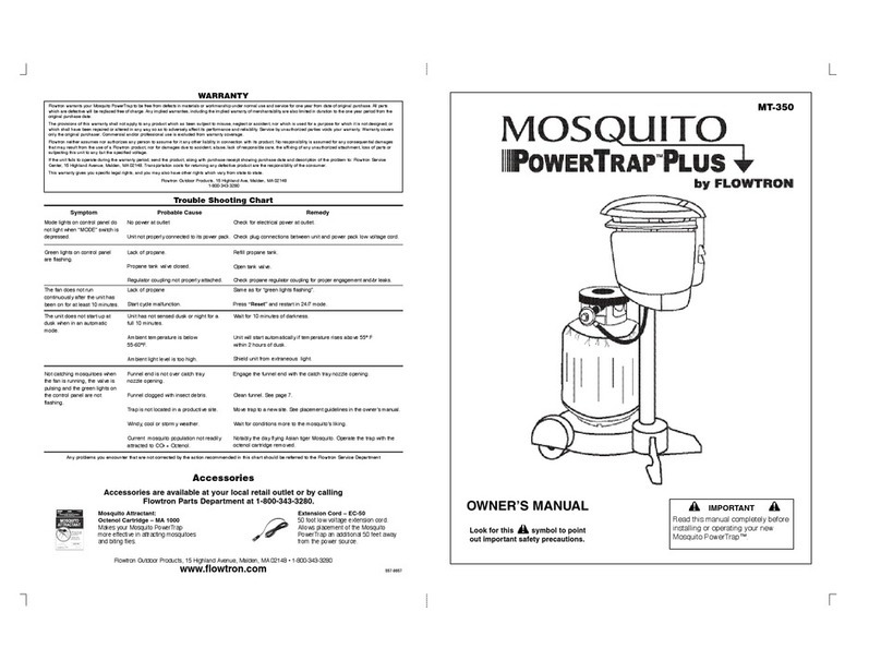
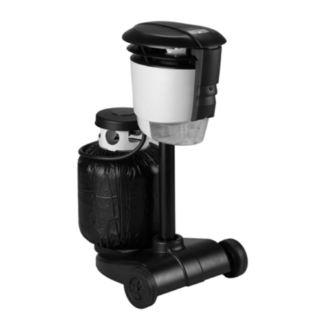
Flowtron Mosquito PowerTrap MT-125 User manual

TECHNICAL
MANUAL

FLOWTRON Outdoor Products, 15 Highland Ave., Malden, MA 02148 •
www.flowtron.com
TABLE OF CONTENTS
1 . MT-125: Abnormal Operation - Warning Signals
2. MT-125: Troubleshooting and Repair Analysis
3. MT-275: Abnormal Operation —Warning Signals
4. MT-275: Troubleshooting and Repair Analysis
5. Printed Circuit Board - Replacement
6. Motor and Fan - Replacement
7. Burner Assembly - Replacement —prior 201 1
8. Burner Assembly - Replacement —201 1 to present
Appendix:
A. Removal of Top Cover
B. Microprocessor - Replacement
C. Start-Up Characteristics
D. MT-125: Electrical Schematic
E. MT-275: Electrical Schematic
1. ABNORMAL OPERATION - WARNING SIGNALS
MT-125:
Symptom:
Flashing red LED light

Cause:
1. Lack of propane gas
a). Refill propane tank
b). Check for leaks
c). Reset the microprocessor by interrupting the unit's electrical power
d). Re-apply power to restart the unit
2. Initial start-up was unsuccessful
a). Follow "Troubleshooting and Repair Analysis" on next page to determine
cause and recommended corrective action
3. PowerTrap shut down for no apparent reason
a) Follow "Troubleshooting and Repair Analysis" on next page to determine
cause and recommended corrective action
Symptom:
Flashing blue LED light
Cause:
1. Unit experienced an overheat condition
a). Reset the microprocessor by interrupting the unit's electrical power
b). Allow unit to cool
c). Re-apply power to restart the unit
d). If condition reoccurs, follow"Troubleshooting and Repair Analysis" on next
page to determine cause and recommended corrective action
Symptom:
Not catching mosquitoes
Cause:
1. Funnel clogged or not centered over catch tray opening
a). Remove catch tray and funnel
b). Clean funnel and reinstall
c). Reinstall catch tray. Ensure that the funnel end is lined-up with the catch
tray opening
2. Trap is not located in a productive location
a). Move trap to a new site
b). Follow placement guidelines provided with the PowerTrap
3. Current mosquito species not attracted to Octenol lure
a). Operate the trap with the Octenol cartridge removed
2. MT-125 TROUBLESHOOTING AND REPAIR ANALYSIS
The following instruments are required for proper troubleshooting:
1. Multimeter
2. Thermocouple reader with hook-type test leads.
Remove top cover. Connect thermocouple test leads to pins on front end of printed circuit board.
(See appendix A for instructions on removing the top cover.)
The thermocouple reader should show ambient (room) temperature. If it shows a minus, or
negative, reading, switch the thermocouple test leads. If it shows no reading, the thermocouple
is defective (open).

Connect the power pack to an AC outlet; connect the low voltage wire to the unit's input plug.
Turn the propane valve on the propane tank to the "on" position.
The thermocouple reader should show a gradual increase in temperature. When the
temperature reaches approximately 1950 F (900 C), the propane valve should begin to operate
as verified by an audible clicking sound.
In the event the temperature does not increase, check the heater circuit using the
multimeter. A 12 volt AC reading should be present at the red heater terminals. If there is
no voltage at the heater terminals, replace the printed circuit board.
If there is a voltage, disconnect one of the heater wires at its terminal and check for continuity. If
the heater circuit shows an open condition, replace the burner assembly.
The valve operates on a pulsing voltage which is difficult to detect with a multimeter. If the valve
does not produce an audible clicking sound, replace the valve. If the valve still does not produce
a clicking sound at approximately 195 0 F (900 C), replace the printed circuit board.
Once the valve begins to operate, the burner temperature will increase slowly (approximately
20 per second) to 250-270 F, (1 20 -133 C) and then will start to increase more rapidly
(approximately 50 per second).
At approximately 3500 F, (1 770 C) the fan should begin to operate and cycle "on" for a few
seconds, then "off" for 20 - 30 seconds. At 7500 (4000 C), the fan should remain on continuously.
If the fan does not come on, check for DC voltage on the printed circuit board at the motor
terminals. Be sure to observe the correct polarity. Continue checking for motor voltage over a
period of time sufficient to allow for several motor "on/off" cycles to have occurred. If the DC
voltage is present, replace the motor. If not present, replace the printed circuit board.

In the unlikely event that the burner temperature reaches 1360 F, (7380 C), the unit will
automatically shut down and the blue LED lights will flash signaling an overheat condition. Allow
the unit to cool and then restart. If the overheat condition reoccurs, replace the propane valve.
During start-up, if the red LED light flashes, this indicates that the burner temperature will not
increase above 760 degrees. If this should occur, disconnect electrical power and allow the unit
to cool. Then restart by applying electrical power. If the condition reoccurs, replace the burner
chamber.

3. ABNORMAL OPERATION -WARNING SIGNALS
MT-275
Symptom:
Three flashing mode lights on the control panel
Cause:
1 . Lack of propane gas
a). Refill propane tank
b). Check for leaks
c). Press "off/reset" button on the control panel
d). Select mode and restart the unit
2. Initial start-up was unsuccessful
a). Follow "Troubleshooting and Repair Analysis" on next page to determine
cause and recommended corrective action
3. PowerTrap shut down for no apparent reason
a) Follow "Troubleshooting and Repair Analysis" on next page to determine
cause and recommended corrective action
Symptom:
Two flashing mode lights on the control panel
Cause:
1 . Unit experienced an overheat condition
a). Push "off/reset" button on the control panel
b). Allow unit to cool
c). Select mode and restart the unit
d). If condition reoccurs, follow"Troubleshooting and Repair Analysis" on next
page to determine cause and recommended corrective action.
Symptom:
Not catching mosquitoes
Cause:
1. Funnel clogged or not centered over catch tray opening
a). Remove catch tray and funnel
b). Clean funnel and reinstall
c). Reinstall catch tray. Ensure that the funnel end is lined-up with the catch
tray opening.
2.Trap is not located in a productive location
a). Move trap to a new site.
b). Follow placement guidelines provided with the PowerTrap
3.Current mosquito species not attracted to Octenol lure
a). Operate the trap with the Octenol cartridge removed
4. MT-275 TROUBLESHOOTING AND REPAIR ANALYSIS
The following instruments are required for proper troubleshooting:
1.Multimeter
2.Thermocouple reader with hook-type test leads.

Remove top cover. Connect thermocouple test leads to pins on front end of printed circuit board.
(See appendix A for instructions on removing the top cover.)
The thermocouple reader should show ambient (room) temperature. If it shows a minus, or
negative, reading, switch the thermocouple test leads. If it shows no reading, the thermocouple
is defective (open). Connect the power pack to an AC outlet; connect the low voltage wire to the
unit's input plug. Turn
the propane valve on.
Plug the ribbon wire extending from the underside of the top cover into the PCB and select the
24/7 mode on the control panel.
The thermocouple reader should show a gradual, steady increase in temperature. When the
temperature reaches approximately 1950F (900C), the propane valve should begin to operate as
verified by an audible clicking sound.
In the event the temperature does not increase, check the heater circuit using the multimeter. A
12 volt AC reading should be present at the red heater terminals. If there is no voltage at the
heater terminals, replace the printed circuit board.
If there is a voltage, disconnect one of the heater wires at its terminal and check for continuity.
If the heater circuit shows an open condition, replace the burner assembly.
The valve operates on a pulsing voltage which is difficult to detect with a multimeter. If the valve
does not produce an audible clicking sound, replace the valve. If the valve still does not produce
a clicking sound at approximately 1950F (900C), replace the printed circuit board.

Once the valve begins to operate, the burner temperature will increase slowly (approximately 10
- 20 per second) to 250 0-270 0 F, (1 20 0-133 0 C) and then will start to increase more rapidly
(approximately 3 0-40 per second).
At approximately 3500 F, (1770C) the fan should begin to operate and cycle "on" for a few
seconds, then "off" for 20 —30 seconds. At 7600 (4050C), the fan should remain on continuously.
If the fan does not come on, check for DC voltage on the printed circuit board at the motor
terminals. Be sure to observe the correct polarity. Continue checking for motor voltage over a
period of time sufficient to allow for several motor "on/off" cycles to have occurred. If the DC
voltage is present, replace the motor. If not present, replace the printed circuit board.
The burner temperature should stabilize at 10500 F, (5660 C) +/- 5%, 10 to 12 minutes after start.
In the unlikely event that the burner temperature reaches 1360 F (7380 C), the unit will
automatically shut down and two of the LED mode lights on the control panel will flash signaling
an overheat condition. Allow the unit to cool and then restart. If the overheat condition reoccurs,
replace the propane valve.
During start-up, if three of the LED mode lights on the control panel flash, this indicates that the
burner temperature will not increase above 760 degrees. If this should occur, switch the unit off
and allow it to cool. Then restart in the 24/7 mode. If the condition reoccurs, replace the burner
chamber.

5. PRINTED CIRCUIT BOARD- REPLACEMENT
1. Unplug the PowerTrap's electrical connector and disconnect the gas regulator from the
propane tank.
2. Remove the top cover. (See appendix A instructions on removing the top cover).
3. Disconnect the six wires from their connectors located along the outside edge of the PCB.
Disconnect the thermocouple connector located at the front edge of the PCB. Disconnect the
two black wires from the connectors on the back edge of the PC board. Remove the three nuts
at the top of the board and remove the PCB from the PowerTrap..
4. Install a new PCB and secure in place with the three nuts. Connect all wires as follows:
a). Red motor wire to motor terminal marked plus. Black motor wire to motor terminal
marked minus.
b). Red heater wires (2) to terminals marked heater.
c). White valve wires (2) to terminals marked valve.
d). Black AC power wires (2) to the AC terminals at the rear edge of the PCB.
e). Plug the thermocouple connector into the socket at the front edge of the PCB.
5. Model MT-275 only: Connect the ribbon wire from the underside of the top cover to the PCB
taking care to engage all slots in the plug with the corresponding pins in the socket.
6. Install the top cover by spreading the louvers at the rear of the unit to engage the boss at the
rear of the cover and secure with screw. Install the two screws in the front of the unit to secure
the top cover to the metal plate.
7. Re-attach the PowerTrap's electrical connector and attach the gas regulator to the propane
tank.
6. MOTOR AND FAN-REPLACEMENT
1. Unplug the PowerTrap and disconnect the gas regulator from the propane tank. Remove the
collection tray and the funnel.
2. Remove the top cover. (See appendix A for instructions on removing the top cover.)
3. Disconnect the two motor wires from the PCB. Remove the three nuts at the top of the board
and lift the PCB off its mounting. Feed the two motor wires down through the hole in the metal
plate (top plate) below the PCB.
4. Remove the eight screws that secure the metal channel running along the center of the top
plate. Remove the channel and, on Model MT-275 only, remove the metal strip holding the
insulation material along the side of the channel. This will expose the black impeller and
impeller housing. Remove the impeller from its housing by prying the impeller off of the motor
shaft. .

5. Remove the two screws holding the impeller housing to the top plate. These screws also hold
the motor in place and removing these screws will allow the motor to be removed from
beneath the top plate.
6. Remove the fan from the motor shaft and place it on the new motor. Make certain the fan is
located in the same place on the motor shaft as it was on the shaft of the old motor.
7. Position the new motor in place, run the motor wires through the hole in the top plate, then
fasten the motor and impeller housing to the top plate with two screws. Press the impeller
onto the motor shaft and make certain the top of the impeller is just below the top of the
impeller housing. Be certain that the impeller turns freely and does not rub on the bottom of
the housing.
8. . Install the metal channel and secure using the eight screws. Be sure the metal strip retaining
the insulation material is in place before the screws are secured. (Note: Insulation material is
not used on Model MT-1 25).
9. Connect the ribbon wire from the underside of the top cover to the PCB taking care to engage
all slots in the plug with corresponding pins in the socket. (Not applicable for Model MT-125).
10. Install the top cover by spreading the louvers at the rear of the unit to engage the
boss at the rear of the cover and secure with screw. Install the two screws in the front of the
unit to secure the top cover to the top plate.
1 1. Complete the installation by installing the funnel and the collection tray and attaching the
electrical connector and the gas regulator.
7. BURNER ASSEMBLY - REPLACEMENT
Applicable for Units Manufactured prior to 2011
1. Unplug the PowerTrap and disconnect the regulator from the propane tank.
2. Remove the top cover. (See appendix A for instructions on removing the top cover.) Unplug
the ribbon wire from the edge of the PCB and remove the top cover completely from the unit.
3. Disconnect remaining wires from the outside edge of the PCB. Twist off the red and yellow
thermocouple wires from the posts located at the front edge of the PCB and disconnect the
two black wires from the back edge of the board. Remove the three nuts at the top of the
board.
4. Remove the eight screws that secure the metal channel running along the center of the top
metal plate and remove the channel (and metal strip holding the insulation material along the
side). Remove the screw in the center of the top plate which secures the top plate to the
vertical rod extending through the center of the housing. Bend the tabs (two) at the top of the
burner assembly so that they are in line with the slots in the top plate.
5. Disconnect the copper tube from the valve located at the bottom of the burner assembly using
a 3/8" wrench.
6. Lift the top plate off the trap housing. Remove the burner assembly by moving it to the rear
until tabs line up with the slots in the top plate and then pull it down while passing the burner
wires through the hole in the top plate.

7. Position the replacement burner assembly in place with its tabs penetrating the metal top
plate. Make certain that the white thermal shield at the top of the burner lies under the burner
opening in the metal top plate. Bend the tabs at the top of the burner assembly outward to
hold it in place.
8. Run all wires through the hole in the top plate below the PCB while lowering the top plate
onto the trap housing. Install the screw in the center of the top plate which secures the top
plate to the vertical rod. Install the metal channel and secure using the eight screws. Be sure
the metal strip retaining the insulation material is in place before the screws are secured.
(Note: Insulation material not present on model MT-125).
9. Fasten the PCB in place with three nuts and connect the wires to the PCB as follows:
a). Red motor wire to motor terminal marked plus. Black motor wire to motor
terminal marked minus.
b). Red heater wires (2) to terminals marked heater.
c). White valve wires (2) to terminals marked valve.
d). Black AC power wires to the AC terminals at the rear edge of the PCB
e). Wrap thin red and yellow thermocouple wires securely around posts on PCB
with the red wire on post marked plus and the yellow wire on post marked
minus. Make certain these wires are wrapped tightly around their respective
posts. DO NOT SOLDER WIRES TO POST.
10. Connect the copper tube to the valve at the bottom of the burner.
1 1. Connect the ribbon wire from the underside of the top cover to the PCB taking care to engage
all slots in the plug with corresponding pins in the socket. (Not applicable for MT-1 25).
12. Install the top cover by spreading the louvers at the rear of the unit to engage the boss at
the rear of the cover and secure with screw. Install the two screws in the front of the unit to
secure the top cover to the metal plate.
13. Attach electrical plug and gas regulator. Open propane valve on tank, press off/reset button
on switch panel and set mode to 24/7. Unit should start and run in 7-10 minutes as
evidenced by the fan running continuously and the LED lights inside the unit remaining on.

8. BURNER ASSEMBLY - REPLACEMENT
Applicable for units manufactured from 2011 to present
1. Unplug the PowerTrap and disconnect the regulator from the propane tank.
2. Remove the top cover. (See Appendix A for instructions on removing the top cover.)
3. Remove the catch tray and funnel from the unit.
4. Note that the power cord is secured to the PowerTrap housing through a strain relief molded
into the housing. Detach the power cord from the strain relief by gently pulling the power
cord out through the tabs on the strain relief.
5. Remove the Phillips screw at the rear of the unit which secures the louvers to the housing.
Remove the Phillips screw at the front of the unit which secures the plenum to the housing
and remove the plenum.
6. Remove the Phillips screw located inside the recess for the mounting post located at the
bottom of the housing, then separate the housing from the louver assembly.
7. Disconnect the connector for the valve wires and the connector for the heater wires, both
located at the bottom of the burner assembly.
8. Hold the valve in place with pliers or vise grips and using a 13mm open end wrench, disconnect
the regulator hose from the valve. Make certain that the valve does not turn and stays in
position during the removal of the regulator hose.
9. Unscrew the two plastic wing nuts that secure the burner assembly to the top metal plate and
remove the burner assembly from the unit.
10. Install the replacement burner assembly and reassemble the unit by reversing the steps taken
to remove the original burner assembly.
APPENDEX

A.
REMOVAL OF TOP COVER
TO REMOVE THE TOP COVER FROM THE POWERTRAP, PROCEED AS FOLLOWS:
1 . Unplug the PowerTrap and disconnect the gas regulator from the propane tank.
2. Remove the two screws which secure the top cover to the metal plate located under the
top cover at the front edge of the unit, to the left and right of center.
3. Remove the screw used to secure the louver halves together and which captures the top
cover between the louver halves. This screw is located at the rear, center, of the unit
directly below the top cover.
4. Using a screw driver, spread the louvers and lift the back of the top cover to disengage it
from the louvers.
5. Model MT-275 only: Unplug the ribbon wire, attached to the underside of the top cover,
from the printed circuit board.
6. Remove the top cover completely from the unit.

B.
MICROPROCESSOR - REPLACEMENT
1 . Unplug the PowerTrap and disconnect the regulator from the propane tank.
2. Remove the top cover. (See Appendix A for instructions on removing the top cover.) as
follows:
3. Remove the three nuts located at the top of the PCB and raise the board to gain access to the
microprocessor.
4. Locate the microprocessors (Chip) on the PCB near the inside edge of the board and
carefully remove it from its socket.
5. Orient the replacement Chip, marked MT-125-P03 or MT-275-P04, depending upon the
applicable PowerTrap model, by matching the dimple centered at the top, left hand edge of
the Chip with the slot centered along the side of the socket and insert the Chip into the
socket.
6. Lower the PCB back into position and secure with the three nuts.
7. MT-275 only, connect the ribbon wire from the underside of the top cover to the PCB taking
care to engage all slots in the plug with corresponding pins in the socket. (Not applicable for
MT-125).
8. Install the top cover by spreading the louvers at the rear of the unit to engage the boss at the
rear of the cover and secure with screw. Install the two screws in the front of the unit to
secure the top cover to the metal plate.
9. Attach electrical plug and gas regulator.
MT-125 & MT-275

C.
Function
Elapsed Time
Temperature
Comments
Srart
0:00
25 C Ambient
Valve Pulses
88 - 93 c
Valve makes clicking sound;Gas flow
starts
Fan Starts
2:30 - 3:00 min.
170- 180 c
"On" 1 second every 20 - 30 seconds
Fan Intermittent
230 - 235 c
"On" 2 second every 20 - 30 seconds
Fan Intermittent
285 - 290 c
"On" 3 second every 20 - 30 seconds
Fan Intermittent
340 - 345 c
"On" 4 second every 20 - 30 seconds

D.
PowerTrap Start-Up Characteristics (Temperature —
Fahrenheit)
Function
Elapsed Time
Temperature
Comments
Srart
0:00
78 F Ambient
Valve Pulses
1 -2:10
190 - F
Valve makes clicking sound;Gas flow
starts
Fan Starts
2:30 - 3:00 min.
345 - 355 F
"On" 1 second every 20 - 30 seconds
Fan Intermittent
445 —455 F
"On" 2 second every 20 - 30 seconds
Fan Intermittent
545 - 555 F
"On" 3 second every 20 - 30 seconds
Fan Intermittent
645 - 655 F
"On" 4 second every 20 - 30 seconds
Fan Continuous
5:00 —8:00 min.
755 - 765 F
Auto control begins
Start-up Complete
10:00 —12:00 min
1040 - 1100 F
Stablizes at normal operating temperature
PowerTrap Start-Up Characteristics
(Temperature —Celsius)
Fan Continuous
5:00 —8:00 min.
398 —405 C
Auto control begins
Start-up Complete
10:00 —12:00
min
560 - 593 c
Stabilizes at normal operating temperature


Other manuals for Mosquito PowerTrap MT-125
1
This manual suits for next models
1
Table of contents
Other Flowtron Lawn And Garden Equipment manuals
Flowtron
Flowtron Mosquito PowerTrap MT-200 Series User manual

Flowtron
Flowtron Leaf Eater LE-800B User manual

Flowtron
Flowtron BK-15D Installation instructions

Flowtron
Flowtron Leaf Eater LE-900F User manual

Flowtron
Flowtron PV-75A Installation and operating instructions

Flowtron
Flowtron Galaxie Power-Vac PV-440A User manual

Flowtron
Flowtron 629601510101 User manual

Flowtron
Flowtron POWERTRAP MT-350 User manual
Flowtron
Flowtron BK-7 Installation and operating instructions

Flowtron
Flowtron Mosquito PowerTrap MT-125 User manual