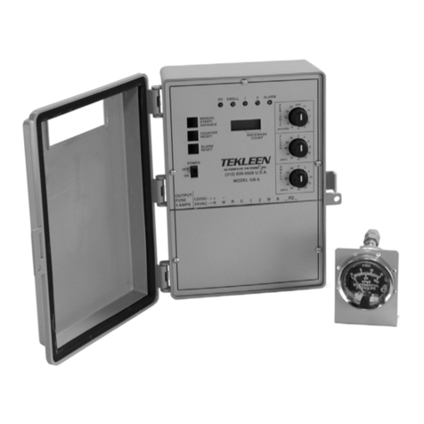
FLTR Tekleen GB6-B User manual

I

Check List for Optimal Filter Performance
☐There should be no back-pressure on the flush line. A 1” valve should
have a 2” waste line, and 1.5" and 2” valve should have a 3” waste line. Do
not use rubber hosing or flexible tubing for the waste line.
☐The differential pressure gauge should be mounted within 3 feet of the
filter. Long tubing lines will result in faulty gauge readings.
☐The water supply line to the piston should be connected to the neck of the
flush outlet and filtered by a ¼” mini filter.
☐The fitting on the side of all pistons is for venting only. It should be open
to atmospheric pressure and pointing toward the ground.
☐Sealant should be applied on the contact points on the backside of the d/p
gauge to protect it from water. The d/p gauge should be mounted such that
the blue fitting is closest to the ground to prevent shorting of the contact
points in the event of a water leak.
☐If the filter outlet discharges to a tank, or to open atmosphere, a valve
should be installed at the filter outlet to maintain a minimum working
pressure of 40 PSI during the cleaning cycle.
☐If the flush valve fails to open or close, verify the connections to the
controller are wired correctly (see diagram on pg. 15).
☐A surge protector should be installed before the electronic controller.
☐It is recommended that a pressure gauge be installed on the inlet of the
filter.
☐The filter should be oriented so that the unfiltered media source is directed
to the inlet, the manifold closest to the cover. The outlet, the manifold
closest to the flush line is the source of filtered media.
For more information:

TABLE OF CONTENTS
SECTION I: INTRODUCTION 1
SECTION II: INSTALLATION 1
SECTION III: HEADER SETTINGS 1
SECTION IV: FRONT PANEL CONTROLS & SETTINGS 2
4.1 Status Screen 3
4.2 PD Set Point 3
4.3 Backwash Time 3
4.4 Dwell Time 3
4.5 Periodic Time 4
4.6 PD Delay Time 4
4.7 Controller Configuration/Flush Cycle Counter 4
4.8 Differential Pressure Setting 5
SECTION V: USER CONNCECTIONS 5
5.1 PD 5
5.2 Valves 6
SECTION VI: GENERAL NOTES 6
6.1 Installation 6
6.2 Battery Power Supply 6
Warranty 7
For more information:

1
SECTION I: Introduction
Automatic Filters, Inc. features state of the art electronic backwash controllers in the GB
series. GB6-B controllers are complete with a differential pressure sensor, and a
backwash counter. The GB6-B controller may backwash a single filter along with a
master valve or two filters. The controller will initiate a backwash cycle in three ways:
when the differential pressure gauge is triggered, periodically by timer, or when manually
activated. They are designed for remote operation when A/C power is not readily
available.
SECTION II: Installation
GB6-B controllers come factory-prepared and are ready for use. The only steps necessary
for installation are:
1. Mounting the controller
2. Connecting the tubing and wires of the PD gauge
3. Installing the (4) AA Lithium batteries provided
4. Connecting the wires of the solenoids
Mount the electric controller on a convenient wall or panel as close as possible to the
filter to minimize the length of the pressure tubing. The pressure differential (PD)
gauge/switch is to be installed on the bottom of the controller housing with the blue
fitting closest to the ground. The ¼” tubing from the high pressure connection (red) on
the center of the PD gauge goes to the high pressure side of the filter or manifold (inlet).
The low pressure connection (blue) of the PD goes to the low pressure side of the filter or
manifold (outlet). If desired, the gauge may be removed from the housing and mounted at
a suitable location on or near the filter.
SECTION III: Header Settings
To access the header settings remove the front panel of the controller by unscrewing the
(5) screws. Please refer to Figure 1 below to see the header and jumper settings for the
controller.
NO JUMPER: Single filter configuration without a master valve.
JUMPER A-B: Single filter configuration with a master valve.
JUMPER B-C: Two filter configuration without a master valve.
Note: The 'RESET' button on the front panel must be pushed for the change to take
effect. Use a blunt object to press the button recessed under the front panel.
For more information:

Figure 1 Two Pin Jumper and Header Setting
SECTION IV: Front Panel Controls & Settings
The GB6-B has 4 push-buttons and the recessed reset button as mentioned previously.
Once the batteries are installed, the controller may be awakened by pushing and holding
any of the buttons. The controller display will go to sleep after 90 seconds of inactivity
but the controller will remain fully operational. See Figure 2 below for further details.
Figure 2 Controller Front Panel
Main
Display
Reset Button
(recessed)
Function Button
(Scrolls through
function screens)
Select Button
(Selects values
in a function)
Adjust+ Button
(Increases values)
Manual Start/Adjust-
Button
(Starts a manual
flush/Decreases values)
For more information:

4.1 Status Screen
This display shows the status of the system and the time elapsed since the last backwash.
Whenever a backwash cycle is initiated (via any of the three methods) the time elapsed is
reset and begins counting up towards the user-defined periodic time.
Note: Elapsed time will not start if periodic time is not set.
4.2 DP Set Point
Due to the use of an analog Murphy DP Gauge, there are no user defined settings on this
screen. Instead, the differential pressure set point should be set with the dial on the
Murphy DP Gauge. It is recommended that the user set this value at 7 PSI.
4.3 Backwash Time
This display allows the user to set the duration of the backwash per filter. Press SEL. and
the ADJ+ or ADJ- to set the value. It is recommended that the user set this value in a
range of 4 to 12 seconds.
4.4 Dwell Time
This setting is only available when the controller is configured for two filters. This value
determines the time between successive filter flushes. It allows the 1st filter's flush valve
to close before the 2nd filter begins flushing. Press SEL. and then ADJ+ or ADJ- to set
the value. It is recommended that the user set this value in a range of 5 to 10 seconds.
DWELL
5 SECONDS
BACKWASH TIME
10 SECONDS
SET DIFFERENTIAL
PSI ON GAUGE
BACKWASHING #1
003 SECONDS LEFT
FILTERING
00D 00H 00M 00S
System
Status
Elapsed time since
last backwash
Backwash Display
For more information:

4.5 Periodic Time
This display allows the user to set the amount of time the controller will wait after any
flush to start a periodic flush. Press SEL. and then ADJ+ or ADJ- to set the value. When
set to 0, periodic flushing is disabled.
4.6 PD Delay Time
This display allows the user to set the time that a high DP must be consistently present
before the controller initiates a flush cycle. This prevents intermittent pressure surges or
false readings from causing unnecessary flushes. Press SEL. and then ADJ+ or ADJ- to
set the value. It is recommended that the user set this value in a range of 3 to 5 seconds.
4.7 Controller Configuration/Flush Cycle Counter
This display will reflect the Header Setting initiated in Section III above and the number
of flush cycles that have occurred. To reset the counter press SEL., then SEL. again to
select 'Y', and finally MAN. to clear the count.
CLEAR COUNT Y N
000000 CYCLES
TWO STATIONS
000000 CYCLES
ONE STN + MASTER
000000 CYCLES
ONE STATION
000000 CYCLES
PD DELAY
05 SECONDS
PERIODIC
00D 00H 00M
Displayed when Jumper
is not installed.
Displayed when Jumper
is installed across A-B.
Displayed when Jumper
is installed across B-C.
For more information:

4.8 Differential Pressure Setting
This display allows the user to set the mode of DP detection. The GB6-B uses a Murphy
PD Gauge and should be left on this setting.
SECTION V: User Connections
The GB6-B has a row of connections set behind the controller front panel. See Figure 3
below for further details on connecting the PD gauge and solenoids.
Figure 3 User Connection Terminals
5.1 PD
These are the terminals for the PD gauge. Polarity is not important. The gauge should be
mounted such that the blue fitting is closest to the ground to prevent shorting of the
contact points in the event of a water leak. You may cover the contact points with
silicone or any water sealant to prevent shorting.
*PD GAUGE
SENSOR
For more information:

5.2 VALVES
The GB6-B is only compatible with two-wire latching solenoids. The negative (typically
black) wire on the solenoid(s) should be connected to terminal C. The positive (typically
red) wire on the solenoid(s) should be connected to the corresponding terminal(s) (1, 1
and M, or 1 and 2).
SECTION VI: GENERAL NOTES
6.1 Installation
The controller may be installed any desirable distance from the filter(s) granted the
DP Gauge is installed near the filter. The tubing running from the DP Gauge and the
Filter header should not exceed 3 ft.
The inside of the controller should be kept free of moisture and loose debris to
prevent shorting out the terminals.
6.2 Battery Power Supply
Under normal operating conditions the GB6-B's batteries will last for approximately
10,000 actuations of a latching solenoid. Ambient temperature, environmental factors,
and battery quality can affect this approximation. All batteries should be replaced at the
same time and should be identical to each other. Do NOT use different battery types
together. 'Energizer L91-FRG' Lithium batteries are recommended but alkaline batteries
may be used for reduced cycle count applications. It is recommend that batteries be
replaced annually to prevent unexpected usage disruptions.
Note: Changing the batteries or pressing the reset button will clear backwash cycle
counter and user settings.
For more information:

For more information:
Table of contents
Other FLTR Controllers manuals
Popular Controllers manuals by other brands

Vishay
Vishay G4 Technical manual

schmersal
schmersal AZ/AZM 415 Mounting instructions

Advanced Electronic Applications
Advanced Electronic Applications PAKRATT PK-232 operating manual

Fairford
Fairford agility Series user manual

Grundfos
Grundfos RSI Installation and operating instructions

KDE Direct
KDE Direct KDECAN Protocol KDE-UAS125UVC-HE manual