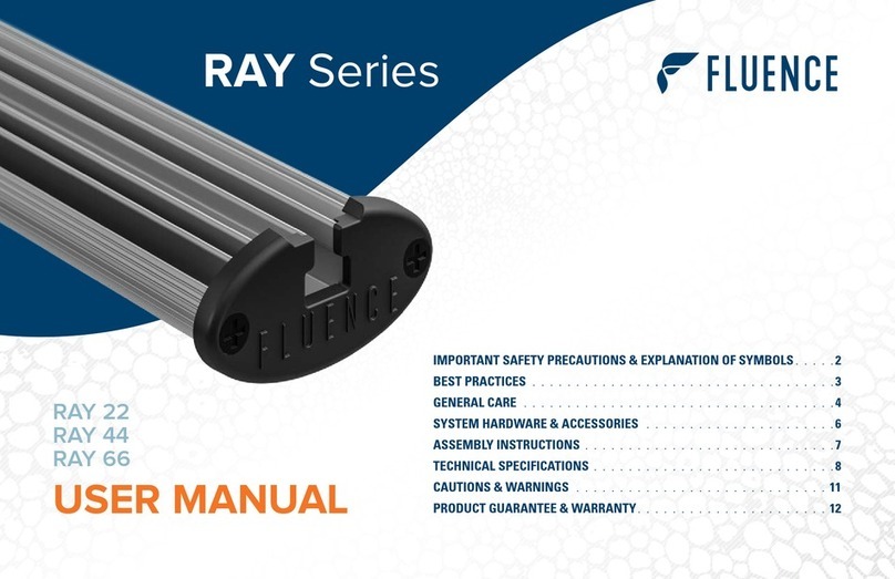
FLUENCE RAY Series User manual

RAY 22
RAY 44
RAY 66
IMPORTANT SAFETY PRECAUTIONS . . . . . . . . . . . . . . . . . . . . . . . 2
BEST PRACTICES . . . . . . . . . . . . . . . . . . . . . . . . . . . . . . . . . . . 2
GENERAL CARE . . . . . . . . . . . . . . . . . . . . . . . . . . . . . . . . . . . . 2
SYSTEM HARDWARE & ACCESSORIES . . . . . . . . . . . . . . . . . . . . . . 3
AC AND DC CABLE INSTALLATION . . . . . . . . . . . . . . . . . . . . . . . . . 4
ASSEMBLY INSTRUCTIONS . . . . . . . . . . . . . . . . . . . . . . . . . . . . . 6
TECHNICAL SPECIFICATIONS . . . . . . . . . . . . . . . . . . . . . . . . . . . . 7
CAUTIONS & WARNINGS . . . . . . . . . . . . . . . . . . . . . . . . . . . . . 10
PRODUCT GUARANTEE & WARRANTY. . . . . . . . . . . . . . . . . . . . . . 12
USER MANUAL
RAY Series

2
RAY is a high-performance lighting system.
Do not touch while in operation.
PLEASE RECYCLE ALL
PACKAGING MATERIAL
IMPORTANT SAFETY PRECAUTIONS
•The system should only be cleaned as directed in the Fluence’s Fixture
Cleaning Recommendations which can be downloaded from the Fluence
Support Center www.fluence.science/support-center/.
• You should seek service for your system by qualified service personnel if any
of the following occur:
1. The power-supply cord or the plug has been damaged.
2. The unit has been exposed to rain.
3. The unit exhibits a marked change in performance.
4. The unit has been dropped, or its enclosure or chassis is damaged.
CULTIVATION BEST PRACTICES
Fluence encourages everyone to experiment and pursue their own techniques.
Every crop is different and everyone has different goals. However, our internal
research has given us insight into several strategies we would like to share.
•Regularly check your plants’ growth and health. Fluence lighting systems
deliver high levels of PAR, typically more than experienced in nature.
Adjustments to H2O, CO2, RH, nutrients, and temperature are typically required.
• Mount the fixture at least 6” from the top of your canopy to ensure optimal
uniformity and consistent PPFD. The RAY Series was designed to provide
uniform light dispersion and requires precise deployment. A 1” variation in
either direction will have a significant change in uniformity and PPFD (which
may or may not be desired).
• Many plants prefer higher temperatures when exposed to high PPFD.
Experiment with higher temperatures to achieve higher yields. Canopy
temperature and room ambient temperature often vary. For accurate results,
test at the canopy level to gauge leaf surface temperature.
For cultivation recommendations visit
www.fluence.science/science-articles/.
GENERAL CARE
RAY Series systems is passively cooled with zero moving components.
They are designed for accepted horticulture environments and years of
maintenance-free performance. Some basic care will keep your system
operating at peak performance cycle-after-cycle.
•Natural convection removes heat away from the heatsink. In order for
the system to properly cool itself, at least one inch of space is required
between the console and the roof of your grow area. Failure to do so may
shorten the fixture’s lifespan.
• To achieve the optimal lifespan and performance of your fixtures, routinely
check for and remove excess dust, debris, and mineral build up from
heatsink and LED array. Cleaning should always be done with the fixture
unplugged from its power source using low-pressure compressed air or
water to rinse away dirt from light bars.
• Never use a cloth to clean the diode array. Doing so can scratch or
compromise the integrity of the silicon seal, or dislodge diodes entirely.
• To limit degradation, avoid touching the diodes with your hands, even in a
powered off state.
For detailed instructions for maintenance and cleaning,
please visit www.fluence.science/support-center/.

3
Mounting Hardware
Mounting Hardware
Mounting Hardware
SYSTEM HARDWARE & ACCESSORIES
SYSTEM HARDWARE
ARAY fixture pre-configured with:
A1 8’ Cord with Male DC Connector
BPower Supply pre-configured with:
B1 14” Cord with Male AC Connector
B2 13.5” Cord with Female DC Connector
B3 13.5” Cord with 3-Pin Waterproof Dimming
Connector and Dust Cap (dimmer sold separately)
B4 Pigtail Dimming Adapter (purple/gray leads)
ACCESSORIES
C Mounting Hardware
(depending on your selection at the time of purchase)
C1 (2x) Standard top-light mounting brackets
C2 (1x) 6’ AC cable
(15’ cable option if upgraded at time of purchase)
A
C
C1 C2
A1
B
B1 B3
B4
B2

4
AC AND DC CABLE INSTALLATION
WARNING: Risk of Electrical Shock. Turn off and disconnect the power before installing, moving, or cleaning to reduce the possibility of
serious injury. DO NOT connect or disconnect cables to or from the power supply or LED light bar while energized. Test all cable connections
for correct and secure engagement after installation.
INSTALLATION OF THE DC POWER CABLE TO THE LED LIGHT BAR
The DC cable use a screw-lock type M19 2-pin connector to connect the power supply to the LED light bar.
To Attach or Remove the Connectors:
To attach the connector, match up the keyed pins on the cable (male to female) to the receptacle and push it on. Twist the locking ring on the connector
clockwise to tighten until hand-tight. Check that the connector is securely attached by lightly tugging on the cable. The cable will not come off if properly
installed. Failure to test the cable connection may result in electrical shock or damage to the product.
To remove the connector, twist the ring on the base of the connector counter-clockwise until loose, and then pull straight out.
1
2
1a 1b 2a 2b
SCREW-LOCK (THREADED) CONNECTOR INSTALLATION

5
AC AND DC CABLE INSTALLATION
The AC power cable uses a screw-lock type M19 3-pin connector to connect the cable to the power supply. The connection to power is available in
several plug types for receptacles, or in pigtails for direct wiring.
To Attach or Remove the Connectors:
To install the connector, match up the keyed pins on the cable (male to female) to the receptacle and push it on. Twist the locking ring on the connector
clockwise to tighten until hand-tight. Check that the connector is securely attached by lightly tugging on the cable. The
cable will not come off if properly installed. Failure to test the cable connection may result in electrical shock or damage to the product.
To remove the connector, twist the ring on the base of the connector counter-clockwise until loose, and then pull straight out.
1
2
INSTALLATION OF THE AC POWER CABLE TO THE POWER SUPPLY
The DC dimming cable uses a screw-lock M16 3-pin connector to connect the cable to the power supply. To install the DC dimming cable:
Remove the dust cap from the power supply dimming port.
Match up the connector end on the cable (female) to the power supply dimming port (male) and push it on. Twist the ring on the connector clockwise to tighten
until hand-tight. Check that the connector is securely attached by lightly tugging on the cable. The cable will not come off if properly installed. Failure to test
the cable connection may result in electrical shock or damage to the product or connected lighting controller.
1
2
INSTALLATION OF THE DIMMING CABLE TO THE POWER SUPPLY

6
Take caution when
handling RAY fixtures.
Ensure the LED array does
not come in contact with
sharp objects or force that
may damage the diodes.
ASSEMBLY INSTRUCTIONS
Unbox RAY fixture and place on flush, stable surface.
To mount fixture, refer to the instructions included in the hanging
kit package with the associated accessories. Hang the fixture in the
desired location and adjust the mounting height to at least 6” above the
plant canopy.
Connect fixture to power supply using the 8’ DC cable attached to the
RAY fixture.
Mount the power supply to a wall or suitable support structure using
4mm/#8 fasteners (not included) through the mounting flange on the
sides of the power supply.
Attach 6’ (or 15’) AC cable to power supply AC connector. Finally, insert
AC plug into wall outlet.
If connecting RAY to a dimming system or controller, remove dust cap and
connect to the 3-pin waterproof dimming connector or the included pigtail
dimming adapter.
Note, leave dust cap attached to connector when not
dimming fixture.
1
2
3
4
5
6

7
TECHNICAL SPECIFICATIONS
STOCK KEEPING UNIT (SKU) CONFIGURATOR & OPTIONS
(Example SKU: R-22-I-1-06-N5-R)
PHOTON FLUX AND EFFICACY
Family Model Spectrum Input Voltage AC Cord Length AC Plug Mounting Hardware
RR RAY 222” IPhysioSpec Indoor™1120-277 VAC 06 6.0’ (1.83m) N5 NEMA 5–15P RStandard
444” GPhysioSpec Greenhouse™2120-277 VAC 15 15.0’ (4.57m) N6 NEMA 6–15P
666” AAnthoSpec™L7 NEMA L7–15P
FPfrSpec™PT Pigtails
RPrSpec™
UUvSpec™
RAY 22 RAY 44 RAY 66
Spectrum Photon Flux
(µmol/s)
AC Power
(W)
Efficacy
(µmol/J)
Photon Flux
(µmol/s)
AC Power
(W)
Efficacy
(µmol/J)
Photon Flux
(µmol/s)
AC Power
(W)
Efficacy
(µmol/J)
Indoor 93 40 2.33 185 79 2.34 278 115 2.42
Greenhouse 93 40 2.33 185 79 2.34 278 115 2.42
Antho 79 43 1.84 158 87 1.82 237 126 1.88
Pfr 81 32 2.53 162 65 2.49 243 94 2.59
Pr 91 37 2.46 182 74 2.46 273 108 2.53
UV 33 39 0.85 66 78 0.85 99 114 0.87
Photon Flux (360-780nm) | AC Power @ 277 V | Efficacy (360-780nm) @ 277 V AC

8
LIGHT BAR DIMENSIONS AND WEIGHT
Item SKU Abb. Length Width Height Weight
RAY 22 RY-2-x-x-xx-xx-R 22"
55.9 cm 2.2"
5.6 cm 1.4"
3.6 cm 1.3 lb
0.6 kg
RAY 44 RY-4-x-x-xx-xx-R 44"
111.8 cm 2.2"
5.6 cm 1.4"
3.6 cm 2.2 lb
1.0 kg
RAY 66 RY-6-x-x-xx-xx-R 66"
167.6 cm 2.2"
5.6 cm 1.4"
3.6 cm 3.1 lb
1.4 kg
RAY 22: Description Length Width Height Weight
1 120-277VAC 10.0 in
25.8 cm
1.9 in
4.9 cm
1.6 in
4.0 cm
2.2 lbs
1.0 kg
POWER SUPPLY DIMENSIONS AND WEIGHT
RAY 44: Description Length Width Height Weight
2120-277VAC 5.8 in
14.8 cm
2.4 in
6.0 cm
1.4 in
3.6 cm
1.5 lbs
0.7 kg
RAY 66: Description Length Width Height Weight
1 120-277VAC 10.0 in
25.6 cm
1.9 in
4.9 cm
1.6 in
4.0 cm
2.2 lbs
1.0 kg
DIMENSIONS`
[ POWER SUPPLY ]
Mounting Hardware
[ TOP VIEW ]
Length
8’ (2.43m)
Length
Height
Width
Mounting Hardware
2.2” (5.58 cm)
1.4”
(3.6 cm)
[ SIDE VIEW ]

9
MAXIMUM AC INPUT AMPERAGE
Spectrum AC Voltage 120 V 208 V 240 V 277 V
RAY 22
Indoor
Max AC
Input Current
0.34 A 0.20 A 0.17 A 0.15 A
Greenhouse 0.34 A 0.20 A 0.17 A 0.15 A
Antho 0.38 A 0.22 A 0.19 A 0.17 A
Pfr 0.28 A 0.16 A 0.14 A 0.13 A
Pr 0.32 A 0.19 A 0.16 A 0.14 A
UV 0.34 A 0.20 A 0.17 A 0.15 A
RAY 44
Indoor
Max AC
Input Current
0.69 A 0.40 A 0.36 A 0.32 A
Greenhouse 0.69 A 0.40 A 0.36 A 0.32 A
Antho 0.76 A 0.45 A 0.39 A 0.36 A
Pfr 0.57 A 0.33 A 0.30 A 0.27 A
Pr 0.64 A 0.38 A 0.33 A 0.30 A
UV 0.68 A 0.40 A 0.35 A 0.32 A
RAY 66
Indoor
Max AC
Input Current
1.02 A 0.59 A 0.50 A 0.44 A
Greenhouse 1.02 A 0.59 A 0.50 A 0.45 A
Antho 1.12 A 0.65 A 0.56 A 0.49 A
Pfr 0.84 A 0.49 A 0.42 A 0.37 A
Pr 0.96 A 0.55 A 0.47 A 0.42 A
UV 1.01 A 0.58 A 0.50 A 0.44A

10
WARNING
Turn off and disconnect the power before installation. Installation should be performed by a qualified electrician in accordance with all national and
local electrical and construction codes and regulations.
• DO NOT attempt to install or use this product until you have fully read and understand the installation instructions contained in this user and
installation guide and on the product safety labels. Failure to follow the Fluence product instructions and safety label advice may result in damage
to the product, damage to property, or personal injury. Be sure to retain a copy of this user guide after installation for future reference.
• Risk of Electrical Shock. Turn off and disconnect the power before installing, moving, or cleaning to reduce the possibility of serious injury. DO
NOT disconnect cables from the power supply or LED light bar while energized.
• Only connect the system to an electrical outlet or circuit of appropriate type and rating for the cord and plug. Connect the system only to power
sources of the correct voltages and frequencies listed in the product specifications.
• Protect power cables from being pinched, walked on, or otherwise damaged.
• Use a strain-relief or power cord grip if needed. Maintain a minimum of 1” (2.5 cm) bend radius for all cables.
• Use IP wet-rated junction boxes and fittings for the power cords equal to the IP rating of the rating of the lighting system for the application.
• DO NOT connect to live power until installation is complete and all connections are made.
• DO NOT modify or alter the product; doing so will void the warranty. Please refer to the Fluence Terms and Conditions and Limited Warranty for
further details.
• LED and heatsink surfaces may be hot. DO NOT touch while in operation. Allow sufficient cooling time before handling.
• To reduce the risk of overheating or fire, never place operating fixtures face down on a flush surface. Always allow for adequate ventilation of fixtures and
power supplies.
CAUTIONS & WARNINGS

11
CHEMICAL EXPOSURE PRECAUTION
Fluence lighting systems are designed to be resilient against crop protection products. Many chemicals used in the Commercial Horticultural
Industry are corrosive to electronic equipment. If the luminaire is accidentally exposed to a corrosive liquid or vapor (e.g. VOC –Volatile Organic
Compound and H2S – Hydrogen Sulfide) the luminaire must be rinsed with clean water as soon as possible. The product warranty will no longer
apply if the product is exposed or remains in the corrosive environment. It is recommended the luminaires be removed and protected from the
corrosive environment during all periods of disinfection or sanitization of the facility.
CALIFORNIA PROPOSITION 65 WARNING
WARNING: This product contains chemicals known to the State of California to cause cancer and birth defects or other reproductive harm. For more
information: www.P65Warnings.ca.gov.
PHOTOBIOLOGICAL HAZARD
To prevent eye damage, avoid looking directly at the unshielded LEDs. Practice safety precautions recommended by (IEC 62471 and IEC TR 62778) for
photobiological Risk Group 1.
CAUTIONS & WARNINGS
ETL Rating: RAY fixtures are rated suitable for damp locations. A “damp location” is defined as an interior or exterior location in which
water or other liquids may drip, splash or flow on or against the electrical components of a lighting fixture or ceiling fan. RAY22, RAY44
& RAY66 are certified to meet UL standards (ETL) from the Intertek safety consulting and certification company and are cETL listed.
1 PPF calculations compiled using integrating sphere measurements and typical spectroadiometric data for each LED to determine typical fixture performance. Actual photometric results may vary
within the LED manufacturer’s bin tolerance.
2 Wattage values are typical expected values. Fluence maintains a tolerance of ±10% on flux and power specifications. Target light levels can vary from projected levels depending on ambient
temperature, room reflections values and dirt accumulation.

12
fluence.science
© Copyright 2023. Fluence Bioengineering, Inc.
062023 • 70334E
Review our products, share your grow and stay
abreast of the latest Fluence news and product
releases through the channels below:
OUR PRODUCT GUARANTEE & WARRANTY
Every RAY series system is engineered and built by Fluence
Bioengineering using state-of-the-art robotics and hand
craftsmanship. RAY series systems are guaranteed against
manufacturing defects for five years from date of purchase.
Contact us at support@fluence-led.com for more warranty
information.
We stand behind our research, we stand behind our technology
and we stand behind our clients. fluence.science/warranty/
Other manuals for RAY Series
1
This manual suits for next models
3
Table of contents
Other FLUENCE Lighting Equipment manuals
Popular Lighting Equipment manuals by other brands
Miboxer
Miboxer Mi-Light CL3-P60V12 manual
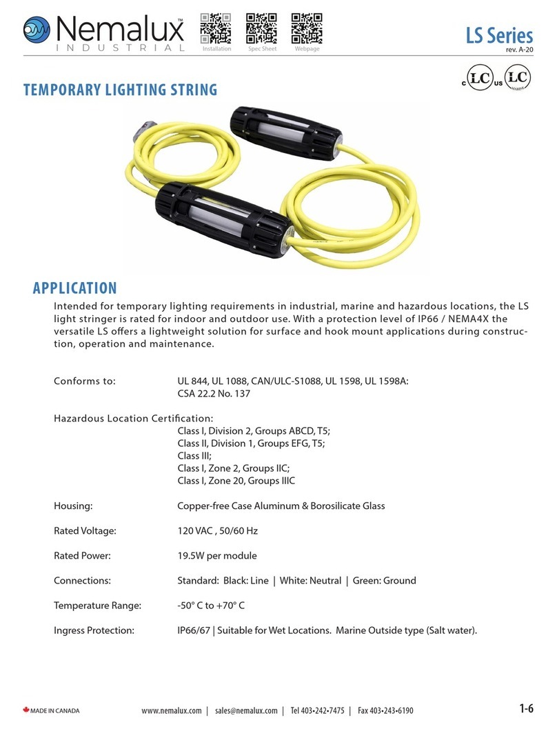
Nemalux
Nemalux LS Series manual
MADRIX
MADRIX LUNA Series Quick start guide & technical manual

Home Accents Holiday
Home Accents Holiday TY230-1614-1 Use and care guide
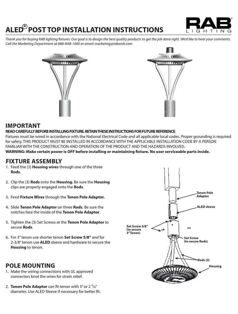
RAB Lighting
RAB Lighting ALED POST TOP installation instructions

KRAFTWERK
KRAFTWERK 24 + 5 LED instruction manual
