5
Locating the device
The choice of location for the device must meet the following condition:
• Indoors
• Ambient temperature of -10 to +40°C
• Less than 1000m above sea level
• Out of direct sunlight
• Good ventilation (see below)
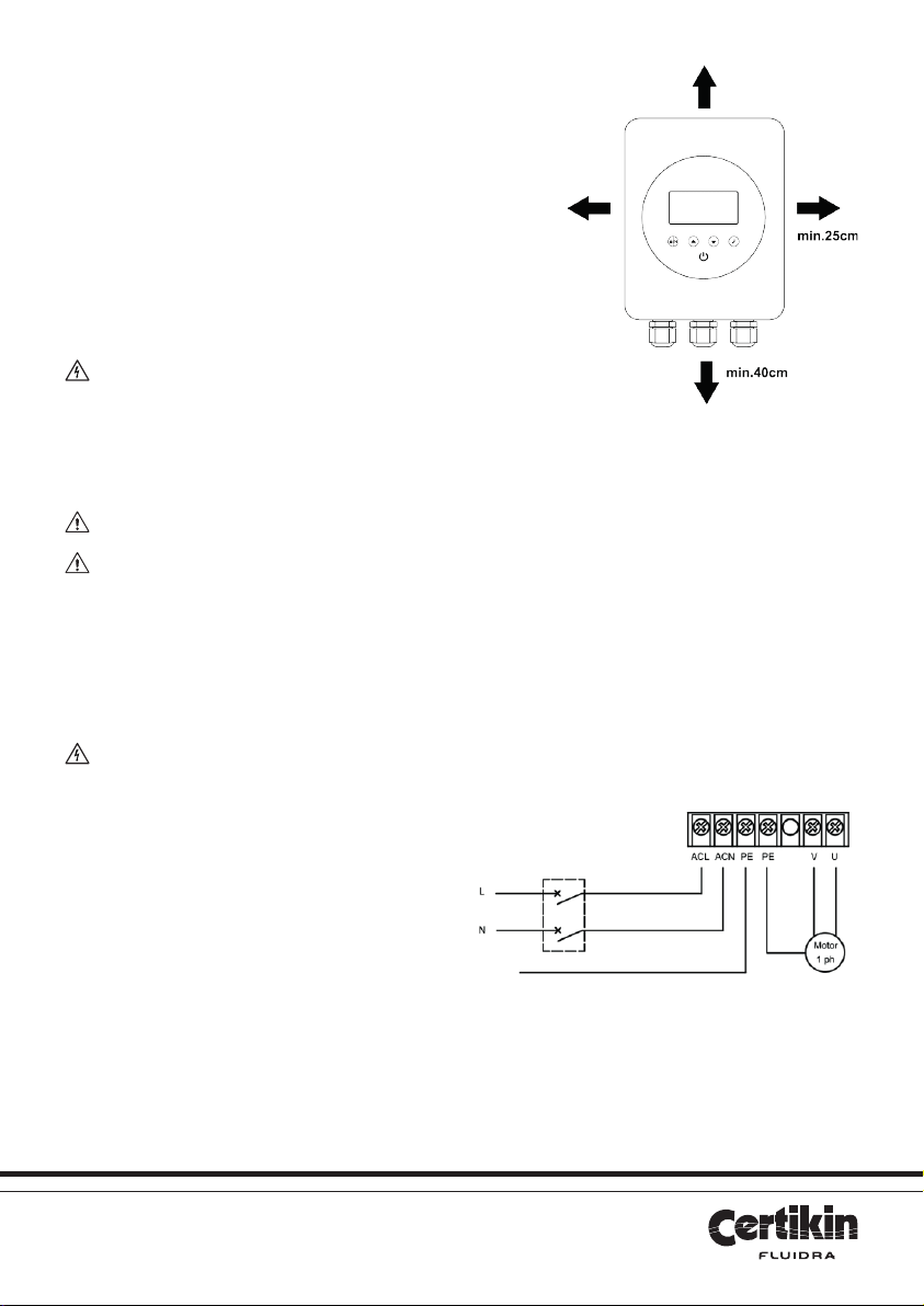
For efficient cooling, ensure the unit is installed with a minimum clearance
around it of 40cm above and below and 25cm at either side, as per Fig 2.
WARNING Blocked ventilation or an enclosed space with
limited air flow may cause overheating or potential operational failure
of the inverter.
Connecting to the pump
NOTICE Please follow these instructions for pump connection. Incorrect connection will void the warranty.
WARNING Only ONE swimming pool pump can be connected to this device – do not attempt to connect
multiple devices. Do not connect anything other than a swimming pool pump to the output of this device.
Using the template supplied, mark hole locations on the wall where the inverter is to be mounted. Drill holes and use the plugs and
fixings supplied to create the mounting position for the unit. Test mount and then remove.
From the rear of the inverter, remove the recessed screws which hold the outer cover to the body. Carefully lift and remove the outer
cover in order to gain access to the internal terminal connections.
WARNING A qualified electrician must carry out all electrical wiring in accordance with local electrical
regulations.
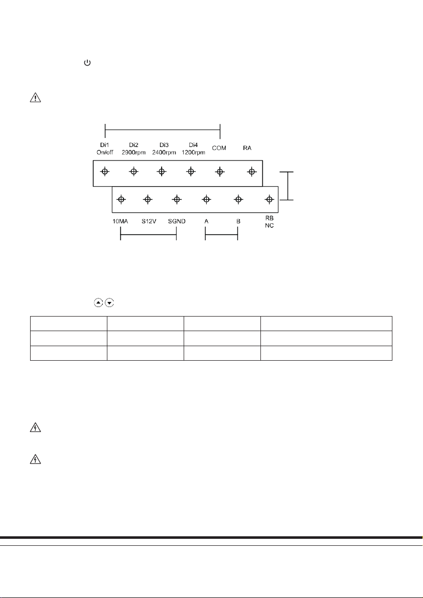
If currently installed, turn off the full electrical supply to the
swimming pool pump. Unwire the pump and make a connection,
through the cable glands, to the correct terminals within the
inverter as shown in Fig. 3. Ensure all terminal connections are
well made and tight.
Connect the pre-wired power cord from the inverter to the
power source, via and RCD with a rated residual current no
exceeding 30Ma (this will very probably be the power source
that the pump was originally connected to).
Carefully reconnect the outer cover of the inverter and mount
it onto the fixing screws. The electrical supply can now be
reinstated and the inverter is ready for use.
Fig 2: Spacing around the iSaver+ inverter
Fig 3: Terminal connections within the inverter.