Fluke 80i-2010s User manual

PN 5130594 June 2019
©2019 Fluke Corporation.
All rights reserved. Specifications are subject to change without notification.
All product names are trademarks of their respective companies.
80i-2010s
AC/DC Current Clamp
Instructions
Introduction
Use the Fluke 80i-2010s AC/DC Current Clamp (the Clamp or Product)
with oscilloscopes and digital multimeters and power analyzers for
accurate non-intrusive measurements of ac, dc, and complex waveform
currents.
Using advanced Hall Effect technology, the Clamp can accurately
measure currents up to 2000 A RMS. These features make it a powerful
tool for use in inverters, switch mode power supplies, industrial
controllers, automotive diagnostics, and other applications requiring
current measurements and/or waveform analysis.
Table 1 shows the Clamp.
How to Contact Fluke
To contact Fluke, call one of the following telephone numbers:
• Technical Support USA: 1-800-44-FLUKE (1-800-443-5853)
• Calibration/Repair USA: 1-888-99-FLUKE (1-888-993-5853)
• Canada: 1-800-36-FLUKE (1-800-363-5853)
• Europe: +31 402-675-200
• Japan: +81-3-6714-3114
• Singapore: +65-6799-5566
• China: +86-400-921-0835
• Brazil: +55-11-3530-8901
• Anywhere in the world: +1-425-446-5500
Or, visit Fluke's website at www.fluke.com
To view, print, or download the latest manual supplement, visit
http://us.fluke.com/usen/support/manuals.
Go to www.fluke.com to register your product and find more information.

Safety
A Warning identifies conditions and procedures that are dangerous to the
user.
XW Warning
To prevent possible electrical shock, fire, or personal injury:
• Read all safety information before you use the Product.
• Use the Product only as specified, or the protection
supplied by the Product can be compromised.
• Comply with local and national safety codes. Use personal
protective equipment (approved rubber gloves, face
protection, and flame-resistant clothes) to prevent shock
and arc blast injury where hazardous live conductors are
exposed.
• Do not use the Product around explosive gas, vapor, or in
damp or wet environments.
• Examine the case before you use the Product. Look for
cracks or missing plastic. Carefully look at the insulation
around the terminals.
Table 1. 80i-2010s AC/DC Current Clamp
Item Description Item Description
Tactile Barrier DJaws
Zero Adjust EBattery Cover
Fastener
ON/OFF FBattery Cover
2
3
4
1
6
5

• Use Product-approved measurement category (CAT),
voltage, and amperage rated accessories (probes, test
leads, and adapters) for all measurements.
• Do not use test leads if they are damaged. Examine the
test leads for damaged insulation and measure a known
voltage.
• Before each use, examine the Product. Look for cracks or
missing pieces of the clamp housing or output cable
insulation. Also look for loose or weakened components.
Carefully examine the insulation around the jaws.
• Hold the Product behind the tactile barrier. See of
Table 1.
• Do not use the Product if it is damaged.
• Do not use the Product if it operates incorrectly.
• The battery door must be closed and locked before you
operate the Product.
• Remove all probes, test leads, and accessories before the
battery door is opened.
• Do not work alone.
• Do not exceed the Measurement Category (CAT) rating of
the lowest rated individual component of a Product,
probe, or accessory.
• Do not touch voltages >30 V ac rms, 42 V ac peak, or
60 V dc.
• Have an approved technician repair the Product.
Table 2 shows symbols that can be used on the Product or in this
document.
Table 2. Symbols
Symbol Definition
WWARNING - RISK OF DANGER.
XWARNING. HAZARDOUS VOLTAGE. Risk of electric
shock.
Consult user documentation.
TDouble Insulated
,Application around and removal from uninsulated
hazardous live conductors is permitted.
Battery
)Certified by CSA Group to North American safety
standards.

Operating Instructions
XW Warning
To prevent possible electrical shock, fire, or personal injury:
• When using the Clamp, ensure that your fingers are
behind the protective barrier as shown in Table 1.
• Do not use the Clamp if any part, including the lead and
connector(s), appears to be damaged or if a malfunction
of the instrument is suspected.
• Before using the clamp make sure there is no dust or any
small debris on the closing faces of the jaw.
• Close the jaws gently and avoid closing them with high-
impact. The force of the impact can affect the accuracy of
the measurement.
Turn on the Clamp
Push + for 2 seconds to turn on/off the clamp.
• Green LED indicates the Clamp is ON and the battery is ok.
• Orange LED indicates the battery is lower than 2.2 V.
• Red LED indicates the battery is lower than 2 V. Replace the
battery before doing a measurement.
PConforms to European Union directives.
Conforms to relevant Australian Safety and EMC
standards.
Conforms to relevant South Korean EMC Standards.
Measurement Category III is applicable to test and
measuring circuits connected to the distribution part of
the building’s low-voltage MAINS installation.
Measurement Category IV is applicable to test and
measuring circuits connected at the source of the
building’s low-voltage MAINS installation.
~
This product complies with the WEEE Directive marking
requirements. The affixed label indicates that you must
not discard this electrical/electronic product in domestic
household waste. Product Category: With reference to
the equipment types in the WEEE Directive Annex I, this
product is classed as category 9 "Monitoring and
Control Instrumentation" product. Do not dispose of this
product as unsorted municipal waste.
Table 2. Symbols (Continued)
Symbol Definition

Zero Adjustment
The output zero offset voltage of the Clamp may change due to thermal
shifts and other environmental conditions. To adjust the output voltage to
zero:
1. Make sure that the Clamp is away from the current carrying
conductor.
2. Push Zero Adjust and wait until the power LED (+) stops flashing.
Note
The Clamp cannot do the zero adjustment if the output
voltage is ±25 mV.
Current Measurement
To measure current:
1. Turn on the Clamp and check the LED status.
2. Connect the output lead/adapter to an oscilloscope, mulitmeter,
power analyzer, or other measuring equipment.
3. If necessary, adjust the Clamp output voltage to zero as described
in the section Zero Adjustment.
4. Clamp the jaw around the conductor and make sure there is good
contact between the closing faces of the jaw.
5. Take measurements as required. Positive output indicates that the
current flow is in the direction shown by the arrow on the clamp.
Maintenance
Before each use, inspect the Clamp. Look for cracks or missing portions of
the housing and output cable insulating cover and for loose or weakened
components.
Cleaning and Storage
Periodically wipe the case with a damp cloth and detergent. Do not use
abrasives or solvents. Do not immerse the Clamp in liquids.
Battery Replacement
XW Warning
To prevent possible electrical shock, fire, or personal injury:
• Replace the batteries when the low battery indicator
shows to prevent incorrect measurements.
• Always remove the Clamp from any live electric circuit,
and make sure leads are disconnected before removing
the battery cover.
• Never operate the Clamp without the battery cover
installed.
When the clamp approaches the minimum operating voltage, the red LED
indicates the battery is low.
To replace the battery (see Figure 1):
1. Disconnect the Clamp from any conductor.
2. Turn off the Clamp.
3. Disconnect the output leads from external equipment.

4. Locate the battery cover on the handle and unlock the fastener.
5. Remove the battery door and install the new batteries (IEC LR6).
6. Replace the battery cover, and lock the fastener.
Note
Replace the battery with the specified type only. Replacing
with the wrong battery type will invalidate the warranty.
Figure 1. Battery Installation
General Specifications
Dimensions..................................... 110 mm x 270 mm x 46 mm
Weight ............................................ 710 g
Output Cable .................................. 1.5 m Shielded Coaxial cable with
BNC male connector
Maximum Conductor Diameter....... 52.0 mm
Maximum Jaw Opening.................. 81.5 mm
Output to Zero ................................ Auto adjustment with zero button
Temperature
Operating .................................... -10 °C to 50 °C
Storage (battery removed) .......... -30 °C to +60 °C
Operating Humidity ..............................≤90 % RH (at 10 °C to 30 °C)
≤75 % RH (at 30 °C to 40 °C)
≤45 % RH (at 40 °C to 50 °C)
Altitude
Operating.................................. 2000 m
Storage..................................... 12 000 m
Demagnetize Clamp......................... Open and gently close the Clamp
jaws several times
Use of the clamp on non-insulated conductors is limited to 1000 V ac
rms or dc and frequencies below 1 kHz
Safety ............................................. IEC 61010-1, Pollution Degree 2
IEC 61010-2-032: CAT III 1000 V /
CAT IV 600 V
Ingress Protection .......................... IEC 60529, IP40
1 2

Electromagnetic Compatibility (EMC)
International.............................. IEC 61326-1: Portable
Electromagnetic Environment
IEC 61326-2-2, CISPR 11: Group 1,
Class A
Group 1: Equipment has intentionally generated and/or use
conductively coupled radio-frequency energy which is necessary for
the internal functioning of the equipment itself.
Class A: Equipment is suitable for use in all establishments other
than domestic and those directly connected to a low voltage power
supply network which supplies buildings used for domestic purposes.
There may be potential difficulties in ensuring electromagnetic
compatibility in other environments, due to conducted and radiated
disturbances.
Emissions that exceed the levels required by CISPR 11 can occur
when the equipment is connected to a test object.
Korea (KCC) ................ Class A Equipment (Industrial Broadcasting &
Communication Equipment)
Class A: Equipment meets requirements for industrial
electromagnetic wave equipment and the seller or user should take
notice of it. This equipment is intended for use in business
environments and not to be used in homes.
Electrical Specifications
All accuracies stated at 23 °C ±1 °C (73.4 °F ±1.8 °F)
Current Range ............................... 2000 A ac rms, ±2000 Adc
Output Sensitivity ........................... 1 mV/A
Accuracy......................................... ±0.8 % of reading ±0.2 % of range
Bandwidth to Meet
Accuracy Specification ................... DC to 400 Hz
Load impedance............................. >1 MΩ and <10 pF
Frequency Response
(small signal) .................................. DC to 20 kHz (-3dB)
Temperature Coefficient................. Add 0.1 x specified accuracy for each
degree C above 28 °C or below 18 °C
Working Voltage ............................. 1000 V ac rms or dc
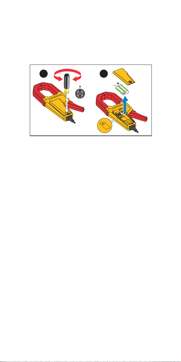
Power Supply
Type ............................................ 2x AA alkaline battery, IEC LR6
Battery Life .................................. 150 hours
Low battery indicator ................... yes

LIMITED WARRANTY AND LIMITATION OF LIABILITY
This Fluke product will be free from defects in material and workmanship
for one year from the date of purchase. This warranty does not cover
fuses, disposable batteries, or damage from accident, neglect, misuse,
alteration, contamination, or abnormal conditions of operation or handling.
Resellers are not authorized to extend any other warranty on Fluke’s
behalf. To obtain service during the warranty period, contact your nearest
Fluke authorized service center to obtain return authorization information,
then send the product to that Service Center with a description of the
problem.
THIS WARRANTY IS YOUR ONLY REMEDY. NO OTHER
WARRANTIES, SUCH AS FITNESS FOR A PARTICULAR PURPOSE,
ARE EXPRESSED OR IMPLIED. FLUKE IS NOT LIABLE FOR ANY
SPECIAL, INDIRECT, INCIDENTAL OR CONSEQUENTIAL DAMAGES
OR LOSSES, ARISING FROM
ANY CAUSE OR THEORY. Since some states or countries do not allow
the exclusion or limitation of an implied warranty or of incidental or
consequential damages, this limitation of liability may not apply to you.
11/99
Fluke Corporation
P.O. Box 9090
Everett, WA 98206-9090
U.S.A.
Fluke Europe B.V.
P.O. Box 1186
5602 BD Eindhoven
The Netherlands
Beijing Fluke
Rm101, 1/F.,Tong Heng Tower
No. 4 Hua Yuan Road Hai Dian
District, Beijing 100088, P.R.C.
Table of contents
Other Fluke Measuring Instrument manuals

Fluke
Fluke SMFT-1000 User manual

Fluke
Fluke i410 User manual

Fluke
Fluke FI-500 FiberInspector Micro User manual

Fluke
Fluke 411D User manual

Fluke
Fluke 374 FC User manual

Fluke
Fluke CPS-40M-HC40 User manual

Fluke
Fluke 35040 Operators User manual

Fluke
Fluke 941 User manual

Fluke
Fluke OptiView User manual

Fluke
Fluke 116 User manual

Fluke
Fluke FOM User manual

Fluke
Fluke 753 User manual

Fluke
Fluke 893A User manual

Fluke
Fluke 321 Use and care manual

Fluke
Fluke CableAnalyzer DTX-1500 User manual

Fluke
Fluke PRV240 User manual

Fluke
Fluke 5020AThermo-Hygrometer 5020A User manual

Fluke
Fluke 1630-2 Use and care manual

Fluke
Fluke 1587 User manual

Fluke
Fluke FS17XX User manual