Hengstler Tico 731.4 User manual

Vereinfachung
Werksseitig voreingestellt ist bereits: hohe Zählfrequenz (7,5 kHz) und
positive Flanke (HI PNP) sowie ungesperrte Fronttaste (unloc).
2. Information zum Summenzähler (0 731 401/501)
Der Applikationseingang (Klemme 7) arbeitet als GATE-Eingang, d.h
wenn dieser Eingang aktiviert wird, werden eingehende Zählimpulse
nicht gezählt.
Bei Sonderausführungen (0 731 751) wird der Transistorausgang bei
Erreichen der voreingestellten Vorwahl aktiviert.
3. Information zum Tachometer (0 731 402/502)
Der Tachometer zeigt generell die Impulse in der Einheit 1/min an. Der
Applikationseingang (Klemme 7) arbeitet als HOLD-Eingang (Anzeige-
speicher), das heißt solange ein aktives Signal (high oder low, siehe Kap
1.) am Eingang ansteht, bleibt der aktuelle Wert im Display stehen.
Reset und Transistorausgang (Klemmen 5 und 8) sind nicht belegt.
4. Information zu den Zeitzählern (403/503 und 404/504)
Der Zeitzähler zählt die Zeit, während am Zähleingang ein aktiver
Pegel anliegt, (je nach Programmierung Kap. 1, ist das entweder ein
High oder ein Low-Pegel).
Der Applikationseingang (Klemme 7) arbeitet wie beim Tacho als
Anzeigespeicher („HOLD“). Bei Sonderausführungen (0 731 753 und
754) wird der Transistorausgang bei Erreichen der voreingestellten
Zeitvorwahl aktiviert.
5. Information zur Positionsanzeige (0 731 406/506)
Die 2-kanalige Positionsanzeige ist ausgelegt für die Verarbeitung von
zwei 90° versetzten Signalen. Der Eingang COUNT A ist für den
1. Kanal des Drehimpulsgebers, Count B für den 2. Kanal. Der
Transistorausgang (Klemme 8) ist nicht belegt. Wertebereich: -99 999
bis 999 999 (LED).
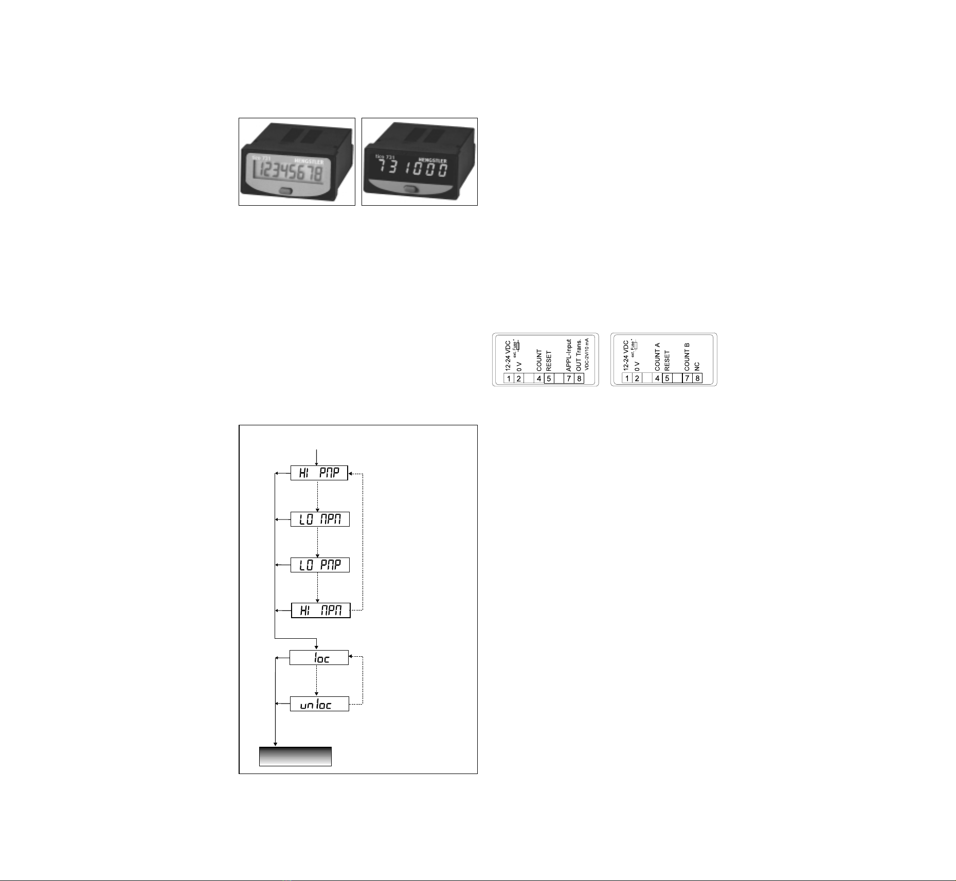
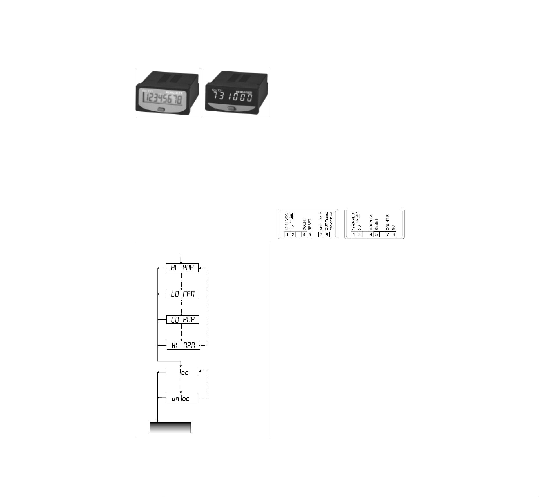
6. Klemmenbelegung
Summen-, Zeitzähler, Tacho 2-kanalige Positionsanzeige
7. Technische Daten
DC-Versorgung Klemme 1, 2: 12..24 VDC; +20/-10%
Stromaufnahme < 150 mA (LED); < 50 mA (LCD)
Überstromschutz extern:0,15 AT (LED), 0,063 AT (LCD)
Werterhaltung NV-FRAM; >10 Jahre
Anzeige LED, 6-stellig, 7,6 mm hoch
Zähleingang bei Positionsanzeige Klemmen 4 und 7
Aktive Zählflanke, pnp oder npn einstellbar siehe Kap 1.:
gültig für alle Eingänge Impulsdauer min 70 µs bzw. 15 ms
Zählfrequenz einstellbar siehe Kap 1:
Zähler, Tacho, Zeitzähler: „HI“ 7,5 kHz oder „LO“ 30 Hz (bedämpft
Positionsanzeige 2 kHz bei 90° phasenversetztem Signal
Amplitudenschwellen < 0,7 V und > 5 V, max 30 VDC
Rücksetzeingang aktive Flanke eingestellt gemäß Kap 1
(Klemme 5) und Impulsdauer: min: 15 ms, da prellsicher
Applikationseingang bedämpft auf 30 Hz
(Klemme 7)
Sperre der Fronttaste programmierbar, siehe Kap 1.
Transistor-Ausgang U max.: VDC-2V; I max.10 mA
Einbau Fronttafelmontage mit Spannrahmen
Frontabmessung DIN 48 mm x 24 mm
Einbauausschnitt 45 + 0,6 mm x 22 + 0,3 mm
Fronttafelstärke max. 26 mm
Einbautiefe 60 mm
Schutzart Frontseite IP 54
Betriebstemperatur -10° C bis +50°C
Lagertemperatur -20° C bis +60°C
Allgemeine Auslegung DIN EN 61010 Teil 1 bzw
VDE 0411 Teil 1
Schutzklasse entsprechend II
Überspannungskat. II
Verschmutzungsgrad 2
Betriebsanleitung tico 731.4 und 731.5
- Zähler mit DC-Versorgung
Die Zähler tico 731.4 und 731.5 sind Zähler für den Fronttafeleinbau
mit 12..24 VDC Spannungsversorgung für Kontakt- oder
Spannungsimpulse. Die erhältlichen Ausführungen sind:
LCD LED
Standard Sonder Standard Sonder
Summenzähler: 0731401 0731741 0731501 0731751
Tachometer (1/min): 0731402 0731742 0731502 0731752
Zeitzähler (Std:Min:Sec): 073 403 0731743 0731503 0731753
Zeitzähler (Std. 1/100 Std): 0731404 0731744 0731504 0731754
numerische SPS-Anzeige:10731405 0731745 0731505 0731755
2-kanalige Positionsanzeige: 0731406 0731746 0731506 0731756
1. Zählfrequenz, aktive Flanke und Tastatursperre
Zur optimalen Anpassung an Ihre Anwendung kann der Zähleingang
programmiert werden (30 Hz prellsicher oder schnelles Zählen), kann
die aktive Flanke gültig für Count, Reset und Appl-Eingang eingestellt
werden (positive oder negative Impulsflanke) und die Fronttaste verrie-
gelt werden.
Im Falle einer Umprogrammierung gehen Sie bitte folgendermaßen
vor:
**
*
*
ZählmodusCount Mode
Zählmodus
Zählmodus
Wert bestätigen
lang drücken (>2 sec)
Wert bestätigen
lang drücken
Erläuterung:
zählt auf die negative
Impulsflanke bei max.
7,5 kHz Zählfrequenz
Erläuterung:
zählt auf die positive
Impulsflanke bei max.
7,5 kHz Zählfrequenz
Erläuterung:
Eingang prellsicher
bedämpft auf 30 Hz und
zählt auf die negative
Impulsflanke (z.B. Kontakte)
Erläuterung:
In dieser Stellung wird die
Fronttaste gesperrt
Erläuterung:
Eingang prellsicher
bedämpft auf 30 Hz und
zählt auf die positive
Impulsflanke (z.B. Kontakte)
Erläuterung:
In dieser Stellung ist die
Fronttaste nicht gesperrt
*werksseitig voreingestellt
**entfällt bei Zeitzähler
Fronttaste gedrückt halten
und Spannung einschalten
kurz drücken
kurz drücken
kurz drücken
kurz drücken
Einstellung ändern
1Für die numerische SPS-Anzeige ist eine gesonderte Bedienungsanleitung mit Protokollbeschreibung erhältlich (Best.-Nr. 2 731 022).
Sach-Nr. 2 731 025 Version 9.98
1170709MD1
The tico 731.4 and 731.5 are panel mounted counters with 12..24 VDC
power supply and programmable input for contact or edge triggering.
The following versions are available: LCD LED
standard special standard special
Totalizer: 0731401 0731741 0731501 0731751
Tachometer (1/min): 0731402 0731742 0731502 0731752
Time counter (H:Min:Sec): 0731403 0731743 0731503 0731753
Time counter (H. 1/100 H): 0731404 0731744 0731504 0731754
numeric PLC-Display10731405 0731745 0731505 0731755
bidirectional position indicator:
0731406 0731746 0731506 0731756
1. Programming of count frequency, active edge and keylock
In order to match your application, the COUNT input frequency can be
programmed for high speed (7,5 kHz) or low speed counting (30 Hz
attenuated). Active edge for Count, Reset and Appl-Input is pro-
grammable as well as the keylock.
Note:
The counter leaves the factory with the default value HI PNP
(fmax7,5 kHz and positive edge triggered) and unlocked key.
To change the count input configuration:
2. Totalizer version (0 731 401/501)
The application input (Terminal 7) is a GATE-Input. If this Input is
active, incoming count pulses are ignored.
For special version (0 731 751): The transitor output will be activated
when the factory programmed preset value is reached.
3. Tachometer version (0 731 402/502)
The tachometer shows the the speed in 1/min. The application input
(Terminal 7) is a HOLD-Input. As long as this input is active, the actual
value in the display is frozen. Reset and transistor output are not
connected.
4. Time counter versions (0 731 403/503 and 404/504)
The time counters will count as long as the Count-Input (4) is active.
(this can be a low or a high signal according to programming in
Chapter 1). The application input (Terminal 7) is a HOLD-Input.
For special version (0 731 751): The transitor output will be activated
when the factory programmed preset value is reached.
5. Position indicator version (0 731 406/506)
The bidirectional position indicator is working with two 90° encoder
signals. COUNT A is for Channel A, COUNT B is for Channel B of the
encoder. Range: -99 999 bis 999 999 (LED).
The transstor output is not connected.
6. Terminal connections
Totalizer, Tacho, Time counters position indicator
7. Specifications
Power supply Terminal 1, 2: 12..24 VDC, +20/-10%
Current < 150 mA (LED); < 50 mA (LCD)
Overvoltage protect Ext. :0,15 AT (LED), 0,063 AT (LCD)
Data retention NV-FRAM; >10 years
Display LED, 6-digit; 7,6 mm high
LCD, 8-digit; 7 mm high
Count input All versions: terminal 4
position indicator terminal 4 and 7
Active edge valid for Programmable positve or negative see
all inputs chapter 1; puls length min 70 µs
(7,5 kHz) or 15 ms (30 Hz attenuated)
Count frequency Programmable see chapter 1:
totalizer, tacho, time „HI“ 7,5 kHz or „LO“ 30 Hz (attenuated
counters: for contacts)
Positionsanzeige 2 kHz with 90° encoder signals
Amplitude threshold < 0,7 V and > 5 V, max 30 VDC
Reset input: Active edge in accord to chapter 1
(Terminal 5) and Pulse length : min: 15 ms, because
Application input (7) 30 Hz attenuated
Keylock Programmable see chapter 1
Transistor output U max.:VDC-2V; I max.10 mA
Mounting Frontpanel with clamping frame
Front dimensions DIN 48 mm x 24 mm
Panel cut-out 45 + 0,6 mm x 22 + 0,3 mm
Panel thickness max. 26 mm
Product depth 60 mm
Protection class Frontside IP 54
Operating temperature -10° C to +50°C
Storage temperature -20° C to +60°C
General rating DIN EN 61010 part 1, VDE 0411 part 1
Protection class according to class II
Overvoltage. category II
Contamination level 2
Operating instructions tico 731.4 und 731.5
- DC-powered LCD and LED Counters
1There is an extra operating instruction (No. 2 731 022) with protocol description for the numeric PLC-display.
to confirm the desired value
to confirm the desired value
press button longer (> 2 sec)
press button longer (> 2 sec)
Note:
Maximum count speed
(7,5 kHz) and negative
edge triggered
Note:
Maximum count speed
(7,5 kHz) and positive
edge triggered
Note:
low count speed (30 Hz
attenuated) and negative
edge triggered (e.g.
contacts)
Note:
low count speed (30 Hz
attenuated) and positive
edge triggered (e.g.
contacts)
Note:
front key is locked
Note:
front key is unlocked
*default values
hold down the front key
and switch power on
press button shortly
press button shortly
press button shortly
press button shortly
to changes values
**not applicable to time counters
ZählmodusCount Mode
Zählmodus
Count Mode
**
*
*
1170709MD1

2. Informazioni riguardo i totalizzatori (0 731 401/501)
L’applicazione del circuito porta (Gate) viene attivata tramite il termi-
nale 7. Se questo ingresso è attivato , gli impulsi in arrivo non ven-
gono conteggiati.
Per la versione speciale ( 0 731 751): l’uscita a transistor verra’ attivata
quando il valore di preselezione impostato dalla fabbrica viene raggi-
unto.
3. Informazioni riguardo i tachimetri (0 731 402/502)
Il tachimetro visualizza la velocita’ (1/min.). L’applicazione di un seg-
nale al piedino 7 blocca la visualizzazione, cio’ significa che fintanto
che c’è un segnale il valore bloccato sul display rimane.
4. Informazioni riguardo i contaore (403/503 e 404 /504)
Il contaore conteggia il tempo mentre all’ingresso di conteggio (4) c’è
un segnale attivo (secondo la programmazione cap. 1 di un livello alto
oppure basso). L’applicazione di un segnale al terminale 7 blocca la
visualizzazione.
5. Indicatore di posizioni (0 731 406/506)
L’indicatore di posizione bidirezionale è predisposto per due segnali
sfasati di 90° .Segnale A a canale A, segnale B a canale B dell’encoder.
Range da -99 999 a 999 999 (LED).
L’uscita a transistor non è collegata.
6. Morsettiera
Totalizzatore, tachimetro, contaore. Indicatore di posizioni
7. Dati tecnici
Tensione di alimentazione morsetto 1 e 2; 12/24 V cc + 20% - 10%
Corrente assorbita < 150 mA (LED) < 50 mA (LCD)
Memoria dati NV-RAM > 10 anni
Display LED 6 cifre alte 7,6 mm LCD 8 cifre
alte 7 mm
Ingresso conteggio totalizzatore, tachimetro e contaore,
morsetto 4; totalizzatore bidirezionale
morsetto 4 e 7
Fronte di conteggio programmabile positivo o negativo vedi
cap. 1; segnale positivo, durata
dell’impulso min. 70 us (7,5 kHz) oppure
15 ms (30 Hz)
Frequenza di conteggio programmabile vedi cap. 1; totalizzatore,
tachimetro alta 7,5 kHz o bassa 30 Hz;
contaore per contatti
Indicatore di posizione 2 kHz segnale da encoder sfasati di 90°
Soglie d’ampiezza < 0,7 V e > 5 V max 30 V cc
Ingresso di ripristino fronte attivo vedi cap. 1; durata
(morsetto 5) e applicazione impulso min. 15 ms perchè a 30 Hz
impulso (morsetto 7) attenuati
Blocco tastiera programmabile vedi cap.1
Uscita transistor U max V cc 2 V; I max 10 mA
Montaggio pannello frontale con telaio di fissaggio
Dimensioni frontali DIN 48 mm x 24 mm
Dima di foratura 45 (+ 0,6) mm x 22 (+0,3 mm)
Spessore pannello frontale 26 mm max
Profondità prodotto 60 mm
Tipo di protezione frontale IP 54
Temperatura di esercizio - 10° C fino a + 50° C
Temperatura di stoccaggio - 20° C fino a + 60° C
Criteri costruttivi DIN EN 61010 parte 1, VDE 0411 parte 1
Classe di protezione secondo la classe II
sovratensione Categoria II
Contaminazione Grado 2
Istruzioni d’uso tico 731.4 e 731.5
- Contatori LCD e LED con alimentazione DC
I contatori TICO 731.4 e 731.5 sono contatori per montaggio da panel-
lo frontale con tensione di alimentazione 12..24V cc per ingresso
impulsi a contatto o in tensione.
I modelli disponibili sono: LCD LED
standard special standard special
totalizzatore : 0731401 0731741 0731501 0731751
tachimetro (1/min) : 0731402 0731742 0731502 0731752
contaore (h.:min.:sec.): 0731403 0731743 0731503 0731753
contaore (h.:1/100 ora): 0731404 0731744 0731504 0731754
visualizzatore di PLC: 10731405 0731745 0731505 0731755
indicatore di posizione bid.: 0731406 0731746 0731506 0731756
1. Programmazione ingresso di conteggio, fronte attivo, bloccag-
gio tasto frontale:
Per rispondere in maniera ottimale al vostro utilizzo, l’ ingresso di con-
teggio puo’ essere programmato per alta frquenza (7,5kHz) o per bassa
frequenza (30 Hz attenuato). Il fronte di conteggio, reset, e Appl è
programmabile come anche il tasto frontale.
Il contatore viene programmato dalla fabbrica con: frequenza di con-
teggio elevata (7,5 Khz)e fronte positivo(HI PNP) e tasto frontale
sbloccato.
Nel caso si voglia cambiare programma proseguire nel seguente modo:
**
*
*
ZählmodusCount Mode
Zählmodus
Modo di conteggio
Premere a lungo (>2 sec)
per confermare i valori
Premere a lungo
(>2 sec) per cambiare
i valori
Nota:
conteggia fronte d'impulso
negativo ad una frequenza
massima di 7,5 kHz
Nota:
conteggia fronte d'impulso
positivo ad una frequenza
massima di 7,5 kHz
Ingresso esente da rimbalzi
smorzato a 30 Hz e conteggia il
fronte d'impulso negativo (per
es. contatti)
Nota:
in questa posizione il tasto
frontale viene bloccato
Nota:
ingresso esente da rimbalzi
smorzato a 30 Hz e conteggia il
fronte d'impulso positivo (per
es. contatti)
Nota:
in questa posizione il tasto
frontale non è bloccato
*programmato dalla fabbrica
**non esiste nel contaore
Attivare la tensione e tenere
premuto il tasto frontale
Premere
brevemente per
cambiare i valori
Premere
brevemente per
cambiare i valori
Premere
brevemente per
cambiare i valori
Premere
brevemente per
cambiare i valori
1Per il visualizzatore PLC esiste un ulteriore foglio istruzione d’uso (No. 2 731 022) con descrizione di protocollo per PLC numerico.
1170709MD1
2. Compteur d’impulsions (0 731 401/501)
L’entrée APPL(borne 7) en compteur d’impulsions agit en entrée porte.
C’est-à-dire que tant qu’un niveau lui est appliqué, les impulsions ne
sont pas prises en compte.
Pour les versions particulières ex. 0731751, la sortie transistor est
activée à l’atteinte de la valeur présélectionnée.
3. Tachymètre (0 731 402/502)
Le tachymètre travaille avec un affichage en nombre d’impulsions par
min. L’entrée APPL en borne 7 est utilisée comme entrée mémoire
affichage. C’est-à-dire que tant qu’un niveau lui est appliqué, la valeur
actuelle à l’affichage reste figée.
L’entrée RESET (borne 5) et la sortie transistor (borne 8) ne sont pas
disponibles.
4. Compteur horaire ( 403/503 und 404/504)
Le compteur horaire enregistre la durée pendant laquelle l’entrée de
comptage reste validée par un niveau de tension positif ou négatif.
L’entrée APPL agit comme pour le tachymètre, en entrée mémoire
affichage.
Pour les versions particulières ex.0731753 et 0731754, la sortie transi-
stor est activée à l’atteinte de la valeur présélectionnée.
5. Indicateur de position double canal (0 731 406/506):
Cet indicateur de position a deux entrées de comptage COUNT A et
COUNT B déphasées de 90° avec discriminateur de phase intégré. La
sortie transistor n’est pas disponible. En affichage LED, le signe - est
indiqué dans la plage négative.
6. Raccordement électrique
Impulsions, horaire et Tachy Indicateur de position
7. Caratéristiques techniques
Alimentation Bornes 1, 2: 12..24 VDC; +20/-10%
Consommation < 150 mA (LED); < 50 mA (LCD)
Protection surcharge externe:0,15AT(LED), 0,063 AT(LCD)
Maintien de l’info. NV-FRAM; >10 ans
Affichage LED, 6-chiffres, 7,6 mm de haut
LCD, 8-chiffres, 7 mm de haut
Entrées de comptage Indicateur de position bornes 4 et 7
sinon seulement borne 4 „Count“
Front actif valable pour pnp ou npn configurable(voir synop.):
toutes les entrées largeur mini de l’impulsion 70 µs ou
15 ms (si entrée bridée à 30 Hz)
Fréquence de configurable (voir synoptique):
comptage en compt. „HI“ 7,5 kHz ou „LO“ 30 Hz (bridée pour
Impuls. Hor. et tachy. éviter les rebonds dûs au contact)
Indicateur de position 2 kHz avec 90°+/-30° de déphasage
Seuils de commande et < 0,7 V und > 5 V, max 30 VDC
amplitude maxi.
Entrée RESET front actif selon configuration (voir
(borne 5) et entrée synoptique) : largeur mini de
Application (borne 7) l’impulsion 15 ms (fréquence bridée
à 30 Hz)
Verrouillage touche programmable, voir synoptique.
Sortie transistor U max.: VDC-2V; I max.10 mA
Montage encastré avec fixation par collier
Dimensions face avant DIN 48 mm x 24 mm
Découpe encastrement 45 + 0,6 mm x 22 + 0,3 mm
Epaisseur paroi de fix. max. 26 mm
Profondeur 60 mm
Type de protection IP 54 en face avant
Température de fonct. -10° C à +50°C
Température de stock. -20° C à +60°C
Conception générale DIN EN 61010 partie 1 VDE 0411 partie 1
Classe de protection conforme à la classe II
Surtension Catégorie II
Degré de salissure 2
Notice d’utilisation. Compteurs tico type
731.4. (LCD) et 731.5 (LED), alim. 12 à 24 VCC
Les compteurs tico types 731.4 et 731.5 enregistrent les impulsions
fournis par un contact ou les impulsions tension.
Ils sont disponibles dans les versions suivantes:
LCD LED
standard spécial standard spécial
Compteur d’impulsions: 0731401 0731741 0731501 0731751
Tachymètre (1/min): 0731402 0731742 0731502 0731752
Compteur horaire (h :min:sec): 0731403 0731743 0731503 0731753
Compteur horaire (h.1/100 h): 0731404 0731744 0731504 0731754
Afficheur numérique:
1
0731405 0731745 073 505 0731755
Indicateur de position: 0731406 0731746 0731506 0731756
1. Configuration entrées de comptage et de commande
Pour s’adapter de manière optimale aux différents cas d’utilisation, les
entrées de comptage COUNT et de commande RESET et APPL peuvent
être configurées pour une commande par front actif négatif ou positif
avec une fréquence de 7,5 kHz ou 30 Hz pour les entrées de comptage
et 30 Hz seulement pour les entrées de commande afin d’éviter les
eventuels rebonds de contact. En usine, les compteurs ont été confi-
gurés en HI PNP(voir synoptique ci-dessous) avec la touche en face
avant libre. Si un autre mode de fonctionnement est souhaité, il faut
procéder comme suit:
1Pour cet afficheur, il existe une notice technique à part portant la réf. 2 731 022.
**
*
*
ZählmodusCount Mode
Zählmodus
Compteur prêt
à fonctionner
Oui: appuyer >2 sec
sur touche
Oui: appuyer
>2 sec sur touche
Entrée de comptage NPN en
7,5 KHz (Impulsions tension
avec front actif négatif)
Entrée de comptage PNP en
7,5 kHz (Impulsions
tensions avec front actif
positif)
Entrée de comptage NPN bridée
à 30 Hz (Impulsions fournies par
un contact avec commande par
un front actif négatif)
Touche en face avant
verrouilée
Entrée de comptage PNP bridée
à 30 Hz (Impulsions fournies par
un contact avec commande par
un front actif positif)
Touche en face avant libre
*Configuration usine
**Etat inexistant en version
compteur horaire
Mettre le compteur sous tension tout en
maintenant la touche en face avant appuyée
Non: appuyer
<1 sec sur
touche
Non: appuyer
<1 sec sur
touche
Non: appuyer
<1 sec sur
touche
Non: appuyer
<1 sec sur touche
1170709MD1


Sach-Nr. 2731025 Version 1170709MD1
Zusatz zur Bedienungsanleitung des Typs 731.4 / 5,
Supplementary information to the manual of Type 731.4 / 5
Dieser Zusatz ist unbedingt zu beachten und darf nicht von der Bedienungsanleitung getrennt aufbewahrt werden!
This Supplementary information hasto be paid attention to and kept under any circumstances together with the manual!
1. Sicherheitshinweise
Die Geräte sind geeignet für den Einsatz in industriellen
Steuerungen und der Prozessindustrie, sowie des Maschinen-und
Anlagenbaus.
Sie sind entsprechend der Schutzklasse II aufgebaut und gemäß
IEC/EN 61010 und EN 50178 geprüft.
Sie haben das Werk in einwandfreiem Zustand verlassen.
Um diesem Zustand zu erhalten und um einen gefahrlosen Betrieb
sicherzustellen, muss der Anwender die Hinweise und
Warnvermerke beachten, die in dieser Betriebsanleitung enthalten
sind.
• Die Installation des Gerätes darf nur von einer qualifizierten
Elektrofachkraft erfolgen.
• Die Geräte dürfen nur im eingebauten Zustand betrieben
werden.
• Vor der Inbetriebnahme ist sicherzustellen, dass die
angeschlossenen Betriebs-und Steuerspannungen den
zulässigen Werte, entsprechen.
1.1Elektrische Sicherheit /EMV
• Die Versorgung der Geräte mit der Betriebsspannung DC12 -
24 V muss aus einer SELV-Quelle erfolgen.
• Die Geräte dürfen nicht an ein Gleichstromnetz angeschlossen
werden.
• Mit SELV in galvanischer Verbindung stehende Anschlüsse
dürfen nur potenzialfrei (sicher elektrisch getrennt zu LV) oder mit
anderen SELV-Stromkreisen verbunden werden.
• Die Steckanschlussklemmen dürfen nur spannungslos
gesteckt/getrenntwerden!
• Die Nummerierung der Steckanschlussklemmen und der
zugehörigen Buchsenleisten ist zu beachten!
• Nicht belegte Anschlussklemmen (NC) dürfen nicht beschaltet
werden!
• Bei nicht belegten Anschlussklemmen (NC) sind die
Klemmschrauben vollständig einzudrehen.
• Die Anschlussklemmen sind durch den Einbau gegen Berührung
zu schützen!
• Wenn anzunehmen ist, dass ein gefahrloser Betrieb nicht mehr
möglich ist, so ist das Gerät außer Betrieb zu setzen und gegen
unabsichtlichen Betrieb zu sichern! Es ist anzunehmen, dass ein
gefahrloser Betrieb nicht mehr möglich ist,
–wenn das Gerät sichtbare Beschädigungen aufweist,
–wenn das Gerät nicht mehr arbeitet,
–nach längerer Lagerung unter ungünstigen Verhältnissen,
–nach schweren Transportbeanspruchungen.
• Die Einbauumgebung und Verkabelung hat maßgeblichen
Einfluss auf die EMV (Störaussendung und Störfestigkeit) des
Gerätes, Bei der Inbetriebnahme ist die EMV der gesamten
Anlage sicherzustellen.
• Die Leitungslänge der ist auf maximal 30 m zu begrenzen und
nur für innerhalb von Gebäuden vorgesehen.
• Zur Dämpfung möglicher Störaussendung schaltender Kontakte
(Relaisausgänge) ist eine Beschaltung entsprechend der
geschalteten Last vorzunehmen. Optimal ist eine Beschaltung
direkt an der Last.
1. Safety instructions
This device is intended for industrial
processes and controls as well as machine building.
This device has been built and tested in accordance with
protection class II, IEC/ EN 61010 and EN 50178 and has left
our works in safe and proper condition. In order to maintain these
conditions and to ensure safe operation, the user must observe
the instructions and warnings provided in these operating
instructions.
•Installation of electrical devices has to be carried out by a
qualified electrician.
•The device is only to be operated when properly mounted
•Before switching on, make sure that the power and control
voltages do not exceed the values specified in the technical data.
1.1 Electrical safety /EMC
•The supply voltage must be derived from a SELV SOURCE
(12-24 VDC versions).
•This counter is not allowed to be connected to a direct current
network.
•Terminals with a galvanic connection to SELV are only allowed
to be connected potential-free (secure electrical separation to LV)
or with other SELV-circuits.
•The plug-in terminals, at rear of the unit, must not be
accessed before first isolating the supply.
•The identification numbers of the plug-in terminals and of
the corresponding socket strip must be observed.
•Unassigned terminals (NC) may not be connected!
•The clamp screws of not used connecting terminals (NC) have
to be screwed in completely.
•Connection terminals are to be protected against contacts by
installation!
•In a situation where failure of the device could cause harm to
people, animals or property, additional safety measures must be
employed, e.g. stop switches, protection devices etc.
It is to be assumed, that a safely operation is no longer possible
when:
-the device shows visible damage
-the device doesn’t work any more
-after long storage under unfavourable conditions
-after high transport demands
•The mounting and environment and nearby cabling have an
important influence on the EMC (noise radiation and noise
immunity) of the counter. When putting into operation, the EMC of
the whole installation (unit) has to been secured.
•Cable length has to be less than 30 meters and are allowed for
in building operation only
•For damping possible interfering signalsof switching contacts
(relay outputs) a wiring corresponding to the active load has to be
taken care of. Ideal would be a wiring direct to the load.
This manual suits for next models
1
Table of contents
Languages:
Other Hengstler Measuring Instrument manuals


