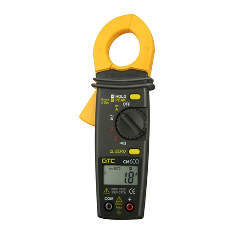
Multimetrix CM 660 User manual

n AC CLAMP-ON METER
CM 660
CM 670
CM 685
ENGLISH User Manual

Table of Contents
1. INTRODUCTION ..............................................................3
Warning.............................................................................................3
1.1 International Electrical Symbols................................................3
1.2 Receiving Your Shipment..........................................................4
1.3 Ordering Information.................................................................4
2. PRODUCT FEATURES .....................................................5
2.1 Control Features .......................................................................5
2.2 Display Features.......................................................................7
2.3 Button Functions.......................................................................8
2.3.1 Auto-off Function...........................................................8
2.3.2 HOLD Button ................................................................8
2.3.3 RANGE Button..............................................................9
2.3.4 MIN/MAX Button ...........................................................9
2.3.5 PEAK Button...............................................................10
3. SPECIFICATIONS ..........................................................11
3.2 Electrical Specications ..........................................................11
AC Volts (TRMS) ....................................................................11
DC Volts .................................................................................11
AC Amperes (TRMS) ..............................................................11
DC Amperes - (CM 685 only)..................................................11
Resistance (Ω) .......................................................................12
Continuity ( ) ........................................................................12
Frequency (Hz) .......................................................................12
Temperature (K type t/c) .........................................................12
3.3 Environmental Specications..................................................13
3.4 Mechanical Specications ......................................................13
3.5 Safety Specications ..............................................................13
4. OPERATION ..................................................................14
4.1 Preparation Before Use ..........................................................14
4.2 AC Current Measurement.......................................................15
4.3 DC Current Measurement - (CM 685 only).............................16

4.4 AC Voltage Measurement.......................................................17
4.5 DC Voltage Measurement.......................................................18
4.6 Frequency Measuring Using Current Input.............................19
4.7 Frequency Measuring Using Voltage Input.............................20
4.8 Resistance Measurement .......................................................21
4.9 Continuity Test ........................................................................22
4.10 Temperature Measurements...................................................23
5. MAINTENANCE .............................................................24
5.1 Warning ..................................................................................24
5.2 Battery Replacement ..............................................................24
5.3 Cleaning..................................................................................24
Repair and Calibration...........................................................................25
Technical and Sales Assistance ............................................................25
Limited Warranty ...................................................................................26
Warranty Repairs...................................................................................26

AC Clamp-on Meter Model CM 660 / CM 670 / CM 685
3
CHAPTER 1
INTRODUCTION
Warning
These safety warnings are provided to ensure the safety of
personnel and proper operation of the instrument.
• Read the instruction manual completely and follow all safety
information before operating this instrument.
• Only use leads that comply with the IEC 61010. Before using
them, always check that they are in perfect working order.
• Never exceed the protection limit values indicated in the
specications for each type of measurement.
• When the multimeter clamp is linked to the measurement
circuits, do not touch any unused terminals.
• Before changing the function, disconnect the measurement
leads from the circuit measured.
• Never measure resistances on a live circuit.
1.1 International Electrical Symbols
This symbol signies that the instrument is protected by double or
reinforced insulation. Use only specied replacement parts when
servicing the instrument.
This symbol on the instrument indicates a WARNING and that
the operator must refer to the user manual for instructions before
operating the instrument. In this manual, the symbol preceding
instructions indicates that if the instructions are not followed, bodily
injury, installation/sample and product damage may result.
Risk of electric shock. The voltage at the parts marked with this
symbol may be dangerous.

4
AC Clamp-on Meter Model CM 660 / CM 670 / CM 685
1.2 Receiving Your Shipment
Upon receiving your shipment, make sure that the contents are consistent
with the packing list. Notify your distributor of any missing items. If the
equipment appears to be damaged, le a claim immediately with the car-
rier and notify your distributor at once, giving a detailed description of any
damage. Save the damaged packing container to substantiate your claim.
Do not use an instrument that appears to be damaged.
1.3 Ordering Information
Model CM 660.............................................................Cat. #MMX-CM660
Includes clamp-on meter CM 660, lead set (red & black lead) with needle
point test probes, carrying case, 2x1.5V AA batteries and a user manual.
Model CM 670.............................................................Cat. #MMX-CM670
Includes clamp-on meter CM 670, lead set (red & black lead) with needle
point test probes, carrying case, 2x1.5V AA batteries and a user manual.
Model CM 685.............................................................Cat. #MMX-CM685
Includes clamp-on meter CM 685, lead set (red & black lead) with needle
point test probes, carrying case, 2x1.5V AA batteries and a user manual.

AC Clamp-on Meter Model CM 660 / CM 670 / CM 685
5
CHAPTER 2
PRODUCT FEATURES
2.1 Control Features

6
AC Clamp-on Meter Model CM 660 / CM 670 / CM 685
1. Jaw assembly
Jaws open to 1.57" (40 mm)
2. Safety guard
Keep hands behind this protective guard
3. Lever / Trigger
Opens or closes jaws
4. Rotary selection switch
OFF Zero voltage
Hz Frequency and AC current (1000A)
Zero (CM 685) DC current (1000A); Reset 40A range
Hz Frequency and AC voltage (600V)
DC voltage (600V)
Resistance (40MΩ) and continuity
TEMP Temperature (CM 660 and CM 670)
°C °F Temperature (CM 685)
5. SELECT button
Selects or displays various ranges
6. RANGE button
Selects Auto Ranging or Manual Ranging measurement ranges
7. Display
Liquid crystal display
8. Positive and Negative terminals
“COM” : black
“+” : red
9. HOLD button
Freezes last measured value on display
10. PEAK button
Displays the peak value when measuring current
11. MIN /MAX button
Displays the minimum and maximum values of a measurement
NOTE: See §2.3 for button functions

AC Clamp-on Meter Model CM 660 / CM 670 / CM 685
7
2.2 Display Features
Data hold
DC mode
AC mode
Negative polarity
Continuity
Auto range
Peak hold
Range hold
Maximum value
Minimum value
Auto-off enabled
Diode Test
Frequency
Selected temperature
Resistance
Current or Voltage
Low battery

8
AC Clamp-on Meter Model CM 660 / CM 670 / CM 685
2.3 Button Functions
2.3.1 Auto-off Function
Except in the HOLD, MIN/MAX or PEAK function, the clamp-on meter
shuts down automatically approximately 10 minutes after the last mea-
surement. The buzzer sounds (7 beeps) one minute before shutdown.
Pressing any button except SELECT starts a new 10-minute period.
To disable the Auto-off function:
• Turn the rotary switch to OFF
• Press and hold down the HOLD button and set the rotary switch
to any position other than OFF
• The icon disappears and the automatic shutdown
is deactivated
To enable the Auto-off function:
• Turn the rotary switch to OFF
• Set the rotary switch to any position other than OFF
• The icon is displayed and the automatic shutdown
is activated
2.3.2 HOLD Button
This function locks the present displayed value.
When in this mode, the Auto-off function is automatically deactivated.
• Press the HOLD button during the measurement
• The icon appears and the measurement is locked
• To deactivate, press the HOLD button again

AC Clamp-on Meter Model CM 660 / CM 670 / CM 685
9
2.3.3 RANGE Button
The default mode is AUTO RANGE mode (automatic).
• Press the RANGE button to select a measurement range
manually.
• The icon appears and the icon disappears.
• Holding the button down for 2 seconds reverts to back to AUTO
RANGE mode. is displayed and the buzzer is activated.
2.3.4 MIN/MAX Button
Set the selector to one of the following positions: , °C°F (CM685) or
TEMP (CM660/670) or (CM685).
When in this mode, the Auto-off function is automatically deactivated.
To record minimum and maximum values, perform the following steps:
1. Take the measurement and press MIN/MAX once
• The and icons appear and recording minimum and
maximum values has now been activated.
2. Press MIN/MAX a second time
• The and icons ash and the recording is now
stopped.
3. Press MIN/MAX a third time
• The icon shows that the value displayed is the maximum
recorded value.
4. Press MIN/MAX a fourth time
• The icon shows that the value displayed is the minimum
recorded value.
5. Press MIN/MAX a fth time
• The cycle reverts to point 2.
To exit the MIN/MAX mode, hold down MIN/MAX for 2 seconds. The
icons will disappear.

10
AC Clamp-on Meter Model CM 660 / CM 670 / CM 685
2.3.5 PEAK Button
This function records the peak value when measuring current.
To record the peak value, perform the following steps:
1. Press the PEAK button during measurement
The highest measurement is stored in memory. The automatic shut-
down function is deactivated.
2. To cancel the PEAK function, press the PEAK button again
NOTES:
For optimum resolution, press RANGE and select the most suitable range
before activating the PEAK function.
When measuring the peak value for an unknown current, press PEAK in
AUTO mode to lock in the maximum range and avoid any overload.
The function is deactivated.

AC Clamp-on Meter Model CM 660 / CM 670 / CM 685
11
CHAPTER 3
SPECIFICATIONS
3.2 Electrical Specications
AC Volts (TRMS)*
Range Resolution Accuracy Input Impedance
4V 1mV
1.0% ± 5cts
11MΩ <50pF
40V 10mV
10MΩ <50pF400V 100mV
600V 1V
*TRMS - Models CM 670 and CM 685 only
DC Volts
Range Resolution Accuracy Impedance
4V 1mV
0.75% ± 2cts
11MΩ
40V 10mV
10MΩ400V 100mV
600V 1V
AC Amperes (TRMS)*
Range Resolution Accuracy
40A 0.01A 1.5% ± 8cts
400A 0.1A 1.0% ± 5cts
1000A 1A
*TRMS - Models CM 670 and CM 685 only
DC Amperes - (CM 685 only)
Range Resolution Accuracy A Max
40A 0.01A 1.5% ± 8cts
1100400A 0.1A 1.0% ± 5cts
1000A 1A

12
AC Clamp-on Meter Model CM 660 / CM 670 / CM 685
Resistance (Ω)
Range Resolution Accuracy
40Ω 0.1Ω
0.9% ± 2cts
400Ω 1Ω
40kΩ 0.01kΩ
400kΩ 0.1kΩ
4MΩ 0.001MΩ 2.0% ± 2cts
40MΩ 0.01MΩ 5.0% ± 2cts
Continuity ( )
Range Buzzer V Max
400Ω <50Ω ± 25Ω 3.4V
Frequency (Hz)
Range Resolution Accuracy
400Hz 0.1Hz 0.5% ± 5cts
4000Hz
Temperature (K type t/c)
Range Resolution Accuracy
-50 to 436°C 0.1°C
1.0% ± 5cts
-50 to 1100°C 1°C
-58 to 818°F 0.2°F
-58 to 2012°F 2°F
*Accuracy @ 23°C ±5°C, 80% RH Max, Conductor Centered in A, 40-400Hz in AC and Hz
Digital display: 4300-count 3 digit LCD
Polarity: When a negative signal is applied, the symbol appears.
Overload: If the range is exceeded, the symbol is displayed.
Low battery Indicator: is displayed when the voltage supplied by
the batteries is lower than the operating voltage.
Power Supply: 2 batteries - 1.5V type AA (LR6) Alkaline
Auto-off: Automatic shut down after approx 10 min of no use
Sampling: Approx 2 measurements/second for the digital display

AC Clamp-on Meter Model CM 660 / CM 670 / CM 685
13
3.3 Environmental Specications
Operating Temperature: 32º to 122ºF (0º to 50ºC)
80% RH max non-condensing
Storage Temperature: 14º to 140ºF (-10º to 60ºC)
70% RH max non-condensing
Altitude: 6000 ft (2000m)
3.4 Mechanical Specications
Maximum jaw opening: Ø 1.57" (40mm)
Dimensions: 9.49 x 3.58 x 1.77" (241 x 91 x 45mm)
Weight: 13.9 oz (390g)
3.5 Safety Specications
IEC/EN 61010-1 and 2-032 - 600V Cat. III
Pollution Degree 2; Class 2

14
AC Clamp-on Meter Model CM 660 / CM 670 / CM 685
CHAPTER 4
OPERATION
4.1 Preparation Before Use
For your own safety and to prevent damage to the instrument, you
must follow the instructions given in this manual.
This instrument can be used for measurements:
• on circuits in installation category II, in an environment with pol-
lution level 2, for voltages no greater than 600V in relation to the
earth.
• or on circuits in installation category III, in an environment with
pollution degree level 2, for voltages no greater than 300V in
relation to the earth.
Denition of the installation categories (see IEC 61010-1 publication):
CAT II: CAT II circuits are household or similar appliance power circuits,
which may carry medium-level transient over-voltage.
Example: household appliance and portable tool power supplies
CAT III: CAT III circuits are high-power appliance power circuits, which
may carry high-level transient over-voltage.
Example: industrial machinery or instrument power supplies
For your own safety, only use leads that comply with the IEC/EN 61010.
Before using them, always check that they are in perfect working order.

AC Clamp-on Meter Model CM 660 / CM 670 / CM 685
15
4.2 AC Current Measurement
Automatic measurement ranges: 40 to 1000AAC (3 ranges)
• Turn the rotary switch to the range
• Remove the test leads before measuring current
• Clamp the jaws around the conductor to be measured
• Take the current reading after it stabilizes
Warning: “-----” indicates that the capacity has been exceeded.
TM
CM 660
CAT III
HOLD
600V
COM
Hz
OFF
SELECTRANGEMIN/MAXPEAK
OFF
TEMP
.
Hz
V
MAX
CORRECT INCORRECT
TM
CM 660
CAT III
HOLD
600V
COM
Hz
OFF
SELECTRANGEMIN/MAXPEAK
OFF
TEMP
.
Hz
V
MAX

16
AC Clamp-on Meter Model CM 660 / CM 670 / CM 685
4.3 DC Current Measurement - (CM 685 only)
Automatic measurement ranges: 40 to 1000ADC (3 ranges)
• Turn the rotary switch to the range
• Press the SELECT button to reset the probe (reset is only avail-
able on the 40A range)
• Remove the test leads before measuring current
• Clamp the jaws around the conductor to be measured
• Take the current reading after it stabilizes
Warning: “-----” indicates that the capacity has been exceeded.
The icon indicates reversal of the contact point’s polarity.

AC Clamp-on Meter Model CM 660 / CM 670 / CM 685
17
4.4 AC Voltage Measurement
Automatic measurement ranges: 4 to 600VAC (4 ranges)
• Turn the rotary switch to the range
• Insert the red lead to the red “+” input jack and the black lead to
the black "COM" input jack
• Bring the test probe tips into contact with the test points.
• Take the voltage reading after it stabilizes
Warning: “-----” indicates that the capacity has been exceeded.
TM
CM 660
CAT III
HOLD
600V
COM
Hz
OFF
SELECT RANGE MIN/MAX PEAK
OFF
TEMP.
Hz
V
MAX

18
AC Clamp-on Meter Model CM 660 / CM 670 / CM 685
4.5 DC Voltage Measurement
Automatic measurement ranges: 4 to 600VDC (4 ranges)
• Turn the rotary switch to the range
• Insert the red lead to the red “+” input jack and the black lead to
the black "COM" input jack
• Take the voltage reading after it stabilizes
Warning: “-----” indicates that the capacity has been exceeded.
The icon indicates reversal of the contact point’s polarity.

AC Clamp-on Meter Model CM 660 / CM 670 / CM 685
19
4.6 Frequency Measuring Using Current Input
20 to 4000Hz (2 ranges)
• Turn the rotary switch to the range
• Press the SELECT button to measure the frequency ( will
appear on the display)
• Clamp the jaws around the conductor to be measured
• Press the SELECT button to display the current
Warning: “-----” indicates that A <2A and F <20Hz
TM
CM 660
CAT III
HOLD
600V
COM
Hz
OFF
SELECT RANGE MIN/MAX PEAK
OFF
TEMP.
Hz
V
MAX
Other manuals for CM 660
1
This manual suits for next models
2
Table of contents
Other Multimetrix Measuring Instrument manuals