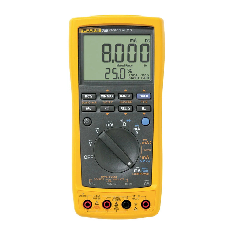
Fluke 93 User manual

FLUKE AND PHILIPS THE GLOBAL ALLIANCE IN TEST &MEASUREMENT
Fluke 93/95/97
Philips PM93/95/97
SCOPEMETER
Service Manual
Ruker 915970
Philipe: 4622 872 05349
920121
Warning: These servicing instructions are for use by qualified personnel oniy. To reduce the risk
of eiecthc shocks do not perform any servicing other than that specified in the operating
instructions uniess you are fully qualified to do so.
FLUKE

IMPORTANT
In correspondence concerning thie instrument please give the model number and serial number as located on
the type number plate on Ihe Instrument
All moditicallons up to production data 21 january 1992 are Incorperated In this manual.
For your reference:
Model number: PMxx Fluke xx
Code number :9444 yyy yyyyy 9444 yyy yyyyy
Serial number: DM nn mmmm DM nn mmmm
Note: The design of this instrument is subject to continuous development and improvement. Consequently,
this instrument may incorporate minor changes In detail from the infom}ation contained in this manual.
©Copyright Philips Export B.V., 1992
All rights reserved. No part of this publication may be reproduced by any means or In any form without written
permission of the copyright owner.
Printed in The r^eiheriande

CONJTENTS
TABLE OF CONTENTS Page
1. SAFETY INSTRUCTIONS 1-1
1.1 INTRODUCTION M
1.2 SAFETY PRECAUTIONS 1-1
1.3 CAUTION AND WARNING STATEMENfTS 1-1
1.4 SYMBOLS 1-1
1.5 IMPAIRED SAFETY M
1.6 GENERAL SAFETY INFORMATION M
2. CHARACTERISTICS 2-1
2.A PERFORMANCE CHARACTERISTICS 2-1
2.B SAFETY CHARACTERISTICS 2-1
2.1 DISPLAY 2-1
2.2 SIGNAL ACQUISITION 2-1
2.3 CHANNELS A&B 2-2
2.4 TIMEBASE 2-4
2.5 TRIGGER 2-5
2.6 SIGNAL MEMORY (MODELS 95 AND 97 ONLY) 2-6
2.7 TRACE DISPLAY 2-6
2-8 SETUP MEMORY (MODEL 95 ONLY) 2-6
2.9 SETUP MEMORY (MODEL 97 ONLY) 2-7
2.10 CALCULATION FACILITIES (MODEL 95 ONLY) 2-8
2.11 CALCULATION FACILITIES (MODEL 97 ONLY) 2-8
2.12 CURSORS (MODELS 95 AND 97 ONLY) 2-9
2.13 MULTIMETER 2-9
2.14 AUTO SETTING 2-14
2.15 GENERATOR (MODEL 93 AND 95) 2-16
2.16 GENERATOR (MODEL 97 ONLY) 2-16

IV CONTENTS
2.17 POWER ADAPTOR BATTERY CHARGER 2-17
2.18 POWER SUPPLY 2-17
2.19 MECHANICAL 2-18
2.20 ENVIRONMENTAL 2-19
2.21 INTERFACE (MODEL 97 ONLY) 2-21
2.22 SAFETY 2-22
2.23 ACCESSORIES 2-23
2.24 SERVICE AND MAINTENANCE 2-23
3. CIRCUIT DISCRIPTIONS 3-1
3-1 INTRODUCTION TO CIRCUIT DiSCRIPTION 3-1
3.1.1 GENERAL 3-1
3.1.2 LOCATION OF ELECTRICAL PARTS 3-1
3.2 FUNCTIONAL BLOCK DISCRIPTION 3-2
3.2.1 INTRODUCTION 3-2
3.2.2 DATA ACQUISITION 3-4
3.3.3 MICROPROCESSOR 3-7
3.3.4 DIGITAL ASIC (D-ASIC) CIRCUITRY 3-9
3.3.5 LCD CIRCUl'mY 3-12
3.4 ANALOG CIRCUITS (A2) 3-14
3.4.1 INTRODUCTION 3-14
3.4.2 OVERVIEW ANALOG CIRCUITS 3-14
3.4.3 ATTENUATOR SECTIONS, CHANNEL A AND B3-14
3.4.4 EXTERNAL (BANANA) INPUT/OUTPOT CIRCUITRY 3-18
3.4.5 ANALOG ASIC (A-ASIC) AND ADC CIRCUITRY 3-20
3.4.6 ANALOG CONTROL CIRCUIT 3-24
3.4.7 GENERATOR CIRCUIT 3-30
3.4.8 BATTERY CHARGER 3-32
3.4.9 POWER SUPPLY 3-34
4. PERFORMANCE VERFICATION PROCEDURE 4-1
4.1 GENERAL INFORMATION 4-1
4.2 STANDARD PERFORMANCE VERFICATION PROCEDURE 4-2
4.3 STANDARD PERFORMANCE VERFICATION PROCEDURE SUMMARY 4-16
4.4 AODmONAL PERFORMANCE VERFICATION PROCEDURE 4-17

CONTENTS V
5.
CALIBRATION ADJUSTMENT PROCEDURE 5-1
5.1 GENERAL INFORMATION 5-1
5.2 RECOMMENDED CALIBRATION ADJUSTMENT EQUIPMENT 5-1
5.3 ENTERING THE CALIBRATION PROCEDURE 5-2
5.4 OPERATING THE CAUBRATION PROCEDURE 5-3
5.5 CONTRAST CALIBRATION ADJUSTMENT PROCEDURE 5-4
5.6 SCOPE CALIBRATION ADJUSTMENT PROCEDURE 5-4
5.6.1 HARDWARE SCOPE CAUBRATION ADJUSTMENTS 5-4
5.6.2 CLOSED CASE SCOPE CALIBRATION ADJUSTMENTS 5-8
5.7 METER CAUBRATION ADJUSTMENT PROCEDURE 5-15
5.8 CALIBRATION ADJUSTMENT PROCEDURE SUMMARY 5-24
6. DISASSEMBLING THE SCOPEMETER 6-1
6.1
GENERAL INFORMATION 6-1
6.2. DISASSEMBLY PROCEDURE 6-1
6.2.1 REMOVING THE BATTERY PACK 6-2
6.2.2 OPENING THE SCOPEMETER 6-2
6.2.3 REMOVING THE ANALOG A2 PCB. TO ENABLE HARDWARE
SCOPE CAUBRATION ADJUSTMENTS 6-4
6.2.4 REMOVING THE DIGITAL A1 PCB 6-4
7.
CORRECTIVE MAINTENANCE 7-1
7,1 DIAGNOSTIC TESTING AND TROUBLESHOOTING 7-1
7.1.1 INTRODUCTION 7-1
7.1.2 TROUBLESHOOTING TECHNIQUES 7-1
7.1.3 DISPLAY AND ERROR MESSAGES 7-2
7.1.4 MAIN TESTS 7-5
7.1.5 TROUBLESHOOTING 7-7
7.1.6 DIGITAL At PCB TROUBLESHOOTING 7-7
7.1.7 ANALOG A2 PCB TROUBLESHOOTING 7-28
72 REPLACEMB^TS 7-40
7.2.1 STANDARD PARTS 7-40
7.2.2 SPECIAL PARTS 7-40
7.2.3 TRANSISTORS AND INTEGRATED CIRCUITS 7-40
7.2.4 STATIC-SENSITIVE COMPONENTS 7-40
7.2.5 REPLACEMENT OF PARTS 7-42
7.3 SOLDERING TECHNIQUES 7.5I
7-3-1 GENERAL SOLDERING TECHNIQUES 7-51
7.3.2 SOLDERING MICRO-MINIATURE SEMICONDUCTORS 7-51

VI CONTENTS
7
A
SPECIAL TOOLS 7-52
7.4.1
EXTENDER FLAT CABLE 7-52
7.5 RECALIBRATION AFTER REPAIR 7-52
7.6 INSTRUMENT REPACKING 7-52
8. MAINTENANCE OF THE PRIMARY CIRCUIT (PM8907/...) 8-1
9. REPLACEABLE PARTS LIST 9-1
9.1 INTRODUCTION 9-1
9.2 HOW TO OBTAIN PARTS 9-2
10. CIRCUIT DIAGRAMS 10-1

1-2 SAFETY INSTRUCTIONS
1.5 IMPAIRED SAFETY
Whenever HIs likely that safety has been Impaired, the Instrument must be turned off and
disconnected from all external voltage sources, and the batteries must be removed. The matter
should then be referred to qualified technicians. Safety Is likely to be impaired if, for example, the
instrument fails to perform the intended measurements or shows visible damage.
1.6 GENERAL SAFETY INFORMATION
WARNING: Removing the instrument covers or removing parts, except those to which
access can be gained by hand, is likely to expose live parts and accessible
terminals which can be dang^ous to life.
The instrument must be disconnected frorr> all voltage sources and batteries must be removed before
rt is opened.
Capacitors inside the instrument can hold their charge even if the instrument has been separated
from all voltage sources and batteries are removed. Components which are important for the safety
of the Instrument may only be replaced by components obtained through your local FLUKE/PH ILI PS
organization. These components are Indcated by an asterisk (*) In the parts list sechon (chapters).

CHARACTERISTICS 2-1
2CHARACTERISTICS
A. Performance Characteristics
PHILIPS and FLUKE guarantee the properties expressed in numerical values with stated
tolerance. Specified non-tolerance numerical values indicate those that coutd be nomir^lly
expected from the mean of arange of identical instruments.
•For definitions of terms, reference is made to lEC Publicatjon 351-1
.
•The accuracy of all measurements Is within i: {(Si of reading) ±(one least-significant digit)}
from 18C to 28C.
Add 0.1 X(specified accuracy)/C for <16C or >28C ambient.
B. Safety Characteristics
The Instrument has been designed and tested in accordance with IEC Publication 348, Safety
Requirements for Electronic Measuring Apparatus, and has been supplied in asafe condition. This
manual contains Information and warnings that must be followed by the user to ensure safe operation
and to keep the instrument in asafe condition.
2.1 DISPLAY
CHARACTERISTICS SPECIRCATtONS ADDITIONAL INFORMATION
Type LCD
>Useful Screen Area 64 mm x64 mm 1div equals 25 pixels.
1div equals 8.75 mm.
Resolution 240 x240 pixels
•Contrast Ratio Adjustable via LCD Menu.
•Backlight (Model 97 only) Electro Luminescence
2.2 SIGNAL ACQUISITION
•Sampling Type
@1ps/div...60s/dlv
@10 ns/div...500 ns/di
V
Real Time
Quasi Random
•Maximum Sample Rate 25 MS/s Sampling Rate depends on tims/div
setting.
-Maximum Vertical
(voltage) Resolution 6bits Over 10 divisions.
*Maximum Horizontal
(time) Resolution
25 Samples/div Per Channel-
-Record Length
With capture 20 div 512 Samples Per Channel.
With capture 10div 256 Samples Per Channel.

2-2 CHARACTERiSTiCS
CHARACTERISTICS SPECIFICATIONS
-Acquisition Time
(for 20.4 dlv)
60s/dlv...1 ys/Olv
500 ns/div...10 ns/div
«Sources
•Acquisition Modes
20-5 X tlme/div -i- 140 ms
20.5 Xtime/div +120 ms
Channel A
Channel ±B
mV Input
1Channel Only
2Channels
ADDITIONAL INFORMATION
Excluding delay time.
Delay time Is the selected trigger
delay.
Excluding delay time.
In Quasi-Random Mode, the
acquisition time depends on
triggers.
CHAN A, CHAN B
Chopped Mods from
60sydiv...50 ps/div.
Alternating Mode from
20 ps/drv...10 ns/div.
2.3 CHANNELS A&B
*Signal Inputs Isolated BNC Signal Input BNC commons are
connected together.
Common Input
•Input Impedance
Rparallel
Black Safety Banana Jack
1MO± 1%
Part of External Trigger Input.
Frequency dependent, see
Figure 2.1.
For DC coupled input. For AC
coupled input or GND, add 22 nF in
series with Rand Cparallel.
Cparallel 25 pF
MAX. INPUT
IMPEDANCE
Figure 2. 1Max. Iriput Impedance Versus Frequency
rvn

CHARACTERISTICS 2•3
CHARACTERISTICS SPECIFICATIONS ADDITIONAL INFORMATION
•Input Coupling AC DC GND Sequence: ac-doGND (pre-charge
ac), and back to ac.
•Maximum Input Voltage 300 V
(rms)
MAX. PEAK
VOLTAGE
Figure 2.2 Max Input Voltage Versus Frequency
•Defiection Coefftelent
Frequency dependent see fig. 2.2
Between BNC inner and outer
contact. Outer BNC contacts and
Ground (Black) Banana Jack are
internally connected together.
Steps 1mV/dlv...2 mV/div
(Models 95 and 97 only)
Steps 5mV/d(V...100V/div
Error Limit
Overall
Nonlinearity ±(2%±1digit)
±(2% 11cfgit)
Dynamic Range 9.5 div
4div
Position Range
(move control)
-4dlv...+ 4div
Frequency Response
Lower Transition Point
of Bandwidth
Only (or repetitive signals and
llmebase 60s...1mS- if one of the
channels is in this sensitivity, both
channels will be switched to
Average =4.
In a1-2-5 sequence ot 14 positions.
Add 3% tor 1mV and 2mV
per (EC 351 for frequencies
<1MHz.
for frequencies <10 MHz.
for frequencies up to 50 MHz.
Zsource =500.
DC Input Coupling DC
AC Input Coupling -3dB <10Hz < 1Hz including 10 MO probe.
Upper Transition Point >50 MHz (-3 dB)
of Bandwidth Subtract 5MHz for <18 ®C
and >28 Ambient.
Rise time 7ns.

2-4 CHARACTERISTICS
CHARACTERISTICS SPECIFICATIONS ADDtTtONAL INFORMATION
•Max. Baseline Inetabllity
Jump 0.1 dlvor 1mV The baseline is automaticalfy
reac|usted after switching the
attenuator or AC/DC/GND.
•Average
(Models 95 and 97 only)
Running Average.
Maximum Constant 256x
Constant in Roll lOX
•MIN MAX
(Models 95 and 97 only)
Channel Aonly.
Tlmebase setting
Pulse-wkJlh for 1X%
Probability
Pulse-wWtti for 25%
Probability
S1^s/dlv
40 ns
10 ns
*ZOOM
(Models 95 and 97 only)
Expansion or compression in 1,2,5
sequence around the 4th division.
Range for Delay <640div
TIMEBASE
•Modes Recurrent
Single Shot
Roll Automatic selected.
«Ranges
Recurrent 5s/dlv...10 ns/div
Dual Channel Chopped 5a/div...50 pa/di
v
Dual Channel Alternate 20 pa/div... 10 ns/div
Single Shot 5s/dlv...10 ns/dlv Every sweep needs atrigger.
Asweep first; Bsweep arms
automatically.
For 500 ns, 200 ns, and 100 ns; an
automatic Interpolation lakes place.
Chopped.
Roll Mode 60s/div...10s/dlv
Maximum Timabase Error ±0.1 %±1LSB

CHARACTERISTICS 2-5
CHARACTERISTICS SPECIFICATIONS ADDITIONAL INFORMATION
2.5 TRIGGER
•Sources Sheeted Independently.
Channel ASignal
Channel BSignal
External Trigger Input
GHANA
CHAN B
EXT
*External Trigger Input
Connector Dual Salety Banana Jack External Trigger Input common
(low) jack is electrically
connected to the Channel Aand
Channel Bcommons (outer
contact of BNC's).
'External Tiigger Input
Impedance
Rparallel 1MJ^±1% If used for mV DC >1MQ.
Cparallel 25 pF Including Banana to BNC adapter.
•Trigger Error For frequencies <1MHz.
Voltage Level ±1 LSB
±0.5 div
5s;dlv...50MS/dlv.
20 |i8/div...10 ns/div.
Time Delay ±1 LSB ±5 ns
•Maximum External Trigger
Input (rms)
300 VFrequency dependent, see fig. 2.2.
•Trigger Sensitivity For Models 95 and 97, values must
be multiplied by 5In 2mV/dIv. and
1mn/dfv.
Charrnel Aor B
a100 MHz
^60 MHz
@10 MHz
54 div
51.5 div
50.5 div
External Trigger input TTL logic compatible using 10;1
attenuation Probe.
•Trigger Slope Selection positive going
negative going
•Trigger Level Control
Range
Channel Aor B
Trigger at 50%
External Trigger Input
±4 div
0.5 X peak/t^ak value
Fixed @TTL:10 Measured during 20 ms.
Switchable lo TTL via set-up menu.

2-6 CHARACTERISTICS
CHARACTERISTICS SPECIFICATIONS ADDITIONAL INFORMATION
N-cycle mode
(Models 95 and 97 only)
5s/fliv...1 ^s/dJV, N= 2...255 For tlmebase settings from
20^s/dfv...1 ps/div acquisition and
trigger on Channel Aonly.
Events (5s/div...1 ys/div) 1...1023 Start via Ext; count with channel A,
•Trigger Delay
Range •20... 640 div
2.6 SIGNAL MEMORY (MODELS 95 AND 97 ONLY)
•Signal Memory Size
Memoiies 8Memory *1 up to #8.
Memory Depth 512 words
Wordlength 6Bit
Functions Store Storage of signals.
Save Contents of Channel Aand
Channel Bare saved in temp
memory #1 and #2, and (A ±B) in
temp memory #3,
2.7 TRACE DISPLAY
•Sources Channel AAMaximum of 4traces plus Avs B
Channel B
A±B
Avs B
can be selected.
Memory #1 up to #8 (Models 95 and 97 only).
*Position range
Horizontal +4dfv...- 16.5 div
Vertical •4(jlv...+ 4div From screen center, select per
trace.
2.8 SETUP MEMORY (MODEL 95 ONLY)
•Memory Size 8maximum Combined with waveform.

CHARACTERfSTICS 2-7
CHARACTERISTICS SPECIFICATIONS
2.9 SETUP MEMORY (MODEL 97 ONLY)
•Memory Sl2e 10 maximum
•Functions Save
Delete
Recall
With soft up/down keys Next
Previous
*Initial setup
selection of AUTO SET only Amplitude
or>ly Time
Time and Amplitude
trace identification on/off
trigger identification on/off
trigger sensitivity external 0.2V/2V
Clear after Hold^un on/off
refresh time %RECORD
in scope mode infinite
2seconds
5seconds
10seconds
60 seconds
ADDITIONAL INFORMATION
Front Panel setups.
Actual front panel settings are
stored In memory* replacing
contents of memory location
Indicated on LCD.
Contenis of memory tocation
indicated on LCD are deleted.
Actual front panel settings are
replaced by contents of memory
location indicated on LCD.
Actual settings are replaced by
contents of the next (+1 )memory
location Indicated on LCD.
Actual settings are replaced by
contents of the previous (-1)
memory location indicated on LCD.

2-S CHARACTERISTICS
CHARACTERISTICS SPECIFICATIONS ADDITIONAL INFORMATION
2.1 0CALCULATION FACILITIES (MODEL 95 ONLY)
•Measurement Functions
della V
della 1
RMS value
Mean (Average) value
Peak to Peak value
Rise or Fall lime
Frequency
1delta t
Maximum value
Minimum value
Phase
Trigger time to cursor
Ratio
Maximum of 56imultar>90us
measurement functions.
Vof portion between portion.
£xpresslor> of value in %or
absolute on any one of the above
values.
2.11 CALCULATION FACILITIES (MODEL 97 ONLY]
*Measurement Functions Maxmum of 5 simultaneous
measurement functions.
delta V
delta t
RMS value
Mean (Average) value
Peak to Peak value
Rise or Fall time
Frequency
1delta t
Maximum value
Minimum value
Phase
Trigger time to cursor
Ratio
\
>of portion between portion.
Expression of value In %or
absolute on any one of the above
values.
•Mathematics Multiplication
Add
Subtract
Fitter
Invert
Integrate
of whole memory or Channel.
For timebase settings
20 PS...10 ns, only displayed
Channels can be used.

CHARACTERISTICS 2-g
CHARACTERISTICS SPECIFICATIONS
2.12 CURSORS (MODELS 95 AND 97 ONLY)
Horizontal
Display Resolution
Digital Readout Resolution
Error Limit
Cursor Range
Vertical
Display Resolution
Digital Readout Resolution
Error Limit
25 parts per div
3digits
±0.1%±1 LSB
Visible part of signal
25 parts per dIv
3digits
±2%
ADDITIONAL INFORMATION
Cursors cannot pass each other.
Referred to Input at BNC or Probe
tip, after Probe recalibration.
2.13 MULTIMETER
The Multimeter uses the Channel Ainput for VDC &VAC measuremenlsand the Safety Banana Jack
Inputs for Resistance, Diode Test, Continuity, and DC mV measurements. An Internal reference is
used to optimize the accuracy of the Channel AInput and any probes used. The accuracy of all
Multimeter measurements Is within ±{(% of reading) +(number of least-significant digits)) from 18 *C
to 28 ®C with relative humidity up to 20% fora period of one year after calibration. Add 0.1 x{specified
accuracy)/C for 18 or 28 ”C Ambient.
•Displayed range include used probe, if calibrated.
•Values listed are without attenuating probe.
•AVrms AC and VDC dual display mode Is optimized for power line (mains) related
measurements.
•DC Voltage
Ranges 300 mV. 3V. 30V &300V Manual or automatic ranging on
peak voltage. High Voltage x10
Probe extends measurement to
600V. Peak voltage is 2.5x range,
except 375V In 300V range.
Resolution 0.1 mV, 1mV, 0.01V,
&0.1V Multiply x10 with High Voltage
Probe-
Accuracy ±(0.5% +5)
Digital Display 3000 counts Up to 4500 counts, 3500 counts in
300V range.
Display update
Response Time <300 ms
<3.5s
Zeroing automatic
Series Mode Rejection
Ratio
>50 dB @50 Kz
or 60 Hz

2-10 CHARACTERISTICS
CHARACTERISTICS SPECIFICATIONS ADDITIONAL INFORMATION
•AC Voltage
Ranges 300 mV. 3V, 30V, 250V Manual or automatic ranging on
peak voltage.
High Voltage xIO Probe extends
measurement to 600V. Peak
voltage is 2.5x range and 375V in
250V range.
Resolution 0.1 mV, 1mV, 0.01 V. 0.1V Multiply X10 with High Voltage
Probe.
Accuracy (AC Coupled)
Using High Voltage 10:1
Probe
Valid from 5%.. 100% of range.
50 Hz...60 Hz ±(1%+ 10)
20 Hz...20 kHz ±(2%+ 15)
5HZ...1 MHz
Accuracy (DC Coupled)
Using High Voltage 10:1
Probe
±(3% + 20)
50 Hz... 60 Hz ±(1% +10)
1Hz.. .20 kHz ±(2% + 15)
Crest Factor Meter prevents crest factor errors
by autoranging on Input waveform
peaks.
Digital Display 3000 counts Up to 4500 counts,
at 260V range: 2500.
Display Update c300 ms
Response Time
@Input freq >50 Hz <3.5s
SMOOTH < 10s
FAST <Is
DC Common Mods
Rejection Ratio
> 100 dB @dc
>100 dB @50, 60. or 400 Hz
AC Common Mode
Rejection Ratio >60d6 @dc..60Hz

CHARACTERISTICS 2-11
CHARACTERISTICS SPECIFICATIONS ADDHIONAL INFORMATION
«Resistance
Open Circuit Voltage <4V
Full Scale Voltage
300n...3 Mfi < 250 mV
30 mi <2V
Ranges 300Q, 3kii, 30 kil
300 kD. 3Ma 30 MLl Manual or automatic ranging.
Resolution 0.10.0.001 kil 0.01 kO.
0.1 kO, 0.001 Mn, 0.01 MO
Accuracy ±(0.5% +5)
Digital Display 3000 counts Up to 4500 counts, at 30 MO 3000
Measurement Current 0.5 mA...70 nA Decreases as range increases.
Display Update <300 ms
Response Time <3.5$
SMOOTH <10s
FAST <Is
Protection 600V RMS
Continuity
Beeps if resistance is <:
•Diode Test
Maximum Voltage
Range
Resolution
Accuracy
Digital DiS(^ay
Measurement Current
Display update
Response Time
SMOOTH
FAST
Protection
Polarity
Continuity (Alert)
5% of selected
OL Is indicated if measured voltage
IS >2.8V.
4V
2.800V
0.001V
±{2% +5)
3000 counts If value >2800 readout gives OL.
0.5 mA
<300 ms
<3.5s
<10s
<1s
600 VRMS
on RED Banana Jack
-on BLACK Banana Jack
Beeps if reading is below 1
V

2•12 CHARACTERISTICS
CHARACTERISTICS SPECIFICATIONS ADDITIONAL INFORMATION
•DC mV Banana Jack Inputs Used for Accessory (lr>cludlng
Temperature) input.
Ranges 300 mV &3V Manual or Automatic ranging.
Resolution 0.1 mV &1mV
Accuracy ±(0.5% 4- 5)
Digital Display 3000 Counts Up to 3500 Counts.
Display update <300 ms
Response Time
SMOOTH
FAST
<3.5s
<10s
<Is
Input •K on RED Banana Jack
on BLACK Banana Jack
•Multimeter Math (Display)
Functions (Models 95 and
97 only)
Relative ZERO delta Displayed Value =Reading
Reference Reading.
%Change {% Relative) ZERO %delta Displayed Value «{(Reading/Refe
rence Reading) -1} x100.
%Scale Displayed Value b{(Reading-Set
0% Reading)/{Set 1(X)% Reading-
Set 0% Reading)} x100%.
SetO^ Reference SetO% Present, Maximum. Minimum,
Average.
Set 100% Reference Set 100% Present. Maximum, Minimum,
Average.
Power with respect to
1mW in selected load
resistance
dBm
Select load resistance 1200, 1000, 900, 800, 600,
500, 300, 250, 150, 135,
125, 110, 93,75, 60&50
Voltage Ratio in dS with
respect to tV dBV
Audio power WATTS or dBW
Select load resistance 50,16, 8, 4. 2&in

CHARACTERISTICS 2-13
CHARACTERISTICS SPECIFICATIONS ADDITIONAL INFORMATION
•Other Multimeter Operating Modes
Touch Hold HOLD Causes the meter to capture the
ne)(t measured reading (and beep)
when anew stable measurement
has been detected. When first
enabled, the numeric display is
frozen (held) until astable
measurement is detected. Stable
measurements are defined as
within ±100 display counts for 4
measurements ("Is.); and above a
floor of 200 display counts mvolts
(300 counts in ac, below 4000
counts in Oar>d below 2800 counts
in diode). Overload Is avalid stable
condition except In £2 and diode
test.
MIN MAX recording
(Models 95 and 97 only) RECORD Simultaneous displays o1
Maximum. Minimum. Peakto Peak.
Average* arvJ Present reading.
•Frequency
Range 1H2...5 MHz Manual for frequencies < 20 Hz.
Accuracy +/- (0.5% + 2 counts)
Tlmebd&e Accuracy +/-0.01%
Resolution 4digits
Measuring Time 3.5s gradually degradation from 100 Hz
SMOOTH <10s and down.
FAST <1sRunning average over 32
measurements.
Ranging Automatic
•AUTO RANGE Vdtage and Time are coupled.
Voltage Range_Up 3500 Maximum reading in manual range
@300 mV, 3V> 30V :4500.
Voltage Range.Down 0300 @external Input: 3500.
Time Range_Up
5ms. ..50 us >6periods fn display TIME switch selects manual
timebase.
20 US...1 us >4periods in display AUTOSET starts timebase ranging.
Ttme Range.Down
5ms...50 )is <1.5 periods in display
20 US...1 us <0.75 periods in display
This manual suits for next models
2
Table of contents
Other Fluke Measuring Instrument manuals

Fluke
Fluke 435-II Instruction manual

Fluke
Fluke 43B User manual

Fluke
Fluke VIBGUARD IIoT User manual

Fluke
Fluke OptiView User manual

Fluke
Fluke CO-220 User manual

Fluke
Fluke MultiFiber Pro User manual
Fluke
Fluke a3001 FC User manual

Fluke
Fluke FiberInspector Pro OFTM-5352 User manual

Fluke
Fluke PQ Window User manual

Fluke
Fluke 700G01 User manual
Popular Measuring Instrument manuals by other brands

edc
edc SM-7204 user guide

PCB Piezotronics
PCB Piezotronics IMI SENSORS 625B10 Installation and operating manual

Endress+Hauser
Endress+Hauser PROFIBUS PA Levelflex FMP56 operating instructions

LSI LASTEM
LSI LASTEM Heat Shield Quick user guide

Clarke
Clarke CM145 User instructions

SICK
SICK NAV200 operating instructions