Fluke FIBER QUICKMAP User manual

January 2011, Rev. 34/2016
©2011, 2013, 2015, 2016 Fluke Corporation
All product names are trademarks of their respective companies.
FIBER QUICKMAP™
Multimode Troubleshooter
Users Manual

LIMITED WARRANTY AND LIMITATION OF LIABILITY
Fluke Networks mainframe products will be free from
defects in material and workmanship for one year from the
date of purchase, unless stated otherwise herein. Parts,
accessories, product repairs and services are warranted for
90 days, unless otherwise stated. Ni-Cad, Ni-MH and Li-Ion
batteries, cables or other peripherals are all considered parts
or accessories. This warranty does not cover damage from
accident, neglect, misuse, alteration, contamination, or
abnormal conditions of operation or handling. Resellers are
not authorized to extend any other warranty on Fluke
Networks’ behalf.
To obtain service during the warranty period, contact your
nearest Fluke Networks authorized service center to obtain
return authorization information, then send your defective
product to that Service Center with a description of the
problem.
For a list of authorized resellers, visit
www.flukenetworks.com/wheretobuy.
THIS WARRANTY IS YOUR ONLY REMEDY. NO OTHER
WARRANTIES, SUCH AS FITNESS FOR A PARTICULAR
PURPOSE, ARE EXPRESSED OR IMPLIED. FLUKE NETWORKS IS
NOT LIABLE FOR ANY SPECIAL, INDIRECT, INCIDENTAL OR
CONSEQUENTIAL DAMAGES OR LOSSES, ARISING FROM
ANY CAUSE OR THEORY.
Since some states or countries do not allow the exclusion or
limitation of an implied warranty or of incidental or
consequential damages, this limitation of liability may not
apply to you.
4/15
Fluke Networks
PO Box 777
Everett, WA 98206-0777
USA

i
Contents
Introduction .................................................................................... 1
Registering Your Product .............................................................. 1
The Fluke Networks Knowledge Base......................................... 1
Symbols ............................................................................................ 2
Safety Information.................................................................... 2
Battery Installation and Life.......................................................... 4
Physical Features............................................................................. 4
Display Features.............................................................................. 6
Settings ............................................................................................ 8
The Connector Adapter................................................................. 9
How to Clean Connectors.............................................................. 10
How to Use a Mechanical Device ............................................ 10
How to Use Swabs, Wipers, and Solvent................................ 11
Protect Connectors .................................................................... 12
About Launch and Receive Fibers ................................................ 13
How to Use the Troubleshooter................................................... 14
Measurement Results..................................................................... 16
Maintenance ................................................................................... 20
Contacting Fluke Networks........................................................... 21
Options and Accessories ................................................................ 22
Specifications................................................................................... 22

ii
FIBER QUICKMAP Users Manual

1
Introduction
The FIBER QUICKMAP™Multimode Troubleshooter does these
tests to help you find incidents on multimode fiber optic cables:
Maps the connections in multimode fiber plants by
showing the number of incidents on the fiber and the
distance to each incident.
Measures the length of multimode fiber optic cables
Measures the distance to reflective and loss incidents
Measures the reflectance of connectors
Registering Your Product
When you register your product with Fluke Networks you get
access to valuable information on updates, troubleshooting
procedures, and other support services.
To register online, go to www.flukenetworks.com/registration.
The Fluke Networks Knowledge Base
The Fluke Networks Knowledge Base gives answers to typical
questions about Fluke Networks products and includes
information on technology and procedures for network and
cable tests. To see the Knowledge Base, go to
www.flukenetworks.com, then click SUPPORT > Knowledge
Base.

2
FIBER QUICKMAP Users Manual
Symbols
Safety Information
Warning: Class 1 Laser
To prevent possible damage to your eyes caused by
hazardous radiation:
Do not look directly into optical connectors. Some
optical equipment emits invisible radiation that can
cause permanent damage to your eyes.
Do not turn on the troubleshooter unless a fiber is
attached to the port.
Warning or Caution: Risk of damage to or destruction of
equipment or software. See explanations in the manual.
Warning: Risk of electrical shock.
Warning: Class 1 laser. Risk of damage to your eyes caused
by hazardous radiation.
Conforms to relevant European Union directives
Conforms to relevant Australian standards
Listed by the Canadian Standards Association
CSA C22.2 No. 61010.1.04
Conforms to FCC Rules, Part A, Class A
Do not put products that contain circuit boards into waste
containers. Refer to local regulations for disposal
procedures.
This key turns the Product on and off.

3
Safety Information
Do not use a magnifying device to look at the optical
outputs without the correct filter.
Use of controls, adjustments, or procedures that are
not in this manual can cause exposure to hazardous
radiation.
Caution
To prevent damage to fiber connectors, to prevent
data loss, and to make sure that your test results are
as accurate as possible:
Do not connect APC connectors to the troubleshooter.
An APC connector will cause damage to the fiber
endface in the connector on the troubleshooter.
Use only test cords that comply with GR-326-CORE
specifications and have UPC connectors. Other test
cords can cause unreliable measurements.
Use the correct procedures to clean all fiber connectors
before each test. If you do not do this or if you use
incorrect procedures, you can get unreliable test
results and can cause permanent damage to the
connectors.
Put protective caps on all connectors when you do not
use them.
Do not connect the troubleshooter to a network that
is on. If you do, the troubleshooter can cause problems
in the network.
If ACTIVE LINE blinks, immediately disconnect the
troubleshooter from the fiber. Optical power levels
more than +7 dBm can cause damage to the detector
in the troubleshooter.

4
FIBER QUICKMAP Users Manual
The troubleshooter senses optical signals only at
850 nm. If there might be signals at other wavelengths
on a fiber, use a different instrument to make sure that
the fiber is not active before you connect the
troubleshooter to the fiber.
Battery Installation and Life
fjy03.eps
Figure 1. How to Install the Batteries
The troubleshooter can do approximately 1500 tests before you
must replace the batteries.
Physical Features
See Figure 2.
Output port with SC adapter and UPC endface
Starts a test
On/off key
Navigation keys
AA
IEC LR6
NEDA 15A
Note: Fluke Networks recommends alkaline batteries.

5
Physical Features
Press to see the setup menu, to select an item, and to save
a setting
LCD display
gbw04.eps
Figure 2. Physical Features
6
FIBER QUICKMAP Users Manual
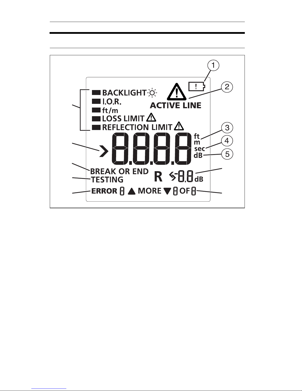
Display Features
gbw01.eps
Figure 3. Display Features
When the low battery symbol shows, replace the batteries
soon. See page 4.
When you press , the troubleshooter looks for an
850 nm optical signal on the fiber. If there is an 850 nm
signal stronger than -15 dBm on the fiber, ACTIVE LINE
blinks and the troubleshooter will not do a test.
Caution
If ACTIVE LINE blinks, immediately disconnect the
troubleshooter from the fiber. Optical power levels
more than +7 dBm can cause damage to the detector
in the troubleshooter.
F
G
H
I
J
K
L
Other manuals for FIBER QUICKMAP
2
Table of contents
Other Fluke Measuring Instrument manuals

Fluke
Fluke 700G Series Configuration guide

Fluke
Fluke 771 User manual

Fluke
Fluke 985 User manual

Fluke
Fluke CO-220 User manual

Fluke
Fluke DTX-CLT CertiFiber User manual

Fluke
Fluke 80i-110s User manual

Fluke
Fluke 732a User manual

Fluke
Fluke i100 User manual

Fluke
Fluke MicroMapper User manual

Fluke
Fluke 80PK-1 User manual

Fluke
Fluke 773-II User manual

Fluke
Fluke DSX-600 CableAnalyzer User manual

Fluke
Fluke 345 Use and care manual

Fluke
Fluke 1623-2 User manual

Fluke
Fluke i430-Flexi-TF User manual

Fluke
Fluke ProcessMeter 787 User manual

Fluke
Fluke 902 FC User manual

Fluke
Fluke 189 User manual

Fluke
Fluke 789 User manual

Fluke
Fluke 1623-2 User manual


