Fluke Nuclear Associates 07-453 User manual

i
MODEL 07-453
X-RAY PULSE
COUNTER/EXPOSURE
TIME METER
Instruction Manual
May 2006
Manual No. 07-453-1 Rev. 3
2006 Fluke Corporation, All rights reserved. Printed in U.S.A.
All product names are trademarks of their respective companies

ii
Fluke Biomedical
Radiation Management Services
6045 Cochran Road
Cleveland, Ohio 44139
440.498.2564
www.flukebiomedical.com/rms

iii
Contents
Section 1: Description ...................................................................................................................... 1-1
Section 2: General Instructions ...................................................................................................... 2-1
Section 3: Battery Replacement..................................................................................................... 3-1
Section 3: Oscilloscope Output ...................................................................................................... 3-1
Section 4: Calibration ...................................................................................................................... 4-1
Section 4: Exposure Time Conversion Chart................................................................................ 4-1
Section 5: Warranty .......................................................................................................................... 5-1
Section 6: Service Information ....................................................................................................... 6-1
Section 7: Specifications.................................................................................................................. 7-1
Section 8: Appendix ......................................................................................................................... 8-1

(Blank page)

Section 1
Description
1.1 Product Description
The Fluke Biomedical Model 07-453 X-ray Timer/Counter is used to measure the duration of radiation
output produced by X-ray generators. The Model 07-453 is a solid-state, digital instrument designed
specifically for service personnel in assessing the performance of radiation generator timing controls.
The instrument is a noninvasive instrument, which samples the radiation beam of x-rays.
The Model 07-453 can be used as follows:
1) To count the number of x-ray pulses produced by half-wave and full-wave rectified machines. It
will count the output pulses typically 60 pulses per second for half-wave rectified machines or 120
pulses per second for full-wave. Dental x-ray machines are usually half-wave rectified.
2) To measure the length of radiation output when the x-ray output is steady state such that "pulsing"
does not exist. X-rays that generate steady outputs include 3-phase AC medical x-ray machines;
capacitor discharge x-ray machines and DC operated x-rays.
3) To measure the "on time" or relay contact closure time by counting the number of pulses of AC
line voltage (90 to 130 VAC) via the front panel input jacks and test leads.
The Model 07-453 replaces not only mechanical impulse counters, but also other electronic counters.
The small hand held size conveniently fits in a small toolbox, jacket pocket or handbag.
There is no "Reset" button. The Model 07-453 automatically resets at the beginning of each exposure,
holding the reading until the next exposure.
The most convenient way of using the 07-453 is to place it directly under the x-ray head. Step back, take
the exposure and then read the exposure time in pulses or milliseconds. An optional remote sensor is
also available to allow use of the 07-453 at distances of up to 10 feet away from the x-ray.
It is important that the user be thoroughly familiar with the contents of this manual before performing any
tests on radiation generating equipment. It is also imperative that the user be thoroughly qualified, and
familiar with safety precautions and other practices relating to radiation generators.

(Blank page)

Section 2
General Instructions
2.1 General Instructions
Switch Settings
The front panel selector toggle switch on the Model 07-453 has 3 positions, 'OFF', 'PULSES", and
"MILLISECONDS'. The switch is OFF in the center position.
PULSES
When the switch is moved to the 'PULSES' position, the instrument will be used for measuring output
pulses from half-wave or full-wave rectified machines as well as AC line voltage pulses. Normally, each
full second of exposure will produce 60 pulses. An exposure of 2/10 second will read 12 for example.
Refer to the chart on page 5 for further illustration.
MILLISECONDS
With the switch in the 'MILLISECONDS' position, the instrument will measure the length of time that a DC
or 3-phase AC x-ray is on. The display reading will be in milliseconds i.e. an exposure of 1 second will
read 1000, an exposure of 2/10 second will read 200.
OFF
All power to the instrument is disconnected in the 'OFF' position. Set the switch to 'OFF' when not in use
to conserve battery life. The center position is OFF.
Connections
When reading directly from an x-ray head, no connections are made to the instrument. Point the x-ray
head at the "target" area of the Model 07-453 (near the lower left side of the instrument). Take an
exposure and read the time on the display in pulses or milliseconds.
Remote Sensor
To use the optional remote sensor, connect the plug at the end of the remote sensor cable in to the jack
on left side of the 07-453 case. Point the x-ray head at the target on the Remote Sensor. Stretch the
cable out and use as described above.
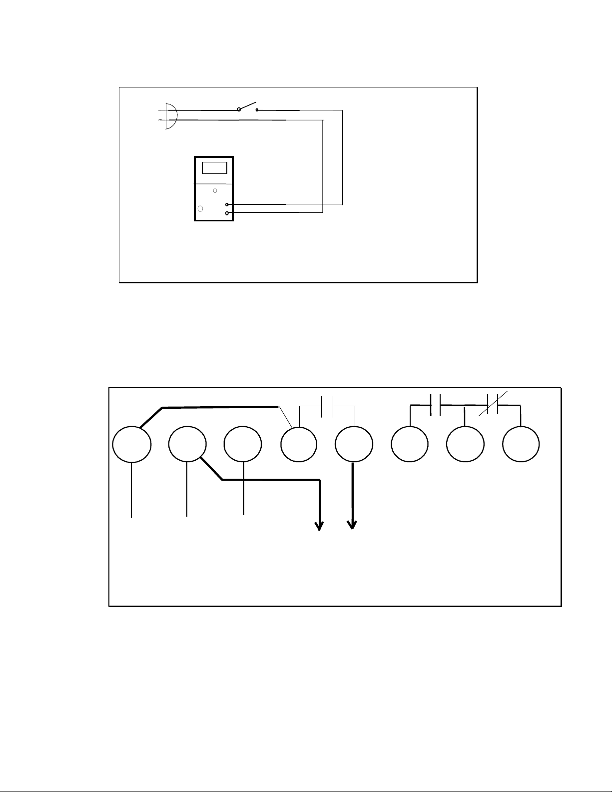
AC Input
Connect the two test leads to the two input jacks on the front of the instrument. Since the instrument
counts AC pulses, the AC line must be switched by the relay that is in the timer under test. A typical
wiring configuration is shown in schematic form in Figure 1. A typical wiring configuration for testing an
Electronic Control Concepts Model 8200A Timer is shown in Figure 2.
The circuit for AC inputs is completely isolated from the rest of the instrument. No damage to the
instrument will occur if the probes are reversed. However, to obtain the best accuracy, the '+' (Red)
should be connected to the high side of the line, and the black or '-' probe should be connected to the low
side of the line.
Oscilloscope Output

A jack is available at the left side of the instrument to observe x-ray waveforms. When looking at the
Model 07-453 from the left, the connector labeled ‘SCOPE’ the Oscilloscope output. This connector takes
a standard 2.5mm mono phone plug.
Model 07-453 Connection to Model 8200A Timer
Blk Wht Grn
AC LINE
1234678
TO 8700
RED
BLK
ADD JUMPER
FIGURE 2
5
Red
Black
Relay
07-453 Figure 1
Wiring for AC
Pl
Measurment

Section 3
Battery Replacement
Oscilloscope Output
BATTERY REPLACEMENT
The Model 07-453 is supplied with one 9 Volt Alkaline battery. Replace the battery when the "Lo Bat"
indicator shows in the display. Any standard 9 Volt Alkaline battery can be used in the 07-453. To meet
the battery life specification, please use a Duracell MN1604 Battery. This is the familiar “gold top” battery.
To prolong battery life, turn the instrument off when not in use.
To replace the battery, slide the battery compartment open on the bottom of the case. Remove the old
battery, and install the new battery.
OSCILLOSCOPE OUTPUT
The 07-453 can be and usually is used without an oscilloscope, but the scope output feature enables
technical analysis of the x-ray output.
X-ray generators often have characteristics such as gradual rise times, variations in amplitude, noise,
capacitive filtering, and extended decay times. Problems with x-rays can often be diagnosed by
observing the output waveform of an x-ray with an oscilloscope. A jack is provided on the left side of the
07-453 case to enable a user to observe the x-ray wave form on an oscilloscope. Plug in a standard
2.5mm mono phone plug into the jack and attach the leads of the scope probe to the phone plug
terminals. Set the vertical sensitivity of the scope to about 0.2 Volt per cm. The scope waveform will be
an amplified version of the actual output of the x-ray detector.
A cable with a phone plug and a BNC connector for a scope is available from Fluke Biomedical. Order
Fluke Biomedical Part Number 07-453SC. Alternatively, a 2.5mm mono phone plug is available from
many vendors including Mouser Electronics, Part No. 177PP095. An oscilloscope probe can be clipped
to this part.
The Remote Sensor available from Fluke Biomedical is particularly useful when observing the x-ray
output using an oscilloscope. Order Fluke Biomedical Part Number 07-453RS.
(Blank page)


Section 4
Calibration and
Exposure Time Conversion
Chart
CALIBRATION
The circuitry in the Model 07-453 (above serial number 1001) is completely digital and microprocessor
controlled and will not need periodic calibration. As a service Fluke Biomedical will continue to test, verify
and issue a calibration certificate for all instruments upon customer request.
EXPOSURE TIME CONVERSION CHART
Impulses Time
in Seconds Time
in Seconds Time
in Seconds
10.02 0.02 0.01
20.03 0.04 0.02
30.05 0.06 0.03
40.07 0.08 0.03
50.08 0.1 0.04
60.1 0.12 0.05
70.12 0.14 0.06
80.13 0.16 0.07
90.15 0.18 0.08
10 0.17 0.2 0.08
15 0.25 0.3 0.13
20 0.33 0.4 0.17
25 0.42 0.5 0.21
30 0.5 0.6 0.25
35 0.58 0.7 0.29
40 0.67 0.8 0.33
45 0.75 0.9 0.38
50 0.83 10.42
60 11.2 0.5
70 1.17 1.4 0.58
80 1.33 1.6 0.67
90 1.5 1.8 0.75
100 1.67 20.83
120 22.4 1
150 2.5 31.25
180 33.6 1.5
200 3.33 41.67
240 44.8 2
60 Hz Line 50 Hz Line Full Wave

USA, Canada Europe @ 60 Hz

(Blank page)

Section 5
Warranty and
Service Information
WARRANTY
Fluke Biomedical warrants the Model 07-453 X-ray Timer/Counter from defects in
materials and workmanship for a period of one year. There is no warranty on the
battery. Fluke Biomedical will replace or repair any Model 07-453 during the first two
years after shipment that does not show obvious signs of abuse. Contact the factory as
described below.
SERVICE INFORMATION
If a unit should need calibration or service, please contact the factory by phone or fax to
obtain a Service Return Authorization (SRA).
(440)542-3682 Fax
After obtaining an SRA number
ship the unit to:
Fluke Biomedical
6045 Cochran Road
Cleveland, OH 44139

(Blank page)

Section 6
Specifications
Model 07-453 SPECIFICATIONS
Accuracy
•AC Input / X-ray Pulse - +/- 1 Count
•DC Input - 2% +/- 1 Count
oMeasures at 70% of peak value
Sensitivity
•AC Input - 90 VAC minimum
•X-ray input - 50kVp, 5mA at 2.0 inches from top surface of case, pointed to target on case.
Range
•9999 Pulses
•9999 Milliseconds
Display
•0.3" Liquid Crystal
Power
•9 Volt Battery
Low Battery Indicator
•"Lo Batt" Appears in display when battery voltage reaches 5.3 Volts +/- 0.3 Volt.
Size
•80 X 147 X 40 mm
•3.15 X 5.8 X 1.6 inches
Battery Life
•48 Hours minimum
oWith Duracell MN1604 Alkaline or equivalent
AC Input Jacks
•130 Volts AC maximum
•90 Volts AC minimum
•Input circuit not affected by reversed polarity
Optional Accessories
•Remote x-ray sensor
•Carrying case
•AC test leads with tip plugs

(Blank page)
Section 7

Appendix
APPENDIX
X-RAY WAVEFORMS
This section has been added to the manual to assist users of the Fluke Biomedical Model 07-453 Pulse
Counter / Exposure Time Meter. Understanding the material in this section will enable the user to obtain
the correct exposure time for any x-ray.
HALF-WAVE – This is typical of practically all dental x-rays and most podiatry x-rays.
Switch the Model 07-453 to PULSE. The instrument will count and display the number of pulses. To
convert to time (in seconds), refer to the Exposure Time Conversion Chart or use the formula Time =
pulses / 60 (in countries with 60 Hz power). As shown, the 07-453 would count 6 pulses, and the
exposure time would be 6/60 = 0.1 second.
FULL-WAVE – This is typical of some older hospital x-rays.
Switch the Model 07-453 to PULSE. The instrument will count and display the number of pulses. To
convert to time (in seconds), refer to the Exposure Time Conversion Chart or use the formula Time =
pulses / 120 (in countries with 60 Hz power). As shown, the 07-453 would count 12 pulses, and the
exposure time would be 12/120 = 0.1 second.

DC X-RAYS
This type of x-ray is typical of the larger x-rays and is multi-phase or 3 phase. A drawing of a typical
waveform is shown below. A very similar waveform is also produced by capacitor discharge x-rays.
These are portable, battery operated x-rays.
Switch the Model 07-453 to MILLISEC. Take the x-ray exposure. The instrument will count and display
the exposure time in milliseconds. For example if the x-ray is set for 2/10 second, the actual exposure
time should be around 200 milliseconds.
It is important to note that the 07-453 will end the count at the end of the x-ray when the intensity drops
below about 70% of the peak value. This is done to ensure an accurate count when there is a ”tail” at the
end of the x-ray i.e. the x-ray intensity drops slowly.
If the Model 07-453 is in PULSE mode, and a measurement of a DC or multiphase x-ray is taken the
instrument will count and display 1. This is because the 07-453 detects what is basically one pulse.
Switch the instrument to MILLISEC and take another exposure.

Other manuals for Nuclear Associates 07-453
1
Table of contents
Other Fluke Measuring Instrument manuals

Fluke
Fluke 1587 User manual

Fluke
Fluke 917 Series User manual

Fluke
Fluke IntelliTone Pro 200 LAN User manual

Fluke
Fluke OptiView III Series User manual

Fluke
Fluke v3000 FC Use and care manual

Fluke
Fluke FindFiber Source User manual

Fluke
Fluke 715 User manual

Fluke
Fluke 3014-PR User manual

Fluke
Fluke 635 User manual

Fluke
Fluke ScopeMeter 123 User manual

Fluke
Fluke 971 User manual

Fluke
Fluke ProcessMeter 787 User manual

Fluke
Fluke 753 User manual

Fluke
Fluke 374 FC User manual

Fluke
Fluke 5790B/3 User manual

Fluke
Fluke 1630-2 Use and care manual

Fluke
Fluke 5790A User manual

Fluke
Fluke 433 User manual

Fluke
Fluke 96000 Series User manual

Fluke
Fluke 930 User manual