Troubleshooting
Fault Possible cause Solution
Lid failing
to close
Guideway
obstructed.
Spring failure.
Examing the guideway and remove any
obstruction.
Examine the springs and ensure that they
are connected to the respective holding
pins within the assembly.
If a spring has failed, or is missing, spring
replacement kits are available from your
local Renishaw company or supplier.
Alternatively, return the unit to your local
Renishaw service centre to have new
springs fitted.
Failure to
complete
a stylus
change
Incorrect
alignment.
Re-align the MRS rail (refer to the MRS
modular rack system installation and
user’s guide, Renishaw part number
H-1000-5088).
Redatum the SCP600 port.
Accessories / spare parts
SCP600 port (includes tooling) A-2098-0933
T nut P-NU18-0005
Stylus spanner M-5000-3707
Put down and pick up routines
NOTE: The following section assumes that the datum created in ‘Datuming
the SCP600’ earlier in this document is the axis system in which the machine
is working.
Put down routine
The following table lists the recommended procedure for putting down a
stylus module on the SCP600. All dimensions are absolute and given in mm.
Operation Axis position
X axis Y axis Z axis
Inhibit the probe
Move to stand-off position 0 50 0
Move into port 0 0 0
Detach stylus module 0 0 8
Move to stand-off position 0 50 8
Pick up routine
The following table lists the recommended procedure for picking up a stylus
module from the SCP600. All dimensions are absolute and given in mm.
Operation Axis position
X axis Y axis Z axis
Move to stand-off position 0 50 8
Move into port 0 0 8
Attach stylus module 0 0 0
Move to stand-off position 0 50 0
Activate probe
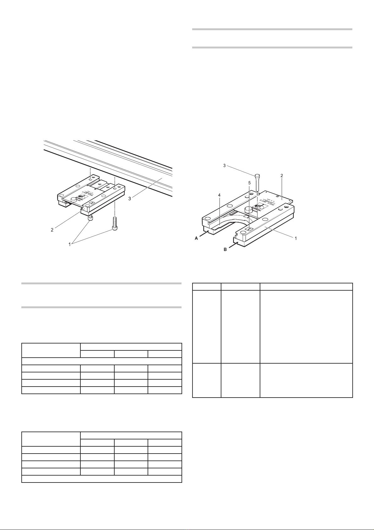
1. Fixing screw
2. SCP600 port
3. MRS rail
Figure 2 - Fitting a SCP600 port to the MRS rail
Datuming the SCP600
NOTE: As the SCP600 port is of modular design, it is suggested that the
following routine is completed under manual control for each port installed.
The following section describes the recommended procedure for datuming
the SCP600 once it is fitted to the MRS rail and on the CMM table. In
addition, the following method assumes that the SCP600 port is aligned to
the CMMs axis with a maximum run out of 2.5 mm across points A and B
(see figure 3). If required, please refer to ‘Fitting the SCP600 to the MRS rail’
earlier in this document. The recommended procedure to locate the port is
as given below (please refer to figure 3):
1. Push the lid [2] of the SCP600 port [1] to the extreme of travel (this
assumes that the SCP600 is connected to the MRS system at the time).
2. Place the stylus tool [3] into the retaining hole at the rear of the
SCP600 port [1].
3. Release the SCP600 lid [2] so that the stylus tool [3] holds the lid.
4. Take 4 points on the top face of the docking plate [4] (plane 1).
5. Take 4 points in the circle at the rear of the SCP600 port docking
plate [4] (circle 1).
Figure 3 - Datuming the SCP600 port
1. SCP600
2. Lid
3. Stylus tool
4. Docking plate
5. Port
identification
label
Fitting the SCP600 to the MRS rail
It is recommended that the SCP600 ports are attached to the MRS rail using
the following procedure where it is assumed that the MRS system is correctly
installed. For full details, please refer to the MRS modular rack system
installation and user’s guide (H-1000-5088):
1. Insert one of the fixing screws [1] through the SCP600 port [2] as
shown in figure 2.
2. Offer up the SCP600 port [2] to the MRS rail [3], positioning the fixing
screw [1] to the respective ‘T’ bolt within the rail. Finger-tighten the
screw.
3. Insert the other fixing screw [1] through the SCP600 port [2] as shown
in figure 2.
4. Position the SCP600 port so that the second screw locates into the
respective ‘T’ bolt in the rail. Finger-tighten the screw.
5. Using the hexagonal key supplied, hand-tighten the two fixing screws
[1] into the ‘T’ bolts.


