Fluke 175 Use and care manual

®
PN 1600476 March 2001 Rev.2, 12/02
© 2001-2002 Fluke Corporation. All rights reserved. Printed in U.S.A. 1
175, 177, & 179
True RMS Multimeters
Calibration Information
Introduction
WWarning
To avoid electric shock or injury, do not perform the performance tests or
calibration procedures unless you are qualified to do so.
The information provided in this manual is for the use of qualified personnel
only.
The 175, 177, & 179 Calibration Information provides the information necessary to calibrate and verify
the performance of the Fluke Models 175, 177, and 179 True RMS Multimeters (hereafter known as the
Meter).
The following information is included in this document:
•Safety Information and International Electrical Symbols (page 2)
•Test Lead Alert (page 3)
•Specifications (pages 3-6)
•Testing and Replacing the Fuses (pages 6-7)
•Replacing the Battery (page 7-8)
•Cleaning (page 8)
•Replacing the LCD (page 9)
•Performance Tests (pages 10-13)
•Calibration (page 14-16)
•User-Replaceable Parts and Accessories (page 17-18)
•Warranty Statement (page 19)
See the 175, 177, & 179 Users Manual for complete operating instructions.
Service Information
To contact Fluke, call:
1-888-99-FLUKE (1-888-993-5853) in USA
1-800-36-FLUKE (1-800-363-5853) in Canada
+31 402-678-200 in Europe
+81-3-3434-0181 Japan
+65-276-6196 Singapore
+1-425-446-5500 in other countries
For additional information about Fluke, its products, and services, visit Fluke’s web site at:
www.fluke.com
To register this product, go to register.fluke.com

175, 177, & 179
Calibration Information
2
Safety Information
WWarnings and Precautions
To avoid possible electric shock or personal injury, and to avoid possible damage to the Meter
or to the equipment under test, adhere to the following practices:
•Before using the Meter, inspect the case. Do not use the Meter if it is damaged. Look for
cracks or missing plastic. Pay particular attention to the insulation around the connectors.
•Inspect the test leads for damaged insulation or exposed metal. Check the test leads for
continuity. Replace damaged test leads before using the Meter.
•Verify the Meter’s operation by measuring a known voltage. Do not use the Meter if it
operates abnormally. Protection may be impaired. When in doubt, have the Meter serviced.
•Do not apply more than the rated voltage, as marked on the Meter, between the terminals or
between any terminal and earth ground.
•Use caution when working with voltages above 30 V ac rms, 42 V ac peak, or 60 V dc. These
voltages pose a shock hazard.
•Use the proper terminals, function, and range for your measurements.
•Do not operate the Meter around explosive gas, vapor, or dust.
•When using the probes, keep your fingers behind the finger guards.
•When making connections, connect the common test lead before connecting the live test
lead; when disconnecting, disconnect the live test lead before disconnecting the common
test lead.
•Disconnect circuit power and discharge all high-voltage capacitors before testing resistance,
continuity, diodes, or capacitance.
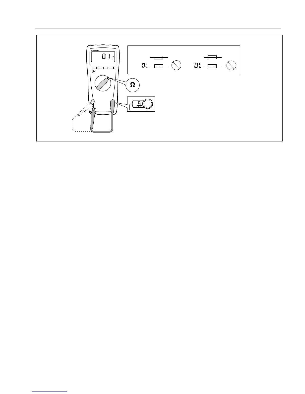
•Before measuring current, check the Meter's fuses (see "Testing the Fuses") and turn OFF
power to the circuit before connecting the Meter to the circuit.
•Do not operate the Meter with the case (or part of the case) removed.
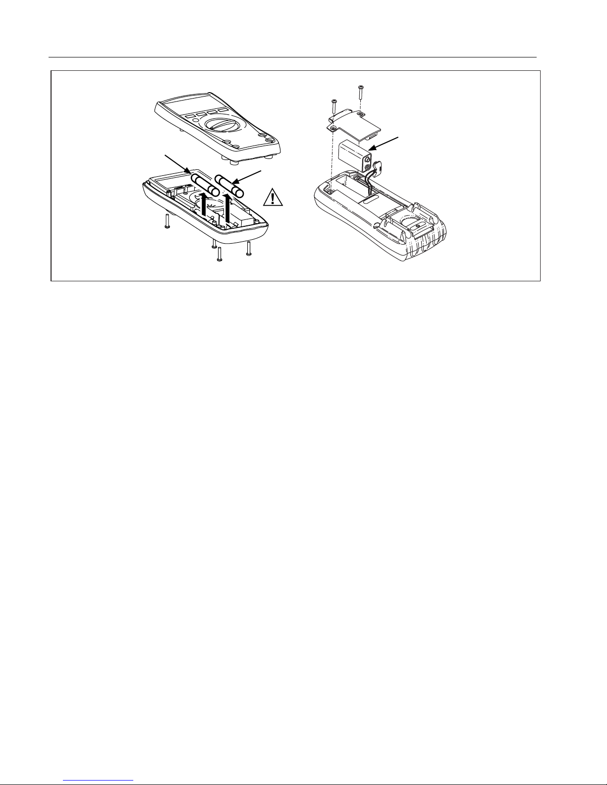
•Use only a single 9 V battery, properly installed in the Meter case, to power the Meter.
•Replace the battery as soon as the low battery indicator (b) appears. With a low battery, the
Meter might produce false readings that can lead to electric shock and personal injury.
•Remove test leads from the Meter before opening the Meter case.
•When servicing the Meter, use only specified replacement parts.
•When replacing the fuses, use ONLY replacement fuses with the amperage, interrupt,
voltage, and speed ratings specified in Table 5.
International Electrical Symbols
The following international symbols appear in this document and on the Meter.
AC (Alternating Current) Earth ground
DC (Direct Current) Fuse
AC or DC Conforms to European Union directives
Important Information. Refer to the
manual. Conforms to relevant Canadian Standards
Association directives
bBattery Double insulated
Confroms to VDE Standards

True RMS Multimeters
Test Lead Alert
3
Test Lead Alert
WWarning
Personal injury or damage to the Meter can occur if you attempt to make a
measurement with a lead in an incorrect terminal.
To remind you to check that the test leads are in the correct terminals, LEAd is displayed when the rotary
switch is moved to or from any Aposition.
Specifications
General Specifications
Accuracy is specified for 1 year after calibration, at operating temperatures of 18 °C to 28 °C, with relative humidity
at 0 % to 75 %. Accuracy specifications take the form of: ±( [ % of Reading ] + [ Counts ] ). AC conversions are
ac-coupled, average responding, and calibrated to the rms value of a sine wave input.
Maximum voltage between
any terminal and earth ground: 1000 V DC or AC RMS
Surge Protection: 8 kV peak per IEC 61010
WFuse for mA inputs:
WFuse for A input:
440 mA, 1000 V FAST Fuse, minimum interrupt rating 10 kA
11 A, 1000 V FAST Fuse, minimum interrupt rating 17 kA
Display: Digital: 6000 counts, updates 4/sec
Bar Graph: 33 segments;
Updates 40/sec
Frequency: 10,000 counts
Capacitance: 1,000 counts
Altitude: Operating: 2000 m; Storage: 12,000 m
Temperature: Operating: −10 °C to +50 °C;
Storage: −30 °C to +60 °C
Temperature coefficient: 0.1 X (specified accuracy / °C
(< 18 °C or > 28 °C)
Electromagnetic Compatibility
(EN 61326-1:1997): In an RF field of 3 V/M, accuracy = specified accuracy except in temperature:
specified accuracy ±5 °C (9 °F)
Relative Humidity:
Relative Humidity in
50 MΩRange:
0 % to 90 % @ 0 °C to 35 °C;
0 % to 70 % @ 36 °C to 50 °C
0 % to 80 % @ 0°C to 35 °C;
0 % to 70 % @ 36 °C to 50 °C
Battery Life: Alkaline: ~200 hrs typical
Size (H x W x L): 4.3 cm x 9 cm x 18.5 cm
Weight: 420 g
Safety Compliances: ANSI/ISA S82.02.01, CSA C22.2-1010.1, IEC 61010 to 1000 V Overvoltage
Category III, 600 V Overvoltage Category IV
CAT III- Equipment designed to protect against transients in equipment in fixed-
equipment installations, such as distribution panels, feeders and short branch
circuits, and lighting systems in large buildings.
CAT IV- Equipment designed to protect user against transients from the primary
supply level, such as an electricity meter or an overhead or underground utility
service.
Certifications: CSA, TÜV (EN61010), P, ;(N10140), UL (3111), VDE

175, 177, & 179
Calibration Information
4
Accuracy ± ( [ % of Reading ] + [ Counts ] )
Function Range 1Resolution Model 175 Model 177 Model 179
AC Volts 2600.0 mV
6.000 V
60.00 V
600.0 V
1000 V
0.1 mV
0.001 V
0.01 V
0.1 V
1 V
1.0 % + 3
(45 Hz to 500 Hz)
2.0 % + 3
(500 Hz to 1 kHz)
1.0 % + 3
(45 Hz to 500 Hz)
2.0 % + 3
(500 Hz to 1 kHz)
1.0 % + 3
(45 Hz to 500 Hz)
2.0 % + 3
(500 Hz to 1 kHz)
DC mV 600.0 mV 0.1 mV 0.15 % + 2 0.09 % + 2 0.09 % + 2
DC Volts
6.000 V
60.00 V
600.0 V
0.001 V
0.01 V
0.1 V 0.15 % + 2 0.09 % + 2 0.09 % + 2
1000 V 1 V 0.15 % + 2 0.15 % + 2 0.15 % + 2
Continuity 600 Ω1 ΩMeter beeps at < 25 Ω, beeper turns off at > 250 Ω; detects
opens or shorts of 250 µs or longer.
Ohms 600.0 Ω
6.000 kΩ
60.00 kΩ
600.0 kΩ
6.000 MΩ
50.00 MΩ
0.1 Ω
0.001 kΩ
0.01 kΩ
0.1 kΩ
0.001 MΩ
0.01 MΩ
0.9 % + 2
0.9 % + 1
0.9 % + 1
0.9 % + 1
0.9 % + 1
1.5 % + 3
0.9 % + 2
0.9 % + 1
0.9 % + 1
0.9 % + 1
0.9 % + 1
1.5 % + 3
0.9 % + 2
0.9 % + 1
0.9 % + 1
0.9 % + 1
0.9 % + 1
1.5 % + 3
Diode test 2.400 V 0.001 V 1 % + 2
Capacitance 1000 nF
10.00 µF
100.0 µF
9999 µF 3
1 nF
0.01 µF
0.1 µF
1 µF
1.2 % + 2
1.2 % + 2
1.2 % + 2
10 % typical
1.2 % + 2
1.2 % + 2
1.2 % + 2
10 % typical
1.2 % + 2
1.2 % + 2
1.2 % + 2
10 % typical
AC Amps
(True RMS)
(45 Hz to 1 kHz)
60.00 mA
400.0 mA
(600 mA for 18 hrs)
6.000 A
10.00 A
(20 A for 30 s)
0.01 mA
0.1 mA
0.001 A
0.01 A
1.5 % + 3 1.5 % + 3 1.5 % + 3
1. All AC voltage and AC current ranges are specified from 5 % of range to 100 % of range.
2. Crest factor of ≤3 at full scale up to 500 V, decreasing linearly to crest factor ≤1.5 at 1000 V.
3. In the 9999 µF range for measurements to 1000 µF, the measurement accuracy is 1.2 % for all models.

True RMS Multimeters
Specifications
5
Accuracy ± ( [ % of Reading ] + [ Counts ] )
Function Range 1Resolution Model 175 Model 177 Model 179
DC Amps 60 mA
400.0 mA (600 mA for 18 hrs)
6.000 A
10.00 A (20 A for 30 s)
0.01 mA
0.1 mA
0.001 A
0.01 A
1.0 % + 3 1.0 % + 3 1.0 % + 3
Hz
(AC- or DC-
coupled,
V or A 2, 3, 4 input )
99.99 Hz
999.9 Hz
9.999 kHz
99.99 kHz
0.01 Hz
0.1 Hz
0.001 kHz
0.01 kHz
0.1 % + 1 0.1 % + 1 0.1 % + 1
Temperature −40 °C to +400 °C
−40 °F to +752 °F0.1 °C
0.1 °FNA NA 1 % + 10
1 % + 18
MIN MAX AVG For DC functions, accuracy is the specification of the measurement function ±12 counts for changes
longer than 275 ms in duration.
For AC functions, accuracy is the specification of the measurement function ±40 counts for changes
longer than 1.2 s in duration.
1. All AC voltage and AC current ranges are specified from 5 % of range to 100 % of range.
2. Frequency is specified from 2 Hz to 99.99 kHz in Volts and from 2 Hz to 30 kHz in Amps.
3. Frequency < 10 kHz are not specified in 600 mV AC, 60 mA AC, and 6 A AC ranges.
4. Below 2 Hz, the display shows 0 Hz.
Function Overload
Protection *
Input
Impedance
(Nominal)
Common Mode Rejection
Ratio
(1 kΩUnbalanced) Normal Mode
Rejection
Volts AC 1000 V RMS or DC > 10 MΩ< 100 pF > 60 dB @ DC, 50 or 60 Hz
Volts DC 1000 V RMS or DC > 10 MΩ< 100 pF >120 dB @ DC, 50 or 60 Hz > 60 dB @ 50 Hz or 60 Hz
Open Circuit
Test Voltage Full Scale Voltage To:
6.0 MΩ50 MΩShort Circuit Current
Ohms 1000V RMS or DC < 1.5 V DC < 600 mV DC < 1.5 V DC < 500 µA
Diode test 1000V RMS or DC 2.4 to 3.0 V DC 2.4 V DC < 1.2 mA typical
* 107 V-Hz maximum.

175, 177, & 179
Calibration Information
6
Frequency Counter Sensitivity
Typical Sensitivity (RMS Sine Wave)
Input Range 1, 2 2 Hz to 45 Hz 45 Hz to
10 kHz 10 kHz to
20 kHz 20 kHz to
50 kHz 50 kHz to
100 kHz
Volts AC 600 mV Unspecified 380 mV 150 mV 400 mV Unspecified 3
6 V 0.5 V 0.6 V 1.0 V 2.8 V Unspecified 3
60 V 5 V 3.8 V 4.1 V 5.6 V 9.6 V
600 V 50 V 36 V 39 V 45 V 58 V
1000 V 500 300 V 320 V 380 V NA
Volts DC 6 V 0.5 V 0.75 V 1.4 V 4.0 V Unspecified 3
60 V 4 V 3.8 V 4.3 V 6.6 V 13 V
600 V 40 V 36 V 39 V 45 V 58 V
1000 V 500 V 300 V 320 V 380 V NA
AC/DC Amps mA 5 mA 4 mA 4 mA 4 mA 4NA
A 0.5 A 0.4 A 0.4 A 0.4 A 4NA
1. Maximum input for specified accuracy = 10 x Range or 1000 V.
2. Noise at low frequency and amplitude may exceed the frequency accuracy specification.
3. Unspecified but usable depending on quality and amplitude of signal.
4. In mA and A ranges, frequency measurement is specified to 30 kHz.
Testing the Fuses
WWarning
To avoid electrical shock or personal injury:
•Remove the test leads and any input signals before replacing the battery or
fuses.
•To avoid electrical shock, arc blast, or damage to the Meter, install only
fuses with the amperage, interrupt, and voltage, and speed ratings specified
in Table 5.
To test the fuses (refer to Figure 1):
1. Set the rotary switch to e.
2. Plug a test lead into the VeG terminal and touch the probe to the 400 mA (to test the 440 mA fuse)
or 10 A terminal (to test the 11 A fuse).
•If the display shows a resistance value in the range shown in Figure 1, the fuse is good.
•If the display reads OL, replace the fuse and test again.
•If the display shows any other value have the Meter serviced. See “Service Information” earlier in
this manual.

True RMS Multimeters
Replacing the Fuses
7
11 A440 mA Ω
<.5
Ω
<12 OKOK
OK
OK
RANGEHOLD
MINMAX
V
aik12f.eps
Figure 1. Testing the Current Fuses
Replacing the Fuses
WWarning
To avoid electrical shock, arc blast, or damage to the Meter, install only fuses
with the amperage, interrupt, and voltage, and speed ratings specified in
Table 5.
To replace the fuses (refer to Figure 2):
1. Turn the rotary switch to OFF.
2. Disconnect the test leads and/or any connectors from the terminals.
3. Remove the four screws from the case bottom, and separate the case top from the case bottom.
4. Remove the fuses by gently prying one end loose, then slide the fuse out of its bracket, and replace
with a properly rated good fuse.
5. Rejoin the case bottom and case top, and reinstall the four screws.
Replacing the Battery
WWarning
To avoid false readings, which could lead to possible electric shock or personal
injury, replace the battery as soon as the low battery indicator ( b) appears.
To replace the battery (refer to Figure 2):
1. Turn the rotary switch to OFF and remove the test leads from the terminals.
2. Remove the two screws from the battery compartment door, and remove it from the case bottom.
3. Remove the battery from the battery connector.
4. Replace the battery with a new 9 V battery (NEDA A1604, 6F22, or 006P).
5. Reattach the battery compartment door to the case bottom and reinstall the two screws.

175, 177, & 179
Calibration Information
8
F2
F1
B1
aik13f.eps
Figure 2. Battery and Fuse Replacement
Cleaning
WWarning
To avoid electrical shock:
•Remove test leads and any input signals before cleaning
•Do not reinstall the pca until it is completely dry
Dirt or moisture in the terminals can affect readings
Caution
To avoid damaging the Meter, do not use aromatic hydrocarbons or chlorinated
solvents for cleaning. These solutions will react with the plastics used in the
instruments.
Do not use detergents of any kind for cleaning the pca.
Clean the instrument case with a damp cloth and mild detergent.
The pca may be washed with isopropyl alcohol or hot deionized water and a soft brush. Remove excess
cleaning material with clean dry air at low pressure, then dry the pca at 50 °C.

True RMS Multimeters
Replacing the LCD
9
Replacing the LCD
Caution
To prevent contamination, do not handle the conductive edges of the LCD or
LCD interconnects.
If the edges are contaminated, clean them with alcohol. Allow the alcohol to dry
before reassembling.
To remove and replace the LCD, perform the following procedure. Refer to Figure 3.
1. Turn the rotary switch to OFF and remove test leads from the Meter terminals.
2. Remove the four screws from the case bottom, and separate the case top from the case bottom.
The circuit board remains attached to the case bottom.
3. Disconnect the battery from the battery leads.
4. Remove the circuit board screw located under the 440 mA fuse, and lift the circuit board out of the
bottom case.
5. Loosen the 4 screws on the back of the pca. This will facilitate reinstalling the LCD.
6. Insert a small, flat-head screwdriver under the LCD mask edge and gently pry the mask from the
snaps.
Caution
To avoid damaging the Meter, take care to not break the LCD with the
screwdriver.
7. Lift out the LCD.
8. Make sure that all connector contact points are clean. Refer to “Cleaning” for more information.
9. Install a new LCD, taking care that it is correctly oriented.
10. Reattach the LCD mask to the LCD assembly by snapping the mask into place.
11. Tighten the 4 screws on the back of the pca.
12. Lay the circuit board back into the bottom case, and screw it down.
13. Reinsert the 440 mA fuse.
14. Reinstall the battery.
15. Rejoin the case bottom and case top, and reinstall the four case screws.
LCD Mask
aik15f.eps
Figure 3. Removing the LCD Mask

175, 177, & 179
Calibration Information
10
Performance Tests
WWarning
To avoid electric shock, do not perform the performance test procedures unless
the Meter is fully assembled.
The following performance tests verify the complete operation of the Meter and check the accuracy of
each meter function against the Meter’s specifications. If the Meter fails any part of the test, calibration
adjustment and/or repair is indicated.
In the performance tests, the Meter is referred to as the unit under test (UUT).
Required Equipment
A Fluke 5500A Multi-Product Calibrator (or equivalent) is required for the performance test procedures
in this document.
If an equivalent calibrator is used, it must meet the accuracy specifications shown in Table 1.
Table 1. Calibrator Specifications
Recommended Equipment Measurement Function Accuracy
5500A Multi-Product Calibrator
(or equivalent) DC Volts 0 to 1000 V
±0.075 %
DC Current 0 to 10 A
±0.425 %
AC Volts 0 to 1000 V
±0.375 % @ 45 Hz to 1 kHz
AC Current 0 to 10 A
±0.55 %
Resistance 0 to 4 MΩ
±0.125 %
4 to 40 MΩ
±0.5 %
Capacitance 500 pF to 5 µF
±0.325 %
Temperature .25%
Frequency 0.5 Hz to 100 kHz
±0.005 %
Fluke 80 AK
Thermocouple Adapter Accessory K-type -
K-type Thermocouple K-type, mini-plug on both ends -

True RMS Multimeters
Performance Tests
11
Preparing for the Performance Test
WWarning
To avoid possible electric shock or personal injury:
•Do not perform the following procedures unless qualified to do so. Some
procedures involve the use of high voltages.
•Before handling the test connections and in between tests, make sure the
calibrator is in standby mode (STBY).
To prepare for the performance test:
1. Make sure that you have the required equipment, see Table 1.
2. Warm up the calibrator as required by its specifications.
3. Allow the temperature of the UUT to stabilize at room temperature ( 23 °C ±5 °C [73 °F ±9 °F] ).
4. Check the fuses and battery, and replace them if necessary. Refer to "Replacing the Fuses" and
"Replacing the Battery".
Performance Tests
1. Set the UUT switch to the position called for in Table 2 (175) or Table 3 (177/179), and for all
measurements other than current (amps), connect the calibrator to the VeG and COM input
terminals.
•If testing the milliamps function, connect the calibrator to the meter 400 mA and COM input
terminals.
•If testing the amps function, connect the calibrator to the meter 10A and COM input terminals.
2. Referring to Table 2 or Table 3, apply the indicated calibrator output voltages to the UUT for each
test.
3. Verify that the UUT displays a reading that is within the limits shown in the Meter Response column.
Table 2. Performance Tests 175
Meter Response
Test
(Switch Position) 5520 Output Lower Limit Upper Limit
300 mV 45 Hz 296.7 mV AC 303.3 mV AC
5 V 500 Hz 4.947 V AC 5.053 V AC
5 V 1 kHz 4.897 V AC 5.103 V AC
50 V 1 kHz 48.97 V AC 51.03 V AC
50 V 45 Hz 49.47 V AC 50.53 V AC
300 V 45 Hz 296.7 V AC 303.3 V AC
100 V 500 Hz 98.7 V AC 101.3 V AC
100 V 1 kHz 97.7 V AC 102.3 V AC
600 V 500 Hz 593.7 V AC 606.3 V AC
K
AC Volts
1000 V 45 Hz 987 V AC 1013 V AC

175, 177, & 179
Calibration Information
12
Table 2. Performance Tests 175 (continued)
Meter Response
Test
(Switch
Position) 5520 Output Lower Limit Upper Limit
3 V 2.993 V DC 3.007 V DC
300 V 299.3 V DC 300.7 V DC
1000 V 996 V DC 1004 V DC
L
DC Volts
−1000 V −1004 V DC −996 V DC
1 V 45 Hz 44.94 Hz 45.06 Hz
1 V 2 kHz 1.997 kHz 2.003 kHz
1.5 V 20 kHz 19.97 kHz 20.03 kHz
* Hz
Frequency
5 V 50 kHz 49.94 kHz 50.06 kHz
0.03 V 0 Hz 29.8 mV DC 30.2 mV DC
-0.3 V −300.7 mV DC −299.3 mV DC
0.6 V 598.9 mV DC 601.1 mV DC
1.5 V 20 kHz 19.97 kHz 20.03 kHz
E
Millivolts DC
5 V 50 kHz 49.94 kHz 50.06 kHz
25 ΩBeeper OnR
Continuity 250 ΩBeeper Off
19 Ω18.6 Ω19.4 Ωe
Ohms219000000 Ω18.68 MΩ19.32 MΩ
G
Diode1Apply 2.0 V 1.978 V DC 2.022 V DC
E
Capacitance1Apply 0.90 uF 887 nF 913 nF
4.0 A 45 Hz 3.937 A AC 4.063 A AC?
Amps AC 9.0 A 1 kHz 8.83 A AC 9.17 A AC
0.003 A 45 Hz 2.92 mA AC 3.08 mA AC
0.05 A 1 kHz 49.22 mA AC 50.78 mA AC
F
AC Milliamps
0.4 A 1 kHz 393.7 mA AC 406.3 mA AC
0.003 A, 0 Hz 2.94 mA DC 3.06 mA DC
0.05 A 49.47 mA DC 50.53 mA DC
mI
DC Milliamp1
0.4 A −404.3 mA DC −395.7 mA DC
4.0 A 3.957 A DC 4.043 A DCA
DC Amps1−9.0 A −9.12 A DC −8.88 A DC
1. Press the YELLOW button to access this function.
2. Does not include test lead resistance.

True RMS Multimeters
Performance Tests
13
Table 3. Performance Tests 177/179
Meter Response
Test 5520 Output Lower Limit Upper Limit
300 mV 45 Hz 296.7 mV AC 303.3 mV AC
5 V 500 Hz 4.947 V AC 5.053 V AC
5 V 1 kHz 4.897 V AC 5.103 V AC
50 V 45 Hz 49.47 V AC 50.53 V AC
50 V 1 kHz 48.97 V AC 51.03 V AC
100 V 1 kHz 97.7 V AC 102.3 V AC
300 V 45 Hz 296.7 V AC 303.3 V AC
600 V 1 kHz 587.7 V AC 612.3 V AC
K
AC Volts
1000 V 45 Hz 987 V AC 1013 V AC
5 V 4.993 V DC 5.007 V DC
300 V 299.6 V DC 300.4 V DC
1000 V 997 V DC 1003 V DC
L
DC Volts
−1000 V −1003 V DC −997 V DC
1.5 V 20 kHz 19.97 kHz 20.03 kHz* Hz
Frequency 5 V 50 kHz 49.95 kHz 50.05 kHz
0.03 V 0 Hz 29.8 mV DC 30.2 mV DC
-0.3 V −300.4 mV DC −299.6 mV DC
E
Millivolts DC
0.6 V 599.3 mV DC 600.7 mV DC
19 Ω18.6 Ω19.4 Ωe
Ohms319000000 Ω18.69 M Ω19.31 M Ω
25 ΩBeeper OnR
Continuity3250 ΩBeeper Off
0 °C−1.0 °C1.0°C
-40 °C−41.4 °C−38.6 °C
T
Temperature1,3,4
(179 only) 400 °C 395.0 °C 405.0 °C
O
Diode12.0 V 1.978 V DC 2.022 V DC
N
Capacitance10.90 uF 887 nF 913 nF
1. Press the YELLOW button to select this function.
2. Does not include test lead resistance.
3. Be sure to use correct cable.
4. To ensure accuracy, the Meter and thermocouple adapter must be at the same temperature. Allow 20 minutes before performing
the temperature procedures.

175, 177, & 179
Calibration Information
14
Table 4. Performance Tests 177/179
Meter Response
Test 5520 Output Lower Limit Upper Limit
4.0 A 45 Hz 3.937 A AC 4.063 A AC
J
AC Amps 9.0 A 1 kHz 8.84 A AC 9.16 A AC
0.003 A 45 Hz 2.93 mA AC 3.07 mA AC
0.05 A 1 kHz 49.22 mA AC 50.78 mA AC
F
AC Milliamps
0.4 A 1 kHz 393.7 mA AC 406.3 mA AC
0.003 A, 0 Hz 2.94 mA DC 3.06 mA DC
0.05 A 49.47 mA DC 50.53 mA DC
mI
DC Milliamp1
−0.4 A −404.3 mA DC −395.7 mA DC
4.0 A 3.957 A DC 4.043 A DC
I
DC Amps1−9.0 A −9.12 A DC −8.88 A DC
1. Press the YELLOW button to select this function.
2. Does not include test lead resistance.
3. Be sure to use correct cable.
Calibration
Perform the calibration adjustment procedures if the Meter fails the performance test.
The meter buttons behave as follows when the calibration mode is enabled:
HPress and hold this button to test the present function. This measurement is uncalibrated and
may be inaccurate. This is normal.
MPress and hold this button to display the required input.
R
Press this button to skip the present calibration step without accepting the input signal.
Note
If a calibration step is skipped, the remaining calibration procedure may be invalidated.
BPress this YELLOW button to store the calibration value and advance to the next step. This
button is also used to exit calibration mode after the calibration sequence is complete.
Calibration Procedure
Use the following steps to calibrate the meter:
1. Switch the meter to volts AC (C).
2. Turn the meter over and find the calibration seal located near the top of the meter. Refer to Figure 4.
3. With a small probe, break the calibration seal and press the calibration button for 1 second. The meter
will beep and change to the calibration mode. The display reads C-01, designating the first calibration
step. The meter remains in calibration mode until the rotary switch is turned off.
4. Proceed through the calibration steps by entering the input value listed in the table for each step.
5. After each input value is applied, press the YELLOW button to accept the value and proceed to the
next step (C-02 and so forth).

True RMS Multimeters
Calibration
15
6. When the last step in a function is reached, turn the knob to the next function required. The Meter will
not allow a step to be completed if the knob is turned to the wrong function.
Note
If the calibration procedure is not completed correctly, the Meter will not operate correctly. When
calibration is not performed correctly, the Meter displays the messages “CaL”and “Err”and the
Meter must be recalibrated.
The meter is damaged and requires service if:
•“CaL”and “Err”messages continue to appear after a proper recalibration.
•“EEPr” and “Err”messages are alternating on the display.
•“EEPr”message appears on the display.
Calibration seal
Calibration button
aik14f.eps
Figure 4. Calibration Access

175, 177, & 179
Calibration Information
16
Table 5. Calibration Steps
Function
(Switch Position) Calibration Step Input Value
C-01 6.000 V, 900.0 Hz
C-02 600.0 mV, 100 Hz
C
(AC Volts)
C-03 6.000 V, 100 Hz
C-04 6.000 V
C-05 60.00 V
C-06 600.0 V
L
(DC Volts)
C-07 1000 V
C-08 600.0 mV
TE
DC Millivolts
(temperature - 179 only)* C-09 0.0 °C
e
(Ohms) C-09 (175/177)
C-10 (179)
6.000 kΩ
R
(Continuity) C-10 (175/177)
C-11 (179)
600 Ω
mA
(Milliamps) C-11 (175/177)
C-12 (179)
600.0 mA dc
A
(Amps) C-12 (175/177)
C-13 (179)
6.000 A dc
* To ensure accuracy, the Meter and thermocouple adapter must be at the same temperature. Allow 20 minutes before performing the
temperature procedures.

True RMS Multimeters
User-Replaceable Parts and Accessories
17
User-Replaceable Parts and Accessories
User-replaceable parts and accessories are shown in Table 5 and Figure 5.
Table 6. User-Replaceable Parts and Accessories
Item Description Part No Qty
-- (Not shown) TL75 Test Lead Set** 855705 1
-- (Not Shown)
179, 177, 175 Users Manual
(Americas)
179, 177, 175 Users Manual
(North Europe)
179, 177, 175 Users Manual
(Southern Europe)
179, 177, 175 Users Manual
(Asia)
1564823
1580498
1580480
1580500
1
1
1
1
--
Calibration Information
(Not Shown) 1600476 1
1 Case Top (Model 175)
Case Top (Model 177)
Case Top (Model 179)
1591675
1589129
1589118
1
1
1
2 Window 648714 1
3 Shock absorber 428441 1
4 Keypad (175, 177)
Keypad (179) 1560052
1560842 1
1
5 LCD Mask (175)
LCD Mask (177)
LCD Mask (179)
1587908
1587896
1587881
1
1
1
6LCD 1560856 1
7 LCD Light (177 & 179) 1564806 1
9
8WFuse, 0.440 A (fast acting), 1000 V ac/dc , minimum interrupt rating 10 kA *
WFuse, 11 A, (fast acting), 1000 V ac/dc, minimum interrupt rating 17 kA * 943121
803293 1
1
10 PCA Screw 519116 1
11 Shield, AC 648755 1
12 AC Shield screws 448456 5
13 Case Bottom 1564773 1
14 Battery, 9 V (Alkaline, 9 V, 0-200 mA) 614487 1
15 Battery Door 1564799 1
16 Case Screws 832246 4
17 Tilt Stand 648961 1
18 LCD Elastomeric Connector 650264 2
*
W
To ensure safety, use exact replacement only.
** Fluke accessories are available from your authorized Fluke distributor.

175, 177, & 179
Calibration Information
18
17
15
14 13
11
18
10
9
3
7
6
5
4
1
2
8
12
16
aik16f.eps
Figure 5. User-Replaceable Parts and Accessories

True RMS Multimeters
User-Replaceable Parts and Accessories
19
Lifetime Limited Warranty
Each Fluke 20, 70, 80, 170 and 180 Series DMM will be free from defects in material and workmanship for its lifetime. As
used herein, “lifetime” is defined as seven years after Fluke discontinues manufacturing the product, but the warranty
period shall be at least ten years from the date of purchase. This warranty does not cover fuses, disposable batteries,
damage from neglect, misuse, contamination, alteration, accident or abnormal conditions of operation or handling,
including failures caused by use outside of the product’s specifications, or normal wear and tear of mechanical
components. This warranty covers the original purchaser only and is not transferable.
For ten years from the date of purchase, this warranty also covers the LCD. Thereafter, for the lifetime of the DMM, Fluke
will replace the LCD for a fee based on then current component acquisition costs.
To establish original ownership and prove date of purchase, please complete and return the registration card
accompanying the product, or register your product on http://www.fluke.com. Fluke will, at its option, repair at no charge,
replace or refund the purchase price of a defective product purchased through a Fluke authorized sales outlet and at the
applicable international price. Fluke reserves the right to charge for importation costs of repair/replacement parts if the
product purchased in one country is sent for repair elsewhere.
If the product is defective, contact your nearest Fluke authorized service center to obtain return authorization information,
then send the product to that service center, with a description of the difficulty, postage and insurance prepaid (FOB
Destination). Fluke assumes no risk for damage in transit. Fluke will pay return transportation for product repaired or
replaced in-warranty. Before making any non-warranty repair, Fluke will estimate cost and obtain authorization, then
invoice you for repair and return transportation.
THIS WARRANTY IS YOUR ONLY REMEDY. NO OTHER WARRANTIES, SUCH AS FITNESS FOR A PARTICULAR
PURPOSE, ARE EXPRESSED OR IMPLIED. FLUKE SHALL NOT BE LIABLE FOR ANY SPECIAL, INDIRECT,
INCIDENTAL OR CONSEQUENTIAL DAMAGES OR LOSSES, INCLUDING LOSS OF DATA, ARISING FROM ANY
CAUSE OR THEORY. AUTHORIZED RESELLERS ARE NOT AUTHORIZED TO EXTEND ANY DIFFERENT
WARRANTY ON FLUKE’S BEHALF. Since some states do not allow the exclusion or limitation of an implied warranty or
of incidental or consequential damages, this limitation of liability may not apply to you. If any provision of this warranty is
held invalid or unenforceable by a court or other decision-maker of competent jurisdiction, such holding will not affect the
validity or enforceability of any other provision.
Fluke Corporation Fluke Europe B.V.
P.O. Box 9090 P.O. Box 1186
Everett, WA 98206-9090 5602 BD Eindhoven
U.S.A. The Netherlands
2/02

175, 177, & 179
Calibration Information
20
Other manuals for 175
9
This manual suits for next models
2
Table of contents
Other Fluke Multimeter manuals

Fluke
Fluke 8010A User manual

Fluke
Fluke 771 Use and care manual

Fluke
Fluke 8808A/SU User manual

Fluke
Fluke 233 Parts list manual

Fluke
Fluke 867B User manual

Fluke
Fluke 8845A User manual

Fluke
Fluke 15B MAX Use and care manual

Fluke
Fluke 805 User manual

Fluke
Fluke 110 PLUS User manual

Fluke
Fluke 175 User manual

Fluke
Fluke 175 Use and care manual

Fluke
Fluke 114 User manual

Fluke
Fluke 8012A User manual

Fluke
Fluke 1587 Use and care manual

Fluke
Fluke 8020A User manual

Fluke
Fluke 77 Series IV User manual

Fluke
Fluke CNX i3000 Use and care manual

Fluke
Fluke 8842A User manual

Fluke
Fluke 707 Installation and operating instructions

Fluke
Fluke 1587 User manual