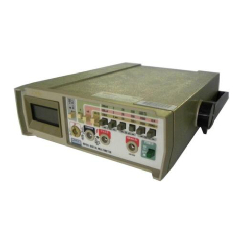
Fluke 8050? User manual

P/N
530907
October
1979
R
ev 2
7/84
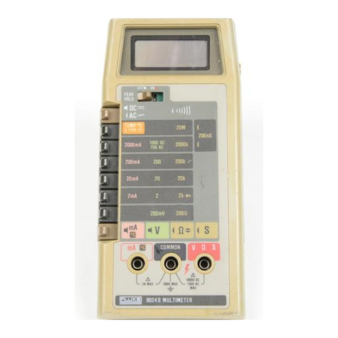
8050
Α
Digital
M
ultimeter
Instruction
Manual
FLU
ΚΕ

N
otwit
h
sta
nd
i
n
g
any
provision
o
f
any ag
r
ee
m
ent
t
he
followi
n
g
wa
rr
a
n
ty
is
excl
u
sive
:
Th
eJ
O
HN
FLUKE
MF
G
.
CO
.,
I
NC
.,
wa
rr
an
ts
each
instrument
it
m
a
nu
fact
ur es
to
b
e
f r
ee
f r
om
d
efects
i
n
mate
r
ial
a
nd
wo
rkm
a
n
s
h
i
p
und
e
r
no
rm
al
u
se
a
nd
se
r
vice
for
t
he
p
e
r
io
d o
f
1-yea
r
f
r
o
m
d
ate
of
purc
h
ase
.
T
h
iswa
rr
an
ty
exte
ndso
nly
to
t
heo
r
igi
n
al
purc
h
ase
r
.
Th
is
wa
rr
an
ty s h
all
not
apply
to
f
u
ses,
d
is
p
osa
b
le
b
atte
r
ies
(
r
ech
a
r
gea
b le ty p
e b
atteries
a
r
e
wa
rr
an
te
d
f
o
r
90-d
ays),
o
r
any
pr
odu
ct
o
r p
a
rts
w
h
ic
h have b
ee
ns
ubj
ect
to
m
is
u
se,
n
eglect,
acci
d
e
n
t,
o
r
abno
r
mal
co
nd
itio
ns o
f
ope
r
atio
n
s
.
In
t
he even
t
o
f
fail
ur
e
of
α
pr
o
du
ct
cove
r
ed by
t
h
is
wa
rr
a
n
ty,
J
o
hn
F
l
uk
e
M
fg
.
Co
.,
I
n
c
.,
will
re
p air
and
cali
br
ate
an
i
n st
rum
e
n
t
r
et
urned
to
an
a
u
t
ho
r
ize
d
Se
r
vice
F
acility
wit
h
i
n
1
yea
r
of
t
he o
r
igi
n al
purchase
;
p
rovi
ded
t
h
e
wa
rr
an
tor's
exami
n
atio
n d
iscloses
to
its
satisfactio
n
th
at
t
he p
ro
du
ct
was
d
efective
.
T
h
e
wa
rr
an
to
r
m
ay,
at
its
op
tion,
r
ep
lace
t
he
pr
o
du
ct
i
n
lieu
of
re
p
ai
r
.
W
it
h
r
ega
rd
to
any
i
n st
rum
e
n
tr
et
urn
e
d
wit
h
i
n
1
yea
r
of
t
heo
r
igi
n
al
purch
ase,
sai
d
r
e
p
ai
r
s
or
r
ep
lace
m
e
n
t
will
be
m
a
de
wit
h
ou
t
ch
a
r
ge
.
If
t
he
fail
ur
e
h
as bee
n
ca
u
sed by
m
is
u
se,
n
eglect,
acci
den
t,
o
r
a
bn
o
rm
al
co
nd
itio
n
s
of
ope
r
atio
n
s,
r
ep
ai
r
s will
be b
ille
d
at
α
n
o
m
i
n
al
cost
.
In s
uch
case,
an
esti
m
ate
will
b
e s
ubm
itte
d b
efore
wo
rk
is
sta
r
te
d
,
if
re
qu
este
d
.
ΤΗΕ
F
O
RE
GOIN
G
WA
RRANTY
IS IN
L
I
EU
O
F
A
LL
OT
HER
W
A
RR
AN
TI
E
S,
EX
PRE
SS
O
R
I
MPL
I
E
D,
I
NCLU
DI
N
G
BU
T
NOT
L
I
M
IT
E
D
TO
ANY
I
MPL
I
ED
W
A
R
RA
N
TY
O
F
MER
CHA
N
TA
B
I
L
ITY,
F
IT
NE
SS,
O
R
AD
E
QU
ACY
F
O
R
ANY
PAR
TIC
ULA
R
PURP
OS
E
O
R
U
S
E
.
J
O
HN
FLUKE
MF
G
.
CO
.,
I
NC
.,
S
HA
LL
NOT
BE
LIA
BLE
F
O
R
ANY
S
PE
CIA
L
, I
N
CID
ENTA
L
,
O
R
CO
NS
E
Q
UEN
TIA
L
DA
M
AG
ES
.
WHE
THER
IN
CON
TR
ACT,
TORT,
OR
OT
HERW
IS
E
.
If
any
f
ail
ure
occurs,
t
he
followi
ng
ste
p
ss
hou
l
d be
ta
k
e
n
:
WA
RR
A
N
TY
1
.
N
otify
t
h
e
J
O
HN
FLUKE
MF
G
.
CO
.,
I
NC
.,
or
n
ea
r
est
Se
r
vice
facility,
givi
ng
f
u
ll
d
etails
of
t
h
e
d
iffic
u
lty,
a
nd
i
n
cl
ud
e
t
he
m
od
el
numb
e
r,
type
numb
e
r,
a
nd se
r
ial
numb
er
.
On
recei
p
t
of
t
h
is
i
n
fo
rm
atio
n
,
service
d
ata,
or
sh
i
pp
i
n
g
i
n
str
u
ctio
n
s
will
b
e
forwa
rd
e
d
to
you
.
2
.
On
r
ecei
p
t
of
t
h
e s
h
i
pp
i
ng
i
n
st
ru
ctio
n
s,
forward
t
h
e
inst
ru
me
n
t,
t
r
a
n
spo
r
tatio
n p
re
p
ai
d
.
R
ep
ai
r
s will
b
e
m
ade
at
t
he
Service
F
acility a
nd
t
h
e
i
n
str
um
en
t
ret
urne
d,
t r
a
n
spo
r
tatio
n p
re
p
ai
d
.
S
H
I
PP
I
NGTOM
A
NUFACT
URER
F
O
RREP
AI
R
O
R
AD
JUST
MEN
T
All s h
i
pm
en
ts
of
J
O
HN
FLUKE
MF
G
.
CO
.,
I
NC
.,
i
n
str
um
e
n ts s
h
o
u
l
d be
m
ade
via
U
nite
d
P
a r
cel
Service
or
"Best
W
ay"'
pr
ep
ai
d
.
The
i
n
str
um
ent
s
hou
l
d
b
e
s
h
i
pped
i
n
t
he
origi
n al
pack
ing
carto
n
;
or
if
it
is
not
availa
b
le,
use any
s u
ita
b
le
con
tai n
e
r
t
h
at
is
r
igi
d
a
nd
of
a
de
qu
ate
size
.
If
α
s
ub
stit
u
te
co
n
tai
n
e
r
is
u
sed
,
t
he
i
n
st
rum
e
n
t
shou
l
dbe
wra
pped
i
n
pap
er
a
nd
s
urr
o
und
ed
wit
h
at
least
fo
ur
inc
hes
of
excelsior
o
r
simila
rs
hock
-a
b
sorbi
ng
m
ate
r
ial
.
C
LAI
M
F
O
R
DA
MAG
E
IN
SH
I
PMEN
T
TO
O
R
IGI
NA
L
PUR
CH
AS
ER
T
he
i
n
str
um
en
t
s
ho
u ld
be
t
h
orough
ly
i
n
sp
ecte
d im
m
ed
iately
upon
o
r
igi
n al
d
elivery
to
pu
rc
hase
r
.
All
m
aterial
i
n
the
con
tai
n
e
r s
h
o
u
l
d
bech
ec
ke
d
agai
n
st
t
he en
close
dpack
i
ng
list
.
T
he
m
a
nu
fact
u
rer will
n
ot
be
r
espo
n
si
b
le
for s
h
ortages
agai
n
st t
he pac
k
i
ng
s
h
eet
un
less
n
otifie
d
i
mm
ed
iately
.
If t
he
i
n
str
um
e
n t is d
amage
d
i
n
anyway,
α
clai
m
s h
ou
l
d be
file
d
wit
h
t
he ca
rr
ie
r
i
m
med
iately
.
(To ob
tai
nαqu
otatio
n
to r
e
pair
sh
i
pm
e
n
t
da
m
age,
con
tact
t
h
e
n
earest
F
l
uk
e
Tec
h
nical
Ce
n
ter
.)
F
i
n
al clai
m
a
nd
n
egotiatio
n
s
wit
h
t
he ca
rr ie
r
m
u
st
be
co
mp
lete
d
b
y
t
he
c
u
sto
m
e
r
.
T
he
J
OHN
FLUKE
MF
G
.
CO
.,
I
N
C,
will b
eha
pp
y
to
a
n
swe
r
all
a
pp
licatio
n
s o
r
use
qu
estio
n
s,
w
h
ic
h
will
enh
a
nce yo
ur
use
of
t
h
is
i
n
st
rum
en
t
.
P
lease
add
r
ess
yo
ur
r
e
qu
ests
o
r
co
r
res
p
o
nd
ence
to
:
J
O
HN
FLUKE
MF
G
.
CO
.,
I
N
C
.,
Ρ
.
Ο
.
BOX
C9090,
EVERE
TT,
W
ASH
I
N
GTO
N
98206,
ΑΤΤΝ
:
Sales
De
p
t
.
Fo
r
Eur
o
pean
C
u
sto
m
e
r
s
:
F
l
uke
(
H
olla
nd
)
B
.V
.,
Ρ
.
Ο
.
Box
5053,
5004
ΕΒ
,
Tilb
ur
g,
T
he
N
ethe
r
la
nd
s
.
'
F
or
European
custo
m
e
rs,
Air
Fr
eig
h
t
pr
ep
ai
d
.
J
ohn
F
l
uk
e
M
fg
.
Co
.,
Inc
.,
Ρ
.
Ο
.
Box
C9090,
E
verett,
W
as
h
i
ngton
98206
R
ev
.
6/81

3
Table
of
Co
n
tents
SE
CTIO
N
TIT
LE
P
AG
E
1
I
NT
R
OD
U
CTIO
NAND
SPE
CI
F
ICATIO
N
S
.
.
.....
....
......
. .
.....
. .
. .
1-1
1-1
.
IN
T
RO
DU
CT
I
O
N
. .
........
....
...
.
.....
.
.
.
.......
. .
....
...
. .
1-1
14
.
O
P
T
I
ON
S
A
ND
ACC
E
SSO
R
IE
S
. .
. .
.
.....
....
......
. .
....
...
. .
1-1
1-5
.
S
PE
C
IFI
CA
TI
ON
S
. .
....
....................
.
.
.
.
.
...........
.
1-1
2
O
PER
ATIO
N
......
.
.....
.
.........
.
...
....
....
.
.. .
..
.... .
.
....
.
. .
.
.
2-1
2-1
.
IN
TR
O
DU
C
TI
ON
.
.......
.
.
. .
....................
. .
....
...
...
2-1
2-3
.
SE
TT
IN
G
UPYO
UR
IN
S
TRUMEN
T
..............
. .
....
...
...
2-1
2-4
.
Unp
ac
k
i
n
g
....
. .
....
.
...
...
.....................
.
.....
. .
...
2-1
2-8
.
AC
Lin
e
V
o
l
tage
R
e
qui
re
m
e
n
ts
..............................
.
2-1
2-10
.
Fu
se
R
e
p
lace
m
e
n
t
...
. .
.........................
.
...........
.
2-1
2-13
.
FRONT
P
A
NEL
FE
A
T
U
RE
S
.................
.
................
.
2-2
2-15
.
Di
s
pl
a
y
..........
.
.............
.
.
.
. .
. .
....
. .
......
.
.......
.
2-2
2-18
.
S
I
G
N
A
L
INPU
T
LIMIT
S
.........
.
. . . .
. .
....
...
.....
.
......
.
.
2-2
2-20
.
O
PER
A
TIN
G
T
E
C
HNI
Q
UE
S
.....
....
...
. .
.
.
.
...
..............
2-3
2-22
.
AC/
D
C
Voltage
(V)
......
. .
. .
.
...................
.
....
.
.
.
...
2-3
2-24
.
AC/
D
C
Current
(
m
A)
. .
.
.
. .
.....................
. .
....
. .
....
Ζ-3
2-26
.
Resistance
(fl)
...
...
.
...
.
.
.
.....................
..
....
.
.....
2-7
2-28
.
Co
n
d
u
cta
n
ce(S
=
1
Ω
)
..........................
.
.....
.
......
2-7
2-30
.
Di
ode
T
est
.
.
......
. .
................
.
........
.
......
.
.....
.
2-7
2-32
.
R
e
l
at
iv
e(REL
A
TI
V
E)
................
.
........
.
......
.
.....
.
2-7
2-36
.
Decibel
(dB)
...................
.
.
. .
.
.
.
.
. .
.
. .
..............
.
.
2-11
2-38
.
INITI
A
LC
HECKOUT
PR
OC
EDURE
. .
...
.
.
.
. .
.
.
............
. .
2-12
2-41
.
A
PPLI
CA
TI
ON
S
. . .............
. .
. . . .
.
.....
. .
..............
.
.
2-12
2-43
.
D
C
V
o
l
tage
M
eas
u
re
m
e
n
t
...
.....................
. .
.....
.
....
2-12
2-51
.
Current
M
eas
u
re
m
e
n
t
. .
....
.....................
. .
..........
2-13
2-56
.
R
es
i
sta
n
ce
M
eas
u
reme
n
t
.
...
....................
. .
....
.
......
2-13
2-62
.
Co
n
d
u
cta
n
ce
M
eas
u
re
m
en
t
.....................
. .
.....
.
......
2-14
2-80
.
R
elat
i
ve
M
eas
u
re
m
e
n
t
..........................
.
....
. .
......
2-16
2-84
.
AC
V
o
l
tage
and
Current
M
eas
u
reme
n
t........... .
.
.....
.
......
2-16
T
HE
O
RY
O
F
O
PER
ATIO
N
.............
.
. . . .
...
. . . .
.
. .
.
.....
.
........
3-1
3-1
.
INTR
O
DU
C
TI
O
N
.............
. .
..
.
.
.
.... .
..
.
..............
.
.
3-1
3-3
.
FUNC
TI
ONA
L
DE
SC
RIPTI
O
N
. .
. .
.
.
.
.....
. .
.
......
.
.......
.
.
3-1
3-5
.
C
IR
C
UIT
DESCRIPTION
.
.
.
.
......................
.
.......
.
. .
3
.1
i
(co
n
t
inu
edonpage
ii)
L
ist
of
F
igures
FIG
URE
TIT
LE
P
AG
E
F
ro
n
tis
p
iece
8050
Α
Dig
i
ta
l
Mul
t
im
eter
.
. .
.
.
......
. .
. .
.
...........
.
. .
.
.
.
. .
.
.
..
... .
v
i
1-1
.
8050A
Dimensions
. .
.
....
.
.......
....
. .
.
..........
...
.
.
.....
...
...
.
1-6
2-1
.
Co
n
trols,
In
dicators,
a
n
d
Co
nn
ectors
...
....
..............
. .
....
. .
....
2-2
2-2
.
Liqui
d
Crysta
l
Di
s
pl
a
y
. .
. .
......
....
........
...
.
.
.
....
.....
.
......
. .
2-4
2-3
.
AC/
D
C
V
o
l
tage
O
p
e
r
atio
n
......
....
........
..........
.....
.
......
. .
2-5
2-4
.
AC/
D
C C
u
rre
n
t
O
p
erat
i
o
n
......
....
........
......
.
...
.....
. .
.....
. .
2-6
2-5
.
R
es
i
sta n ce
O
p
erat
i
o
n
.
...
...
...
.........
.
.
. .
.............
. .
.....
. .
. .
2-7
2-6
.
Co
n
d
u
cta
n
ce
O
p
erat
i
o
n
. .
....
. .
.........
.
. .
.
.
.
...........
.
.......
.
. .
2-8
2-7
.
Di
ode
Test
O
p
erat
i
o
n
....
.
.
.
......... .
...
.........
.
...
...
...
...
....
2-9
2-8
.
R
e
l
at
iv
e
Operat
i
o
n
.'
. .
....
...
.......
. .
.
.
..............
....
...
...
....
2-10
2-9
.
d
B
V
o
l
tage
O
p
erat
i
o
n
....
. .
........
. .
.
. .
..............
. .
.....
. .
....
2-11
2-10
.
C
i
rc
ui
t
Loading
E
rror
..........
....
.........
.
. .
.
.
....
.....
.
.
.
....
. .
2-13
2-11
.
Ca
l
c
ul
at
in
g
Bu
rde
n
V
o
l
tage
E
rror
...
..........
....
.
. .
.......
.
......
. .
2-14
2-12
.
T
ra
n
s
i
stor
B
eta
T
est
Fi
xt ure
......
...
.........
.
. .
.
.
. .
.
.
.......
.
.....
.
2-15
2-13
.
d
B
C
i
rc ui
t
Ga
in
or
L
oss
M
eas
u
re
m
e
n
ts
. .
.
. .
.
.
.
.....................
.
.
2-17
2-14
.
W
ave
f
or
m
Co
mp
ar
i
so
n
s
......
.
...........
...
.............
.
.....
...
.
2-18
2-15
.
Crest
F
actor
. .
..
...
...
....
. .
.........
.
.
. .
.
.
............
.
......
.
...
2-19
2-16
.
Total
RM
S
V
a
lu
e
. .
.
.
.
....
. .
.......
.
.
.
................
. .
....
.
......
2-19
2-17
.
M
eas
ur
in
g
A
m
plif
i
er
B
a
n
dw
i
dt
h
......
....
..............
...
...
.
.
.
....
2-20
3-1
.
8050
Α
Fun
ct
i
o
na
l
Bl
ock
Di
agra
m
.....
....
........
.
......
. .
... .
.
.
.
....
3-3
3-2
. -
Α
/
D
Co
n
verter
...
.
.....
. .
.....
..
.
.
............
.. .
. .
...
....
...
.....
3-4
3-3
.
Α
/
D
Co
nv
erter
W
ave
f
or
m
s
.....
. .
.
.
.............
. .
. . .
. .
....
. .
......
3-5
3-4
.
Mi
croco
mpu
ter
S
implif ied Bl
oc
k
Di
agra
m
....
.
.
.
.
.....
. .
.
. . . .
.
.....
. .
3-6
3-5
.
S
i
g
n
a
l
Co
n
d
i
t
i
o
nin
g
. .
...
....
. .
.
.
..........
....
. .
. .
.......
.
.
.
....
. .
.
3-7
3-6
.
RM
S
Co
n
verter
.....
. .
...
.
.
. .
............
..
.... .
.
.......
.
......
. .
.
3-9
4-1
.
Di
zi
μ
l
ay
P
C
B
Access
.
. .
....
.
.
.
........
.
. .
.
.
. .
.............
.
.... .
...
.
43
4-2
.
Ca
li
brat
i
o
n
Ad
j
u
st
m
e
n
t
L
ocat
i
o
n
s
....
....
...............
...
....
. .
....
49

8050
Α
Digital
Mu
itimete
r
v
i

1-1
. I
N
T
R
OD
U
CTIO
N
1-2
.
Your
J
ohn
Fluk
e
Model8050A
i
s
α
portab
l
ebenc
h
-
type
d
i
g
i
ta
l
mul
t
im
eter
(DMM)
w
i
t
h
α
4-1/2
d
i
g
i
t
liqui
d
crysta
l
d
i
sp
l
a
y
(L
C
D)
.
T
he
8050
Α
h
as
all
t
he
f
o
ll
ow
in
g
in
du
stry-sta
n
dard
f
eat
u
res
:
ι
V
o
l
tage
m
easu
re
m
e
n
ts
f
ro
m
10
μ
V
to
Ι
OOO
V
do
an
d
10
m
V
to
750
V
tr
u
e-r
m
s
ac
.
ι
C
u
rre
n
t
m
eas
u
re
m
e
n
ts
f
ro
m
10
ηΑ
to
2
Α
do an
d
10
μΑ
to
2
Α
tr
u
e-r
m
s
ac
.
ι
R
es
i
sta
n
ce
m
easu
re
m
e
n
ts
f
ro
m
ΙΟ
mil
to
ΖΟΜΩ
.
Th
e
8050
Α
also
h
as
se
v
era
l
s
pec
i
a
l
m
easu
re
m
en
t
f
eat
u
res
.
Th
ese
s
pec
i
a
l
f
eat
u
res
i
n
c
lu
de
t
h
e
following-
0
Co
n
d
u
cta
n
ce
m
easu
re
m
en
ts
up
to
100,000
ΜΩ
.
ι
V
o
l
tage
m
eas
u
re
m
en
ts
i
ndec
i
bels,
t
h
at
can
be
re
f
ere
n
ced
to
1
of
16
u
ser
se
l
ected
re
f
erence
imp
eda
n
ces
.
ι
R
es
i
sta
nce
ra
n
ges
t
h
at
s
uppl
ye
n
o
u
g
h
vo
l
tage to
t
u
r
n
on
α
ΡΝ
j
un
ct
i
o
n
to
allow
d
i
odes
a
n
d
tra
ns
i
stors
to
be
tested
.
T
he
ab
i
lity
to
store
an
y
inpu
t s
i
g
n
a
l
as
an
o
ff
set
or
relat
i
ve
re
f
ere
n
ce
va
lu
e
.
Sectio
n
1
Introduction
an
d
Specificatio
ns
ι
A
uto
m
at
i
c
p
o
l
ar
i
ty
in
d
i
cat
i
o
n
a
n
d
overra
n
ge
i
n
d
i
cat
i
o
n
.
ι
P
rotect
i
on
f
ro
m
ove
r
l
oads
a
n
d p
rotect
i
on
f
ro
m
trans
i
en
ts
o
f
up
to
6k
V,
10
mi
croseconds
.
ι
Dual-slope
in
tegrat
i
on
α
/d co
n
vers
i
o
n
to
en
sure
no
i
se-
f
ree
m
easu
re
m
en
ts
.
L
on
g
ter
m
ca
li
brat
i
o
n
stab
i
lity
(1
year)
.
1-3
.
T
h
e
8050
Α
i
s
warra
n
ted
f
or α
p
er
i
od
o
f
one year
upon
s
hipm
e
n
t
o
f t
he
in
str
um
en
t
to
t
he or
i
gi
n
a
l
pu
rchaser
.
Co
n
d
i
t
i
o
ns o
f
t
he
warra
n
ty
are
g
i
ven
at
t
he
f
ron
t
o
f
t
hi
s
m
a
nu
a
l .
Th
e
8050
Α
is
t
ypi
ca
ll
yp
owered
f
ro
m
ac
lin
e
vo
l
tages
b
u
t
m
ay be p
owe
r
ed
b
y
t
he
o
p
t
i
o
n
a
l
rec
h
argeab
l
e
battery
.
1-4
.
O
P
TIO
N
S
a
nd
ACC
E
SSO
R
I
E
S
1-5
.
T
h
e
u
se
o
f
t
h
e
8050
Α
can
be
enh
a
nced
b
y
t
he
accessories
avai
l
ab
l
e
f
or
t
hi
s
in
str
um
en
t
.
Th
e
accessories
are
li
sted
in
T
ab
l
e
Ι
-1
.
T
hi
s
in
st
r
um
en
t
canbe orde
r
ed
w
i
t
h
t
h
e
O
p
t
i
o
n
805
ΟΑ
-01
R
ec
h
argeab
l
e
B
attery
.
D
eta
il
ed
inf
or
m
at
i
on
on
opt
i
o
n
s an
d
accessor
i
es
i
s
con
ta
in
ed
in
Sect
i
o
n
6
o
f
t
hi
s
m
anu
a
l
.
1-6
.
S
PE
CI
F
ICATIO
N
S
1-7
.
S
p
ecificat
i
ons
f
or
t
he
8050
Α
are
li
sted
in
T
ab
l
e
1-2
.
Specifications
f
or
t
he
O
p
t
i
o
n
8050
Α
-01
R
ec
h
argeab
l
e
B
attery
an
d
oth
er
accessory
s
p
ecificat
i
o
ns are
g
iv
en
in
Sect
i
o
n6
o
f
t
hi
s
m
a
nua
l .

I
NTR
OD
U
CTIO
N
S
PE
CI
FICATIO
NS
ELE
CT
R
ICA
L
. . . .
.
.
. .
.
.
. .
.
. .
.
.
.
. .
.
. .
.
. .
.
.
. .
The
elect
r
ical
sp
ecificatio
ns
give
n apply
fo
r
an op
e
r
ati
ng
tem-
perature
of
18°C
to
28°C
(64
.4°
Fto 82
.4°
F),
r
elative
hum
i
d
ity
up
to
90%,
an
dα
1-year
cali
b
ration
cycle
.
Fun
ctio
ns
.
. .
.
.
. .
.
.
.
. .
.
. .
.
. .
.
.
.
. .
. .
.
. .
.
.
.
.
DC
volts,
AC
volts
(li
n
ea
r
a
nd
dB),
DC
c
ur
re
n
t,
AC
c
urr
e
n
t,
r
esista
n
ce,
d
io
de
test,
co
ndu
cta
n
ce,
r
elative
.
DC
V
oltage
Ta
b
le
1-1
.
8050A
Accessories
Ta
b
le
1-2
.
8050
ΑS
p
ecificatio
ns
I
NPU
T
I
MPE
DA
N
C
E
.
.
. .
. . . .
.
. .
.
...
.
.
.
.
.
10
ΜΩ
i
n
p
arallel
wit
h
<100
pF,
all
ra
n
ges
.
N
O
RM
A
L
M
OD
E
REJE
CTIO
N
R
ATIO
.
.
.
>60
dB
at
60
Hz
or 50
Hz
.
CO
MM
O
N
M
OD
E
REJE
CTIO
N
R
ATIO
. .
.
>90
dB
at
d
c,
50 Hz
or 60
Hz
(1
k
Ω
unb
ala
n
ced)
(>120
dB
availa
b
le
on
r
e
qu
est)
CO
MM
ONM
OD
E
V
O
L
TAG
E
(M
AXI
MUM)
500
Vdoo
r
p
ea
k ac
RE
SP
O
N
SE
TIME
TO
...
.
. .
.
.
.
. .
.
. .
.
.
.
.
.
1
seco
nd
maxim
u
m
RAT
E
D
ACC
UR
ACY
M
AXI
MUM
I
NPU
T
.
.
.
. .
.
. .
.
.
.
. .
.
. .
.
. . .
.
.
1000
V
d
o or
p
eak
acco
n
ti
nu
o
us
(less
t
ha
n10
seco
nd
s
du
ratio
n
on
both
t
h
e
200
mV
a
n
d 2
V
r
an
ges)
.
'DC
voltages
can
also
be
meas
u
re
du
si
n
g
t
h
e
d
B
mo
de
wit
h
.01
dB
r
esol
u
tio
n
b
etwee
n
5%
of
r
an
ge
and
f
u
ll
range
.
M
OD
EL
D
E
SC
R
I
P
TIO
N
M
OD
EL
D
E
SC
R
I
P
TIO
N
C86
Ru
gge
d
ize
d
Ca
r
rying
Case
80J-10
C
u
rr
en
t
S
hun
t
Υ
8205
Soft
Ca
r
ryi
ng
Case
80
Κ
-6
H
ig
h
V
oltage
Pro
be
MOO-200-611
Offset
M
o
un
ti
n
g
Kit
80
Κ
-40
H
ig
hV
oltage
Pro
be
MOO-200-612
Cente
r
M
ou
nti
ng
Kit
83-
RF RF
Pro
b
e
MOO-200-613
D
u
al
M
o
un
ti
ng
Kit
85-
RF RF
Pr
ob
e
80T-
Η
To
uch
-
H
ol
d Pr
o
be
Y81
00
DC/AC
C
urr
en
t
Pr
o
be
80T-150C Te
mp
e
r
at
ur
ePro
b
e,
Celsi
u
s
Y81
01
AC
C
ur
re
n
t
T
r
an
sfo
r
mer
807-150
F
Tem
p
e
r
at
ur
e
Pr
o
b
e,
Fa
h
re
nh
eit
Υ
8134
Del
u
xe Test
Lea
dSet
(safety
d
esig
n
e
d
)
80
Ι
-600
Cu
rr
en
t
Tran
sfo
rm
e
r
Υ
8140
Sli
m
-
F
lex
Test
L
eads
R
A
NG
E
RE
SO
LU
TIO
N
ACC
UR
ACY
fo
r
1-Yea
r
±200
m
V
10
μV
±2
V
100
μ
V
±20
V
1
mV
±(0.03%
of
rea
d
i
n
g
+2
d
igits)
.
±200
V
10
mV
±1000
V
100
mV

Ta
b
le
1-2
.
8050
Α
Specificatio
ns
(
οοπ
t)
I
N
TR
ODU
CTIO
N
SPECIF
ICATIO
N
S
AC
V
olts
(Tr
u
e
RM
S
R
espond
i
n
g,
AC
Co
up
le
d
)
V
O
L
TAG
E
RE
ADO
UT
ACC
UR
ACY
.
.
.
...
t(%
of
r
ea
d
i
ng
+
numb
e
r
of
d
igits),
b
etwee
n
5%
of
r
an
ge
a
nd
f
u
ll
r
an
ge
.
"'
Τy
ρίεα
//y
3
to
5
digits
of
r
attle
will
b
eob
serve
d
at
f
u
ll
scale
at
20
Hz
.
RE
SO
LU
TIO
N
.
. .
.
.
. .
.
.
.
.
. .
. .
.
..
.
.
. .
. .
.
.
0
.01
dB
fro
m
5%
of
scale
to
f
u
ll
scale
;
0
.1
dB
fr
o
m
1-5%
of
scale,
1
dB
below
1%
of
scale
V
O
L
T
-
HzPR
OD
U
CT
10'
m
ax (200
V
max
@
50
kH
z)
EXT
EN
D
E
D
dB
S
EN
SITI
V
ITY
.
.
. .
.
. .
.
.
. .
Ty
p
ically
-72
dB
(600
Π
R
ef)
±1 dB
to
10
kH
z
E
XT
EN
DED
FRE
Q
UEN
CY
RE
SP
O
N
SE
. .
Ty
p
ically
-3
d
El
at
200
kH
z
CO
MM
O
N
M
OD
E
REJE
CTIO
N
. .
. .
.
. .
.
. .
>60
dB
at
50
Hz
or
60 Hz
R
ATIO
(1
k
Ω
unb
ala
n
ce)
C
RE
ST
F
ACTO
RR
A
N
G
E
. .
. .
.
...
.
.
. .
.
.
.
W
avefo
r
ms
wit
h
α
P
eak/
RM
S
r
atio
of
1
:1
to
3
:1
at
f
u
ll
scale,
i
n
c
r
easing
d
ow
n
ra
n
ge
I
NPU
T
I
MPE
DA
N
C
E
. .
. .
.
.
. .
.
.
. .
. .
.
.. ...
10
ΜΩ
i
npa
r
allel
wit
h
<100
pF
M
AXI
MUM
I
NPU
T
V
O
L
TAG
E
. .
.
..
.
. .
.
..
750
V
rm
s or
1o00
V
p
eak
co
n
ti
nu
ou
s
(less
t
h
a
n
10
seco
nd
s
dur
atio
n
on
b
ot
h
t
h
e
200
mV
a
nd
2
V
r
a
n
ges),
n
ot
to
excee
d
t
he
volt-
h
ertz
pro
du
ct
of 10'
RE
S
P
O
N
SE
TIME
. .
.
.
.
. .
.
. . . .
. .
.
.
. .
.
. .
.
2
seco
nd
s
maxi
mum
wit
h
i
n
α
r
an
ge
REFEREN
CE
IMPE
DA
NC
ES
.
.
.
. .
.
. .
.
. .
.
Sixtee
nu
ser-selecta
b
le
i
mp
eda
nce
r
efere
n
ce
levels
a
r
e
p
rovi
d
e
d
to
r
efe
r
en
ce
α0d
Bm,
1
mW
level
(50
Ω
,
75
Π
,
930,
110171,
1250, 1350,
1500,
2500,3000,5000,
6000,
8000,9000,10000,12000),an
d
an
80
i
mp
eda
n
ce
r
efere
n
ce
level
is
pr
ovi
de
d
to
r
efe
r
e
n
ce
α
0
dBW
level
.
dB
Ranges
NOTE
.
On
req
u
est,
t
h
e
NOT
S
PE
C
IFIED
portion
of
t
h
e
100
Υ
-750V
Ra
nge can
be
exten
d
e
d
to
t
h
e Vo
l
t-
H
ertz
Product
of
10?
INPU
T
Ι
dBm
VO
L
TAG
E
(600
Ω
REF)
0
.77
mV
-2
mV
2
mV
-2
V
0
.1
V
-2
V
1
V
-20
V
10
V
-
200
V
100
V
-
750
V
-60
το
-52
-52
to
+8
-18
to
+8
+2
το
+28
+22
το
+48
+42
το
+60
R
A
NG
E
20
Hz
45
Hz
1
kH
z
10
kH
z
20
kH
z
50kH
z
ACC
UR
ACY
:
fro
m
596
of
r
an
ge to
f
u
ll
scale,
1-year
When
200
m
V
ra
n
ge
is
selected
t
he
8050
Α
a
u
toranges fo
r
b
est
accuracy
fo
r2
V
i
npu
ts
and
less
.
I
NPU
T
VOLTAGE
RE
SO
LU
TIO
N
R
A
N
GE
20Hz** 45
Hz
1
kH
z
10
kH
z
20
kH
z
50
kH
z
10
mV
-200
m
V
1011
V
200
mV
Ι
0
.1V
-
2
V
1004V
2
Υ
1%+10
.5%+10
1%+10 5%+30
1
V
-
20
V
1
mV
20
V
ι
10
V
-
200
V
10
mV
200
V
l
100
V
-
750
V
100
mV
750
V

INTRODUCTION
SPECIFICATIONS
Table
1-2
.
8050
Α
S
pecifications
(cont)
OC
Current
O
VERLOAD
PROTECTION
(ac/dc)
.
. .
.
.
.
2A/250V
f
use
in
series
with
3A/600V
fuse
(for
h
igh
e
nergy
sources)
AC
Current
(True
RMS
R
esponding,
AC
Coupled)
""Ty
p
ί
cally
3
to
5d
igits
of
r
attle
will
b
e
observe
d
at
f
u
ll
scale
at
20
Η
z
.
C
REST
F
ACTORRANGE
.
. .
.
. .
.
.
.
. .
.
.
.
.
W
aveforms
with
αP
eak/RMS
ratio
of
1
:1
to
3
:1
at
full
scale
R
esistance
O
VERL
OAD
PR
OT
E
CTIO
N
.
.
. .
.
.
. .
.
.
.
.
.
500
V
dc/ac
rm
s
on
all
ra
n
ges
OPEN
CIRCUIT
V
OLTAGE
. .
.
.
.
. .
.
.
.
. . . .
Less than
3
.5V
on
all
ranges
RESPONSE
TIME
.
.
.
.
. . . .
.
.
.
.
. .
.
.
.
.
. .
.
.
10
seconds
maximum
on 20
ΜΩ
r
ange
;
2
seconds
m
aximum
on
all
(TO
R
ATED
ACCURACY)
other ranges
DIODE
T
EST
. .
.
.
.
. .
.
. . . . . .
.
. .
.
.
.
. .
.
.
.
.
.
T
hese
three ranges
h
ave
enough
voltage
to
turn
on
silicon
junctions
to
check
for
proper
forward-t0-back
resistance
.
The
2 k
Ω
r
ange
is
p
referred
and
it
marker) with α
ΙαΓοθ
r
d
iode
symbol
on
the
front
panelof the
instrument
.
The
three
non-diode
test
ranges
will
n
otturn
on
silicon
j
un
ctio
ns so
i
n
-ci
r
cu
it
r
esista
n
ce
m
easu
re
m
e
n
ts
can
b
e
made
with
t
hese
three
ranges
R
ANGE
RESOLUTION
ACCURACY
for
1-Year
BURDEN
VOLTAGE
200
μΑ
0
.01
μΑ
2
mA
0
.1
μΑ
20
m
A
1
μΑ
i(0
.3
ο
/
ο
of
reading
+ 2 d
igits
0.3V
max
200
mA
10
μΑ
2000
mA
100
μΑ
0
.9V
m
ax
INPUT
CURRENT
RESOLUTION
RANGE
20
Hz**
45 Hz 2
kHz
10
kHz
20
kHz
BURDEN
VOLTAGE
10
μΑ
-
200
μΑ
0
.01
μΑ
200
1A
Α
ι
Ι
100
μΑ
-2mA
0
.1
MA
2
mA
Ι
1
mA
-
20
m
A
1
MA
20
mA
2%+10 1%+10
2%+10
0
.3V
rms
m
ax
10
m
A
-
200
mA
10
μΑ
200
mA
ι
100
m
A
-
2000
mA
ι
100
μΑ
ι
2000
mA
ι ι
0
.9V
rms
m
ax
t
ι
-6,
έε
"_ .
;«
."τ
F
ULL
SCALE
VOLTAGE
ACROSS
R
ANGE
RESOLUTION
ACCURACY
for 1-Year
UNKNOWN
RESISTANCE
200
Ω
0
.01
Ω
.19V
+
2±(0
.1%
reading
digits
+
.02n)
2
k
Ω
0
.1n
1
.2V
20
k
Ω
1
Ω
d
igits)
.2V
±(,05%
.of
reading
+
2
200
k
Ω
1092
2V
2000
k
Ω
100n
.2V
20
ΜΩ
1
k
Ω
±(
ο
25
ωα
r
eading
+3
d
igits)
2V

Ta
b
le
1-2
.
8050
Α
S
p
eci
f
icatio
n
s (con
t)
I
NT
R
OD
U
CTIO
N
S
PE
CI
F
ICATIO
NS
Co
ndu
cta
n
ce
M
AXI
MUM
OPEN
CI
R
CU
IT
V
O
L
TAG
E
.
.
<3
.S
V
O
VERL
OAD
PR
OT
E
CTIO
N
.
. .
.
. .
.
.
. .
.
.
.
500
V
dc/ac
rm
s
on
all
r
an
ges
CO
NDU
CTA
N
C
E
UN
ITS
. .
. .
.
.
..
.
.
. .
.
. .
.
W
e
u
se
t
h
e
i
n
ter
n
atio
n
al
un
it
of
co
ndu
cta
n
ce,
t
he
sieme
n
=
S
=1/
Π
.
A
n
ot
he
r
un
it
of
co
ndu
cta
n
ce
is
t
he
m
ho
R
elative
REL
ATI
VE
REFEREN
C
E
.
..
.
.. . .
. .
.
. .
.
.
.
An
in
pu
t
app
lie
d
w
h
en
t
he
REL
ATI
VE
bu
tto
n
is
de
pr
esse
d
toth
eO
Ν
p
ositio
n
is
h
eld
as
"0"
r
efere
nce
poi
n
t
.
S
ub
se
qu
e
n
t
r
ea
d
i
ngs
i
nd
icate
t
he
d
eviation
(t) fro
m
t
h
is
p
oi
n
t
.
(
N
ote
:
REL
a
nnun
ciato
r
i
nd
icates
w
h
e
n
t
h
is
m
ode
is
e
n
a
b
le
d
)
REL
ATI
VE
ACC
UR
ACY
. .
.
.
. .
.
.
. .
.
. .
. . . .
Error
will
n
ot
excee
d
t
h
e
s
um
of
t
he e
rr
o
rs
of
t
h
e
two
meas
u
re
m
e
n
ts
ENV
I
R
O
NMEN
TA
L
Te
mp
e
r
at
ur
e
Coefficient
.
.
.
. . . .
.
...
.
.
.
.
. .
.
<0
.1 ti
m
es
t
he
ap
plica
b
le
acc
ur
acy
s
p
ecificatio
np
e
r
°C
fo
r
0°C
to
18°C
a
nd
28°C
to
50°C
(32°
F
to
64
.4°
F and 82
.4°
F
to
122°
F
)
O
p
erati
n
g
Tem
p
erat
ure
.
.
. .
.
. .
.
. .
.
.
.
. .
.
. .
.
0°C
to
50°C
(32°
F
to
122° F
)
Sto
r
age
Te
mp
e
r
at
ur
e
. .
.
. .
.
.
.
. .
.
. .
.
.
. .
.
.
. .
(wit
ho
u
t
batte
r
ies)
:
-40°C
to
+70°C
(-40°
F
to
+158°
F
)
(wit
h
batteries)
:
-40°C
to
+50°C
(-40°
F
to
+122°
F
)
R
elative
Hu
mi
d
ity
.
.
.
. .
.
.
.
. .
.
. . . .
.
.
. .
. .
.
.
.
.
Up
to
90%,
0°C
to
35°C
(32-95°
F
),
up
to
70%,
35°C
to
50°C
(95-
122°
F),
exce
p
t
on2000
k
Π
,
20
ΜΩ
,
a
nd
200
n
S
r
a
n
ges
w
here
it
is
up
to
80%,
0°C
to
35°C
(32-95°
F
)
G
ENER
A
L
M
axim
u
m
Commo
n
Mode
V
oltage
. .
.
.
. .
. . .
500
V
d
c
.
or p
ea
kac (low
terminal
pote
n
tial
wit
h
r
espect
to
powe
r
li
ne
grou
nd
Size
...
.
.
.
.
.
. .
.
.
.
.
.
. .
.
.
.
. .
.
.
.
.
.
. .
.
. .
. .
.
.
.
.
22
cm
χ6 c
m
χ
25
c
m
(8V
z
in
χ
2'
h
χ10
i
n
)
see
F
igu
r
e
1-1
W
eig
ht
.
. .
.
.
.
.
.
. .
.
.
.
. .
.
. . .
.
. .
.
. .
.
.
.
. .
.
. .
.
.
1
.08
k
g
(2
I
b
6
oz)
P
owe
r
Re
qu
i
r
e
m
e
n
ts
(
L
i
n
e
Only
M
od
els)
L
I
NE
VO
L
TAG
E
.
. .
.
.
.
.
.
. . . .
.
. .
.
. .
.
. . . .
.
90
to
110
V
ac47
to
440
Hz
105
to
132
V
ac,
47
to
440
Hz
200
to
264
V
ac,
47
to
440
Hz
Γαο
t
ο
r
γο
o
n
figu
r
ο
d
for
o
u
otQmo
r
op
coifi
οd
v
oitaga
P
O
WER
CO
N
S
UMP
TIO
N
.
.
.
.
. .
.
. .
.
.
.
. .
.
4
W
max
Sta
nd
a
rds
.
.
.
. . . .
.
.
.
. .
.
.
.
. . . .
.
.
.
. .
.
.
. .
.
.
.,
I
E
C
348
Pr
otectio
n
Class
1
RA
NG
E
RESOLU
TIO
N
ACC
UR
ACY
for
1-Yea
r
2
mS
.1
μ
S
(10
ΜΩ
)
t(0.1%
of
r
ea
d
i
ng
+
5
d
igits)
200
n
S
.01
n
S
±(0
.5°/
ο
of
r
ea
d
i
ng +20 d
igits)
(100
000
ΜΩ
)

I
N
TR
OD
U
CTIO
N
S
PE
CIF
ICATIONS
8
.55
i
n
.
(21,72
cm)-
7
.50
i
n
.
(19,05
cm)
2.52
in
.
(6,40
c
m)
10
.65
i
n
.
(27,05
cm)
-9.90
i
n
.(
Ζ
5,15
cm)
Figure
1-1
.
8050
Α
Dime
n
sio
n
s

2-1
.I
N
TR
OD
U
CTIO
N
2-2
.
Thi
s
sect
i
o
n
descr
i
bes
h
ow
to
set
up
a
n
d
m
a
ke
m
easu
re
m
e
n
ts
w
i
t
h y
our
8050
Α
.
E
ven
t
h
o
ugh
yo
u
m
ay
h
ave
u
sed
α
mul
t
im
eter
be
f
ore,
we
reco
mm
en
d
t
h
at
yo
u
read
t
he en
t
i
re sect
i
on
care
full
y
so
t
h
at
yo
u
can
u
se
all
o
f
t
he
8050
Α
f
eat
u
res
.
2-3
.
S
E
TTI
N
G
UP
YO
UR
IN
STRUMEN
T
2-4
.
Unp
ac
king
2-5
.
T
hi
s
in
stru
m
en
t is
s
hi
pped
in
α
s
pec
i
a
l
p
rotect
i
ve
co
n
ta
in
er
t
h
at
s
h
o
ul
d p
reve
n
t
da
m
age
to
t
he
8050
Α
dur
in
g
s
hippin
g
.
C
h
ec
k
t
h
e
s
hippin
g
order
aga
in
st
t
he
con
te
n
ts
o
f
t
he con
ta
in
er
an
d
re
p
ort
a
n
y
da
m
age or
s
h
ort
s
hipm
en
t
to
t
he
p
lace
o
f
pu
rc
hase or
t
he
n
earest
Fluke
Tec
hni
ca
l
Serv
i
ce
Ce
n
ter
.
Α
li
st
o
f
t
h
ese
serv
i
ce ce
n
ters
i
s
l
ocated
in
Sect
i
on5
.
T
he con
ta
in
er sh
ou
l
d
in
c
lu
de
t
he
f
o
ll
ow
in
g
.
ι
Th
e
8050
Α
M
ult
im
ete
τ
ι
Two
test
l
eads
(o
n
e red
a
n
d
πη
e
b
lac
k
)
ι
Lin
ep
ower
cord
ι
T
he
8050
Α
In
struct
i
o
n
Manual
2{
ι
.
If
res
hipm
en
t
o
f
t
h
e
in
str
um
en
t
i
s
n
ecessary,
pl
ease
u
se
t
he or
i
g
in
a
l
s
h
i
p
p
in
g
con
ta
in
er
.
If
t
heor
i
g
in
a
l
con
ta
in
er
is
n
ot
ava
il
ab
l
e,
be
su
re
t
h
at
ade
qu
ate
pr
otect
i
o
n
i
s
p
rov
i
ded
to
p
reve
n
t
da
m
age
d
ur
in
g
s
hipm
en
t .
W
e reco
mm
en
d
t
h
at
the
in
str
um
e
n
t
be
su
rro
u
ndedby
at
l
east
t
h
ree
in
ch
es
o
f
s
hock
-absorbi
ng
m
at
ε
ria
l
οη
all
οί
1c~
νΙ
L
11C
GUL
I
L
d
llICT
.
2-1
.
R
e
m
ove
t
he
8050
Α
f
ro
m
t
he co
n
ta
in
er
a
n
d
pl
ace
it
in
αcon
ven
i
e
n
t
l
ocat
i
o
n
.
To
f
ac
i
l
i
tate
o
p
erat
i
o
n
in
di
ff
ere
n
t
l
ocat
i
on
s,
t
he carry
in
gha
n
d
l
e
on
t
h
e
meter
can
Sectio
n
2
O
p
eration
be
u
sed
as
α
pro
p
-sta
n
d
or
p
os
i
t
i
o
n
ed
o
u
t
o
ft
h
e
way
.
To
p
os
i
t
i
on
t
he
ha
n
d
l
e,
pull
o
u
tward
on
t
hehubs
o
f
t
h
e
ha
nd
l
e an
d
rotate
t
h
eh
a
n
d
l
e
in
to
pos
i
t
i
o
n
.
2-8
.
AC
L
ine
V
oltage
R
e
qu
ireme
n
ts
2-9
.
AC
l
i
n
e
vo
l
tage
req
ui
re
m
e
n
ts
f
o
r
yo
u
r
8050
Α
a
r
e
li
sted
on
α
deca
l
attac
hed
to
t
he
botto
m
of
t
h
e
in
str
um
en
t
.
R
e
f
er to
Sect
i
o
n
4
f
or
t
he
proced
u
re
to
ch
a
nge
t
h
e
ac
lin
e
vo
l
tage
sett
in
g
.
CA
U
TIO
N
Do
not
co
nnect
t
h
e p
owe
r
ca
b
le
to
t
h
e
I
n
st
rum
e
n
t
b
efo
r
e
verifying
t
h
at
t
h
e
I
n
te
nded
so
ur
ce
matc
hes
t
heαε
li
ne
co
nf
ig
ur
atio
n
of
t
he
I
n
st
rum
e
n
t
.
2-10
.
Fu
se
R
eplace
m
e
n
t
2-11
.
Th
ere
is
o
n
e,
u
ser
re
pl
aceab
l
e,
fu
se
in
t
he
8050
Α
.
Th
e
fu
se,
F
1,
a
n
d
t
h
e
f
use
ho
l
der
f
or
m
an
in
tegra
l
p
art
o
f
t
he
m
A
i
npu
t
connector an
d
can
be
re
m
o
ved
w
i
t
h
o
u
t
s
p
ecia
l
too
l
s.
Th
e
f
use
rat
in
g
is
:
2
Α
,
normal
b
l
ow
(reco
mm
e
n
ded
part
AGX2)
.
2-12
.
U
se
t
he
f
o
ll
ow
in
gp
rocedu
re
to re
pl
ace
t
he
fu
se,
Σ
F1
:
1 .
Set
t
h
eP
O
W
ER
sw
i
tc
h
to
O
FF
.
2
.
R
e
m
ove
t
he
inpu
t
p
ower
cord
f
ro
m
t
h
e
8050
Α
.
W
A
RN
I
N
G
DO
NOT
ATTEMPT
TO
REP
LAC
E
ΤΗΕ
FU
S
E
W
IT
H
ΤΗΕ
I
N
ST
RUMEN
TT
URNE
D
ON
O
R
CO
NNECT
E
D
TO
L
I
NE
P
O
WER
.

OPERATION
FR
ONTPA
NEL
FE
AT
URE
S
3
.
R
efer to
F
igure
2-1,
i
tem
5
f
o
r
t
he
location
o
f
t
he
fuse
h
older
.
The
fuse
h
older
is
an
integral
p
art
of
t
he
m
A
input
connector
.
4
.
Using
α
coin
o
r
w
ide b
lade
screwdriver,
p
ush
in
whileturning
the
f
use
h
older
in
t
he
direction
of
the
arrowon
the
front
panel
decal
.
5
.
Pull
out
the
fuse
h
older
and
r
eplace
the
defective
fuse
.
2-13
.
FRONT
P
A
NEL
FE
AT
URE
S
2-14
.
B
efore
using
your
multimeter,
take
α
f
ew
m
inutes
to
become
familiar
with
t
he
u
se of
t
he
controls,
indicators,
and
connectors
of
t
he
8050
Α
.
The
f
ront
p
anel
featu
r
es are
shown
in
Figure
2-1
and
described
in
Table
2-
1
.
The
f
eatures
of
the
Liquid
Crystal
Display
(LCD)
are
also
described
in
t
he
f
ollowing
p
aragraph
.
2-15
.
Display
2-16
.
The
f
eatures
of
t
he Liquid
Crystal
Display
(LCD)
are
shown
in
detail
in
Figu
r
e 2-2
.
The
position
oft
he
floating
decimal
p
oint
i
s
determined
by
t
he
range
selected
(for linear
measurements)
.
The
m
aximum
measurement
value
that
canb
e
displayed
i
s
one
count
l
ess
than
t
he
F
ig
ur
e
2-1
.
Co
n
tr
ols, In
d
icators,
a
nd
Co
n
nectors
range
selecte
d
(e .g
.,
m
aximum
measured
voltage
that
can
be
displayed
in
t
he
200
m
V
range
wouldb
e
199
.99
m
V)
.
2-17
.
To
extend
the
l
ife
of
t
he
L
CD
a
nd
to
ensure
that
the
display
will
be
ready
to
operate,
observe
the
f
ollowing
p
recautions
:
ι
D
o
n
ot
store
or
u
se the
instrument
in
temp
eratures
above
or
below
those
specified
in
Section
1
.
ι
D
o
not
store
or
u
se the
instrument
in
humidity
above
that specified
in
Section
1
.
ΝΟΤΕ
L
ow
tem
p
eratures
(within
the
specified
operating
limits)
will
cause
the
L
CD
r
esponse
to
be
sluggish
.
ι
Avoid
prolonged
exposu
r
e
of
the L
CD
to
direct
sunlight
(ultraviolet)
.
2-18
.
SIGN
A
L
I
NPU
T
L
I
M
ITS
CA
U
TIO
N
E
xcee
d
i
ng
t
h
e
m
axI
mum
sig
n
al
I
npu
t
limits
can
da
m
age
t
he
I
n
str
u
me
n
t
.
'Nut
1015
έ
i
C
σ
Ι Ι
11
1
U
min
200
2W
1
ϋϋ
~
f
iv
ι
ι
~
ι
j
ι
f
τι
1
υΓ
"
D
.
;
. 1 .
.
ι
ι
0
:
Wu
1
,
0
MA
ίΑ
ευτε
C
F
-7
5
Fιυ
κ
ε
σσ
α
dB
i7
ωω
Μ
,ι
8050
ρ
COM
M
ON
S
1
1
Λ
Υ
/
k
Ω
/$
WW
AC
N--
.-e
!
ΦΟί
ι
Ο
t
ί
)IGITAL
M
UL
I
M
ET
ER
ΟΝ
OFF
REL
ATI
VE
ο
0

Ta
b
le
2-1
.
8050
Α
Co
n
trols,
I
nd
lcato
ι
s,
a
nd
Co
nn
ectors
O
PER
ATIO
N
O
PER
ATI
N
G
T
E
C
HN
IO
UE
S
2-19
.
B
e
f
ore
u
s
in
g
t
he
8050
Α
,
it is
imp
orta
n
t
to
n
ote
t
he
m
ax
imum
inpu
t
limi
ts
t
h
at
m
ay be
a
ppli
ed to
t
he
in
str
um
e
n
t
.
T
ab
l
e2-2
li
sts
t
he
m
ax
imum
s
i
gn
a
l
inpu
t
leve
l
s a
ll
owed
f
or
eac
h
function,
ran
ge,
a
n
d
inpu
t
connector
.
W
A
RN
I
NG
Τ
U
A
V
U
IU
ELE
GT
R
IGA
L
5
H
OG
K
,
DO
NOT
CO
NNE
CT
ΤΗΕ
CO
MM
ON
INPU
T
CO
N
-
NE
CTO
R
TO
ANY
SO
UR
CE
M
O
RE
THAN
500
V
DC,
O
R
500
V
ACRM
S
A
B
O
VE
E
A
RT
H
G
R
O
UN
D
.
2-20
.
O
PER
ATI
N
GT
E
C
HN
IQ
UE
S
2-21
.
Th
e
f
ollow
in
g
p
aragra
ph
s
describe
h
ow
to
o
p
erate
t
he
8050
Α
in
each
o
f
i
ts
seve
n prim
ary
meas
u
re
m
en
t
functions
.
R
e
f
er to
t
he
A
ppli
cat
i
o
n
s
paragraph
s
f
or
additional
m
eas
u
re
m
en
t
tec
hniqu
es
.
2-22
.
AC/DC
V
oltage
(V)
2-23
.
Fi
g
u
re
2-3 describes
h
ow
to
operate
t
he
8050
Α
f
or
ac or do
vo
l
tage
m
easu
re
m
en
ts
.
For
all
m
eas
urements,
se
l
ect
t
h
e
hi
g
h
est
ra
n
ge
t
h
at
w
ill
p
rov
i
de
t
he
re
qui
red
reso
lu
t
i
o
n
of
t
he
m
eas
u
re
m
en
t
.
If
m
easu
ri
ng
an
unkn
ow
n
vo
l
tage,
set
t
he
DMM
on
t
he
h
i
g
h
est
ran
ge,
then
(if
n
eeded)
se
l
ect
α
lower
ra
nge
.
2-24
.
AC/DC
Curro
n
t
(mA)
2-25
.
Fi
g
u
re
24
describes
h
ow
to
o
p
erate
t
he
8050
Α
for
ac
ordo
cu
rre
n
t
meas
u
reme
n
ts
.
Tu
rn
o
ff
p
ower
to
t
he
circ
ui
t
be
in
g
m
easu
red
be
f
ore brea
kin
g
t
he
c
i
rc
ui
t
a
n
d
conn
ect
in
g
t
h
e
8050
Α
in
series
w
i
t
h
t
he
curre
n
t
sou
rce
.
To
mini
m
iz
e
co
mm
o
n
m
ode
voltages,
break
t
he
circ
ui
t
on
t
he
gro
un
d
s
i
de
o
f
t
he cu
rre
n
t
source
.
Th
e
m
A
inpu
t
co
nn
ector
co
n
ta
in
s
an
i
n-lin
e
fu
se
.
If
t
he
DMM
does
n
ot
res
p
o
n
d
w
hen
m
eas
u
ri
ng cu
rre
n
t,
check
t
he
f
use
(re
f
er
to
t
he
fu
se re
pl
ace
m
en
t
p
roced
u
re
in
t
hi
s
sect
i
o
n
)
.
If
meas
u
ri
n
g
an
unknown
curre
n
t,
set
t
h
e
DMM
on
t
he
hi
g
h
est
ran
ge,
t
h
en
(i
f
needed)
se
l
ect
α
lowe
r r
a
n
ge
.
ITEM
ΝΟ
.
NAME
FUN
CTIO
N
1
Disp
lay
4
1
/2-digit
L
CD
d
is
p
lay
.
U
se
d
to
i
nd
icate
m
eas
ur
e
d
i
npu
t
values
and
an over
ι
an
geco
nd
itio
n
.
Also
co
n
tai
n
s a
nnun
ciato
ιs
fo
r
h
ig
h
voltage,
d
eci
b
el-
d
is
p
lay,
a
nd
r
elative
m
eas
ur
e
m
en
t f
un
ctions
.
2
AC/DC
Fun
ctio
n
Α
two-position
switc
h (push
IN
and
pu
sh
OU
T)
used
to select ac
:
Switc
h
(IN)
or
d
o
(O
U
T)
for
c
urr
ent
or
voltage
m
easur
eme
n
ts
.
3
V
/
m
A/
k
Π
/
d
8/S
I
n
terloc
k
ed
switc
h
es,
u
sed
wit
h
t
h
e
AC/DC
Fun
ctio
n
switc
h
to select
Fu
nctio
n
Switc
h
es
t
h
e
meas
ur
eme
n
t
f
un
ctio
n
s
.
Pu
s
h
i
n
g o
ne
switc
h
will
release
t
h
e
ot
h
ers
.
T
h
e
d
eci
b
el-
d
is
p
lay
f
un
ctio
n
is
selecte
dby
push
i
ng
t
he
V
and
m
A
switc
hes
si
mu
ltaneo
u
sly
.
T
he
co
ndu
cta
n
ce
f
un
ctio
n
is
selecte
d
by
push
ing
t
h
e
k
Λ
switc
ha
nd
on
e
of
two
p
ai
r
s
of
R
an
ge
Fun
ctio
n
switc
h
es
.
4
R
ange
Switc
h
es
I
n
te
r
loc
k
ed
switc
hes
t
h
at select
t
h
e
m
eas
ur
eme
n
t
r
an
ges
.
Pu
sh
i
n
g
α
switc
h
selects
t
he
corresponding
r
an
ge
a
nd
r
eleases
α
de
pr
esse
d
switc
h
(es)
.
5
m
A
I
npu
t
Co
nn
ector
Α
f
use p
rotecte
d
i
n
pu
t
co
nn
ector
for
c
urr
e
n
t
m
eas
ur
eme
n
ts
.
Fuse
is
accessi
b
le
f
r
om
t
h
e
fro
n
t
p
an
el
.
6
CO
MM
ON
I
npu
t
Test
lea
d
connector
u
se
d
as
t
he
1
οω
orcommon
i
npu
t
for
all
measure-
Connector
m
en
t f
un
ctio
ns
.
7
V
/
kC
V
S
I
npu
t
Test
lea
d
conn
ector
u
se
d
as
t
h
e
h
ig
h
i
npu
t
for
all
voltage,
r
esista
n
ce,
Co
nnecto
r
con
ti
nu
ity,
co
ndu
ctance a
nd
d
eci
b
el
meas
ure
m
en
t f
un
ctions
.
8
REL
ATI
VE
Fun
ctio
n
Push-on/push-off
switc
h
.
Use
d
to select
t
he
r
elative
f
un
ctio
n
for
Switch
all
meas
ur
e
m
en
ts
.
9
P
O
WER
Switc
h
Push-on/push-off
switc
h
.
U
se
d
fo
r
en
e
r
gizi
n
g a
nd
de-e
n
e
r
gizi
n
g
t
h
e
i
n
st
ru
me
n
t
.

O
PER
ATIO
N
L
CD
DIS
P
LAY
8050
Α
-01
O
NL
Y
DE
CI
BEL
FUN
CTIO
N
L
O
W
BATTERY
I
ND
ICATO
R
IN
U
S
E
P
O
L
A
R
ITY
SIGN
DISAB
LE
D
D
UR
I
N
G
V
ac,
m
AAN
D
k
Ω
FUN
CTIO
NS
8050
Α
O
VERR
ANG
E
INDICATION
8050
Α
IMPR
O
PER
SWITC
H
SE
TTI
NG
8050
Α
DIS
PL
AY
ANNUN
CIATO
RS
H
IG
HV
O
L
TAG
E
(>40
V
dc
o
r
ac
rms)
BEING
ME
AS
URE
D
REL
ATI
VE
FU
NCTIO
N
IN U
SE
ΝΟΤΕ
:
Position
of
d
eci
m
al
point
d
ep
en
d
ent
on
r
an
ge
selecte
d
.
NOTE
:
T
h
is
d
isplay
will
appea
r
if
t
he
switc
hes
of
t
h
o
ηο
6
οα
ara
set
in
an
i
m
p
ro
p
er
configuration
(e .g
.
D
C
V
20
ΜΩ
)
F
igure
2-2
L
i
qu
i
d
Crystal
Display
ι
BT dB
i
D
°
d
0 ~
σ
Q
Uσ
α
α
α
σ
Νε
L
ι

Ta
b
le
2-2
.
M
axI
mum
Inpu
t
Sig
n
al
Limits
Figure 2-3
.
AC/DC
V
oltage
Operation
O
PER
ATIO
N
AC/DC
VO
L
TAG
E
2-
5
FUN
CTIO
N
R
ANG
E
INPU
T
M
AXI
MUM
INPU
T
S
ELE
CT
E
D
S
ELE
CT
E
DT
ERM
I
N
A
L
S
O
VERL
OAD
DC
A
LL
R
A
N
G
E
S
1000
V
do
or
p
ea
k
ac
VV
/ k
Ω
/S
or
20
V
,
200
V
,
750
V
a
nd
750
V
rm
s
con
ti
nou
s
o
r
10
7
V
.
H
z
d
Β
CO
MM
O
N
AC
2
V
,
200
m
V
750
V
rm
s
fo
r
no
lo
n
ge
r
t
h
an 15
secon
d
s
o
r
10
7
V
-
H
z
DC
mA
or
A
LL
R
A
NG
E
S
mA
a
nd
CO
MM
O
N
Do
ub
le
fuse
p
rotecte
d
:
2
Α
,
250
V
f
u
se
i
n
series
wit
hα
3
Α
,
600
V
f
u
se
AC
V
/ k
Ω
/S
a
nd
k
Ω
or
S
A
LL
R
A
NG
E
S
COMMON
500
V
do
or ac
r
ms

OPERATION
AC/0C
V
O
L
TAGE
CURRENT
(mA)
1 .
SELECT
R
ANGE
2
.
SELECT
FUNCTION
3
.
CONNECT
TEST
LEADS
4
.
SREAKCIRCUIT
5
.
PLACE
8050
Α
m
S
ERIES
2-
6
Figure
2-4
.
AC/DC
C
u
r
rent
Operatlon

2-26
.
Resistance
(D)
2-27
.
F
ig
u
r
e
2-5
d
escribes
h
ow
to
operate
t
he 8050
Α
f
or
r
es
i
sta
n
ce
m
easu
r
e
m
en
ts
.
W
h
enk
Π
is
se
l
ected,
erro
n
eo
u
s
m
easu
re
m
e
n
ts
can
occ
u
r
i
f
p
ower
is
p
resent
in
t
he
r
es
i
sta
n
ce
be
in
g
m
easu
red
.
En
s
u
re
t
h
at
p
ower
is
re
m
oved
be
f
o
r e
m
easu
r
in
g
in
-c
i
rc
ui
tr
es
i
sta
n
ces
.
T
he
AC/
D
C
fun
ct
i
o
n
switc
h h
as
no
e
ff
ect
d
u
r
in
g
res
i
sta
n
ce
m
easu
r
e
m
e
n
ts
.
2-28
.
Con
du
cta
n
ce(S=1/
Ω
)
2-29
.
Fi
gu
re
2-6
descr
i
bes
h
ow
to
o
p
erate
t
h
e
8050
Α
f
o
r
con
d
u
cta
nce
m
easu
re
m
e
n
ts
.
W
h
en
S=1/fl
is
se
l
ected,
two
ra
n
ges
o
f
m
eas
u
re
m
e
n
ts
are
ava
il
ab
l
e,
2
mS
a
n
d
200
n
S
.
To
se
l
ect
either ra
n
ge,
p
ress
both
range
sw
i
tc
h
es
(above
t
he
grey-s
h
aded
area)
simu
lta
neous
l
y
.
2-30
.
Dio
de
Test
2-31
.
F
ig
u
re
2-7
descr
i
bes
h
ow
to
op
erate
t
h
e
8050
Α
f
or
d
i
ode
tests
.
T
he
t
h
ree res
i
sta
n
ce ra
nges
w
i
t
h
t
h
e
d
i
ode
sy
m
bo
l
b
es
i
de
t
h
e
ra
n
ge
va
lu
e
prov
i
de
α
m
eas
u
re
m
en
t
kvil~il
li*
I
f
ll
~~t
:3~it
τ
3
άείι
5
;ί
+
;
Σ
λθ
1~>
RE
SISTA
N
C
E
(
k
Ω
)
1
.
D
E-ENER
GIZ
E
CI
R
C
U
IT
TO
BE
ME
AS
URE
D
2
.
S
ELE
CT
R
AN
G
E
3
.
S
ELE
CT
FUN
CTIO
N
4
.
CO
NNE
CT
T
E
ST
LE
ADS
F
igu
r
e
2-5
.
R
esista
n
ce
O
p
eratio
n
2-32
.
R
elative
(REL
ATI
VE)
O
PER
ATIO
N
REL
ATI
VE
voltage
s
uffi
cient
to
ca
u
se
α
s
i
li
con
j
un
ctio
n
to
co
n
d
u
ct
.
Th
ese
r
an
ges
(2
k
Π
,
200
k
Π
an
d
20
ΜΠ
)
can
be
u
sed
to
c
h
ec
k
s
i
lico
n
dio
d
es
and
transistors
.
T
he 2
k
Π
r
es
i
sta
n
ce
r
ange
is
t
he pre
f
e r
red
d
i
ode
a
n
d
t r
an
s
i
stor
test
in
g
r
a
n
ge
a
n
d
is
labe
l
ed
w
i
t
h
t
h
e
la
r
gest
diode
sy
m
bo
l
(
)
.
F
or
α
sil
i
cond
i
ode,
t
h
e
ty
pi
cal
f
orward
b
ias
voltage
(on
t
h
e 2
k
Π
-*
ra
n
ge)
is
0
.6
V
.
Α
r
eversed
bias
s
ili
cond
i
ode
s
h
o
ul
dd
i
s
p
lay
t
h
e
overra
n
ge
i
n
d
i
cato
r
(on
t
he2k
Π
ra
n
ge)
.
2-33
.
Fi
g
u
re
2-8
descr
i
bes
h
ow
to
op
erate
t
h
e
8050
Α
f
or
re
l
at
i
ve
m
eas
u
re
m
en
ts
.
T
h
e
re
l
at
i
ve
fun
ct
i
o
n
stores
α
read
in
g
as
an
o
ff
set
or
re
l
at
i
ve
r
e
f
ere
n
ce
va
lu
e
.
W
hen
t
he
REL
AT
I
V
E
sw
i
tc
h
is
set
to
ON
du
r
in
gα
m
easu
re
m
en
t,
t
h
e va
lu
e o
f
t
h
at
m
eas
u
re
m
en
t
is
sto
r
ed,
an
d
t
he
REL
(re
l
at
i
ve
re
f
ere
n
ce)
a
nnun
c
i
ator
app
ears to
t
h
er
i
gh
t
o
f
t
he
z
eroed
dis
p
lay
.
S
ubseque
n
t
m
eas
u
re
m
en
ts
(in
t
he
sa
m
e
fun
ct
i
o
n
a
n
d
ra
n
ge)
are
d
i
sp
l
ayed
as
t
he
d
iff
erence
b
etwee
n
t
he
m
eas
ured va
lu
e an
d
t
he
sto
r
ed
re
l
at
i
ve
re
f
eren
ce
.
2-7
Table of contents
Other Fluke Multimeter manuals

Fluke
Fluke 789 Use and care manual

Fluke
Fluke 15B Use and care manual

Fluke
Fluke 707 Installation and operating instructions

Fluke
Fluke 116 User manual

Fluke
Fluke 28 II Ex Use and care manual

Fluke
Fluke 187 User manual

Fluke
Fluke 113 Use and care manual

Fluke
Fluke 233 User manual

Fluke
Fluke 87V Ex User manual

Fluke
Fluke 106 User manual