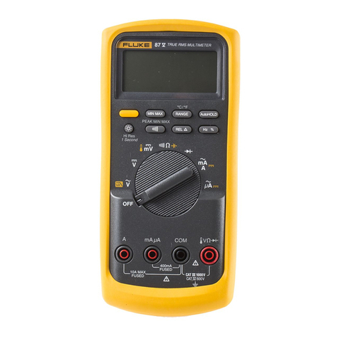
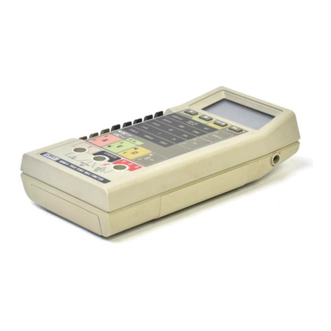
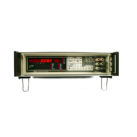
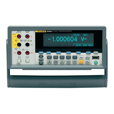
Fluke 8010A User manual

8010A/8012A
Digital
Multimeters
Instruction Manual
IFLUKEI
P/N 491944
August 1978 Rev 21/85
®1985, John Fluke Mfg. Co,, Inc. All rights reserved. Lithe in U,S.A.

8010A/8012A Digital Multimeters

Section 1
Introduction and Specifications
1-1. INTRODUCTION
1-2. This manual contains complete operating and
maintenance instructions for the Fluke Models 8010A
and 8012A Digital Multimeters. The information
presented in this manual reflects both instruments except
where indicated by aparticular model number. The term
Multimeter is used throughout this manual to indicate
both the 801 OA and the 80 12A.
1-3. The Multimeters are portable bench-type digital
niultimeters (DMMs) with 3-1/2 digit liquid crystal
displays (LCDs). The Multimeters have the following
industry-standard features:
•Voltage measurements from 100 (xV to lOOOV dc
and 10 mV to 750V true-rms ac.
•Current measurements froml00nAto2Adcandl0
/uA to 2A true-rms ac (up to lOA for the 8012A).
•Resistance measurements from 100 mO (1mO for
the 8012A) to 20 MD.
The Multimeters also have the following special
measurement features:
•Conductance measurements up to 10,000 Mfl of
equivalent resistance.
•Resistance ranges that supply enough voltage to
turn on aPN junction for testing diodes and
transistors.
•Automatic polarity indication and overrange
indication.
•Protection from overloads and transients up to 6kV
for 10 microseconds.
•Dual-slope integration a/d conversion to ensure
noise-free measurements.
•Long term calibration stability (1 year).
M. Your Multimeter is warranted for aperiod of one
year upon shipment of the instrument to the original
purchaser. Conditions of the warranty are given at the
front of this manual.
1-5. OPTIONS and ACCESSORIES
1-6. The use of your Multimeter can be enhanced by the
options and accessories available for these instruments.
The options and accessories are listed in Table 1-1. The
Multimeters can be ordered with the Option 8010A-01 or
80 12A-0 1Rechargeable Battery. Detailed information on
options and accessories is contained in Section 6of this
manual.
1-7. SPECIFICATIONS
1-8. Specifications for the Multimeters are listed in
Table 1-2. Specifications for the Option 8010A-01 or
Option 8012A-01 and other accessory specifications are
given in Section 6of this manual.
1-1

INTRODUCTION AND SPECIFICATIONS
SPECIFICATIONS Table 1-1. 8010A/8012A Options and Accessories
MODEL DESCRIPTION MODEL DESCRIPTION
C86 Ruggedized Carrying Case 80J-10 Current Shunt
Y8205 Soft Carrying Case 80K-6 High Voltage Probe
MOO-200-611 Offset Mounting Kit 80K-40 High Voltage Probe
M00-200-61
2
Center Mounting Kit 83-RF RF Probe
MOO-200-613 Dual Mounting Kit 85-RF RF Probe
80T-H Touch-Hold Probe Y8100 DC/AC Current Probe
80T-150C Temperature Probe, Celsius Y8101 AC Current Transformer
80T-150F Temperature Probe, Fahrenheit Y8133 Deluxe Test Lead Set
80i-400 AC Current Probe Y8140 Slim-Flex Test Leads
80i-600 AC Current Probe 8010A-01
8012A-01
Rechargeable Battery Option for 8010A
Rechargeable Battery Option for 801 2A
Table 1-2. 8010A/8012A Specifications
ELECTRICAL The electrical specifications given apply for an operating
temperature of 18°Cto 28''C (64.4® Fto 82.4° F), relative humidity
up to 90%. and a1-year calibration cycle.
Functions DC Volts, AC Volts, DC Current, AC Current Resistance and
Conductance.
DC Volts RANGE ^RESOLUTION ACCURACY for 1-Year
±200 mV 100 mV
±2V 1mV
±20V 10 mV ±(0.1% of reading -i- 1digit)
±200V 100 mV
ilOOOV IV
INPUT IMPEDANCE 10 MO, all ranges.
NORMAL MODE REJECTION RATIO .... >60 dB at 60 Hz (at 50 Hz with 50 Hz Option).
COMMON MODE REJECTION RATIO >90 dB at dc, 50 Hz and 60 Hz.
(1 kO unbalanced)
OVERVOLTAGE PROTECTION 1000V dc or peak ac on all ranges.
RESPONSE TIME 1second.
AC Volts (True RMS Responding)
RANGE RESOLUTION
'
ACCURACY for 1-Year (5%'of Range to Full Range)
45
to 1kHz
Hz
to 10 kHz
10 kHz
to 20 kHz
20 kHz
to 50 kHz
200 mV
2V
20V
200V
100 mV
1mV
10 mV
0.1V
+(0.5% of r£lading +2digits)
+,(1.0% of
reading +2
digits)
±(5%of
reading +3
digits)
750V IV Ji(0.5% of
reading +2
digits) ^SZI3
1-2

INTRODUCTION AND SPECIFICATIONS
SPECIFICATIONS
Table 1-2. 8010A/8012A Specifications (cont)
AC Volts, continued
VOLT-Hz PRODUCT 10^ max (200V max @50 kHz).
EXTENDED FREQUENCY RESPONSE . . .Typically ±3 dB at 200 kHz.
COMMON MODE NOISE REJECTION
RATIO (1 kQ unbalance) >60 dB at 50 Hz and 60 Hz.
CREST FACTOR RANGE 1.0 to 3.0.
INPUT IMPEDANCE 10 MQ in parallel with <100 pF.
OVERLOAD PROTECTION 750V rms or 10OOV peak continuous not to exceed the volt-hertz
product of 10^ (except 10 seconds maximum on 200 mV, 2V
ranges).
RESPONSE TIME 2seconds maximum within arange.
DC Current
RANGE RESOLLFTiON ACCURACY for 1-Year BURDEN VOLTAGE
0.1 juA
1mA
lOjLtA ±(0.3% of reading +1 digit) 0.3V max.
100 ma
1mA 0.9V max.
20 mA
200 mA'
2000 mA
OVERLOAD PROTECTION 2A/250V fuse in series with 3A/600V fuse (for high energy
sources).
AC Current (True RMS Responding AC Coupled)
RANGE RESOLUTION
200 juA 0.1 mA
2mA 1mA
20 mA IOmA
200 mA 100 /iA
2000 mA 1mA
ACCURACY: from 5% of range to full-scale, 1-Year
45 Hz 10 kHz
to 2kHz Ito 10 kHz to 20 kHz
BURDEN
VOLTAGE
±(1 %of reading
+2 digits)
2% of reading Q.3V rms max.
+2 digits)
0.9V rms max.
OVERLOAD PROTECTION 2A/250V fuse in series with 3A/600V fuse (for high energy
sources).
CREST FACTOR RANGE 1.0 to 3.0
High Current 8010A Only
RANGE RESOLUTION ACCURACY: for 1-Year BURDEN VOLTAGE
10A dc 10 mA ±(0.5% of reading +1digit) 0.5V max.
10A
Trms ac 10 mA 45 Hz to 2kHz
±(1% of reading +2digits) 0.5V rms max.
OVERLOAD 12A maximum unfused.
1-3

INTRODUCTION AND SPECIFICATIONS
SPECIFICATIONS
Table 1-2. 8010A/8012A Specifications (cont)
Resistance
RANGE RESOLUTION ACCURACY: for 1-Year FULL-SCALE
VOLTAGE MAXIMUM TEST
CURRENT
200 no.m
±(0.2% of reading
+1 digit)
<0.25V 1.3 mA
>1.0V 1.3 mA
20 kD 10D <0.25V IOmA
200 kD ^100D >uov 35 mA
2000 kn 1kn ±(0.5% of reading
+^ digit)
<0.25V 0.10 juA
20 MD -M- 10 kD >1.5V 0.35 idA
OVERLOAD PROTECTION 300V dc/ac rms on all ranges.
O'PEN CIRCUIT VOLTAGE Less than 3.5V on all ranges,
RESPONSE TIME 1second all ranges except 4seconds on the 2000 kO and 20 MO
ranges,
DIODE TEST These three ranges have enough voltage to turn on silicon
-W- junctions to check for proper forward-to-back resistance. The 2
kO range is preferred and is marked with alarger diode symbol on
the front panel of the instrument. The three non-diode test ranges
will not turn on silicon junctions so in-circuit resistance
measurements can be made with these three ranges.
Low Resistance 801 2A Only
RANGE RESOLUTION ACCURACY: for 1-Year FULL-SCALE
VOLTAGE MAXIMUM
TEST CURRENT
2D
(LO Ohms) 1mD ±(1% of reading +2
digits) 0.02V 10.5 mA
20D
(LO Ohms) 10 mD ±(0.5% of reading
+2 digits) 0.2V 10.5 mA
OVERLOAD PROTECTION 300V dc/ac rms on ail ranges.
RESPONSE TIME 1second maximum.
OPEN CIRCUIT VOLTAGE 16V maximum on both ranges.
Conductance
RANGE RESOLUTION ACCURACY; for 1-Year
OPEN
CIRCUIT
VOLTAGE
MAXIMUM
TEST
CURRENT
2mS 1mS ±(0,2% of reading
+1digit)
<3.5V 1.3 mA
20 mS 10 nS <1V IOmA
200 nS .1 nS ±(1% of reading
-t-10 digits) <1V 0.10 mA
OVERLOAD PROTECTION 300V dc/ac rms on ail ranges,
CONDUCTANCE UNITS We use the international unit of conductance, the Siemen =S=
1/D. Another unit of conductance is the mho.

INTRODUCTION AND SPECIFICATIONS
SPECIFICATIONS
Table 1-2. 8010A/8012A Specifications (cont)
ENVIRONMENTAL
Temperature Coefficient <0.1 times the applicable accuracy specification per "C for 0°C
to 18° Cand 28®C to 50“ C(32“ Fto 64.4° Fand 50.4° Fto 122° F).
Operating Temperature 0°C to 50°C (32° Fto 122°F).
RELATIVE HUMIDITY Oto 80%. 0°C to 35°C (32 to 95° F) on 2000 kO, 20 MO and 200 nS
ranges.
Oto 90%, 0°C to 35° C(32 to 95° F) on all other ranges.
0to 70%, 35° Cto 50° C(95 to 122° F)
.
Storage Temperature (without batteries): -40°C to +60°C (-40°F to +158° F)
(with batteries): -40°C to +50° C(-40°F to +122°F)
RELATIVE HUMIDITY 0to 90%, -40 to 50° C(-40 to +122° F)
0to 90%, 50 to 60° C(122 to 140° F).
GENERAL
Maximum Common Mode Voltage 500V dc or peak ac.
Power Requirements 90 to 132V or 200 to 264V at 50 Hz or 60 Hz. Line Model 2W.
(Battery Model 3.5'W.)
(See Figure 1-1.)
Weight
LINE MODEL 1.08 kg (2 lb 6oz)
BATTERY MODEL 1.42 kg (3 lb, 6oz)
-8.55 in. (21,72 cm]
-7.50 in. (19,05 cm]
10.65 in. (27,05cm)
-9.90 in. (25,15 cm).
Figure 1-1. 8010A/8012A Dimensions
ISip
1111
fh f'
mfti.
ill
|ti
Si
bii*
1-5 /I -6

Section 2
Operation
2-1. INTRODUCTION
2-2, This section describes how to set up and make
measurements with your Multimeter. Even though you
may have used amultimeter before, we recommend that
you read the entire section carefully so that you can use all
of the features of your Multimeter.
2-3. SETTING UP YOUR INSTRUMENT
2-4, Unpacking
2-5. Your Multimeter is shipped in aspecial protective
container that should prevent damage to the instrument
during shipping. Check the shipping order against the
contents of the container and report any damage or short
shipment to the place of purchase or the nearest Fluke
Technical Service Center. Alist of these service centers is
located in Section 5. The container should include the
following:
•The 8010A or 8012A Multimeter
•Two test leads (one red and one black)
•Line power cord
•The 8010A/8012A Instruction Manual
2-6. If reshipment of the instrument is necessary, please
use the original shipping container. If the original
container is not available, be sure that adequate
protection is provided to prevent damage during
shipment. We recommend that the instrument be
surrounded by at least three inches of shock-absorbing
material on all sides of the container.
2-7. Remove the Multimeter from its container and
place it in aconvenient location. The carrying handle on
the meter can be used as aprop-stand or positioned out of
the way (behind the Multimeter). To position the handle,
pull outward on the hubs of the handle and rotate the
handle into position.
2-8, AC Line Voltage Requirements
2-9. AC line voltage requirements for your Multimeter
are listed on adecal attached to the bottom of the
instrument. Refer to Section 4 for the procedure to
change the ac line voltage setting. If your Multimeter has
the -01 Battery Option, refer to Section 6for information
on changing ac line voltages.
CAUTION
Do not connect the power cable to the
instrument before verifying that the intended
source matches the ac line configuration of
the instrument.
2-10. Fuse Replacement
2-11. There is one, user-replaceable fuse (FI) in your
Multimeter. The fuse (FI) and the fuse holder form an
integral part of the mA input connector and can be
removed with ordinary tools. The fuse rating is: 2A,
normal blow (recommended part AGX2).
2-12. Use the following procedure to replace the fuse,
FI:
1. Set the POWER switch to OFF.
2. Remove the input power cord from the
Multimeter.
WARNING
DO NOT REPLACE THE FUSE WITH THE
INSTRUMENT TURNED ON OR CONNECT-
ED TO LINE POWER.
3. Refer to Figure 2-1, item 5for the location of
the fuse holder.
2-1
OPERATION
FRONT PANEL FEATURES
4. Using acoin or wide blade screwdriver, push in
while turning the fuse holder in the direction of
the arrow on the front panel decal,
5. Pull out the fuse holder and replace the
defective fuse.
2-13. FRONT PANEL FEATURES
2-14. Before using your Multimeter, take afew minutes
to become familiar with the use of its controls, indicators,
and connectors. The front panel features are shown in
Figure 2-1 and described in Table 2-1. The features of the
Liquid Crystal Display (LCD) are also described in the
following paragraphs.
2-15. LCD DISPLAY
2-1 6. The features of the Liquid Crystal Display (LCD)
are shown in detail in Figure 2-2. The position of the
floating decimal point is determined by the range selected.
The maximum measurement value that can be displayed
is one count less than the range selected (e.g., maximum
measured voltage that can be displayed in the 200 mV
range would be 199.9 mV).
2-17. To extend the life of the LCD and to ensure that
the display will be ready to operate, observe the following
precautions:
•Do not store or use the instrument in temperatures
above or below those specified in Section 1.
•Do not store or use the instrument in humidity
above that specified in Section 1.
NOTE
Low temperatures (within the specified
operating limits) will cause the LCD response
to be sluggish.
Avoid prolonged exposure of the LCD to direct
sunlight (ultraviolet).
Figure 2-1. Controls, indicators, and Connectors
2-2

OPERATION
FRONT PANEL FEATURES
ITEM NO.
1
Table 2-1. 8010A/8012A Controls, Indicators, and Connectors
NAME FUNCTION
Display 3V2-digit LCD display. Indicates measured input values and an
overrange condition. (Also contains an annunciator for low
battery charge, if the Rechargeable Battery Option is installed.)
AC/DC Function
Switch
Atwo-position switch (push IN and push OUT) used to
select ac (IN) or dc (OUT) for current or voltage measurement.
V/mA/kn/S
Function Switches
Interlocked switches, used with the AC/DC Function switch to
select the measurement functions. Pushing one switch will
release the others. The conductance function is selected by
pushing the kQ switch and one of three pairs of Range Function
switches. The Low Ohms feature of the 801 2A is selected by
pressing the Vand mA switches simultaneously.
Range Switches Interlocked switches that select the measurement ranges.
Pushing aswitch selects the corresponding range and releases
adepressed switch(es).
mA Input Connector Afuse protected, test lead connector for current measurements,
less than 2A. Fuse is accessible from the front panel.
COMMON Input
Connector
Test lead connector used as the low or common input for all
measurement functions.
V/kn/S Input
Connector
Test lead connector used as the high input forail voltage, resist-
ance, continuity and conductance measurement functions.
10A Input Connector Test lead connector used for the 10A Range current function of
the 8010A.
Low Ohms Input
Connector
/ZERO Control
Test lead connector used for the Low Ohms resistance function
of the 801 2A. ZERO Control used to compensate for test lead
resistance.
POWER Switch Push-on/push-off switch. Used for energizing and de-energiz-
ing the instrument.
LOW BATTERY IN DICATOR
(RECHARGEABLEf r^
BATTERY \
OPTION.^ f
ONLY) f
POLARITY SIGN °L
DISABLED
DURING Vac, ^
mA/Aac, and KQ [^
FUNCTIONS
QQ
,3 .3
DISPLAY ANNUNCIATORS OVERRANGE INDICATION
NOTE: Position of decimal point dependent
on range selected.
Figure 2-2. Liquid Crystal Display
2-3

OPERATION
SIGNAL INPUT LIMITS
2-18. SIGNAL INPUT LIMITS
CAUTION
Exceeding the maximum signal input limits
can damage the instrument.
2-19, Before using your Multimeter, it is important to
note the maximum input limits that may bg applied to the
instrument. Table 2-2 lists the maximum signal input
levels for each function, range, and input connector.
WARNING
TO AVOID ELECTRICAL SHOCK, DO NOT
CONNECT THE COMMON INPUT CON-
NECTOR TO ANY SOURCE MORE THAN
500V DC, OR 500V PEAK AC ABOVE EARTH
GROUND.
2-20. OPERATING TECHNIQUES
2-2 1.The following paragraphs describe how to operate
your Multimeter in each of its five primary measurement
functions. Additional operating instructions and
applications are given in the paragraphs on Applications,
later in this section.
2-22. AC/DC Voltage (V)
2-23,, Figure 2-3 describes how to operate your
Multimeter for ac or dc voltage measurements. For all
measurements, select the highest range that will provide
the required resolution of the measurement. If measuring
an unknown voltage, set the DMM on the highest range,
then (if needed) select alower range.
2-24. AC/DC Current (mA)
2-25. Figure 2-4 describes how to operate your
Multimeter for ac or dc current measurements up to 2A.
(The lOA Range current measurement feature of the
8010A is described in the following paragraph.) Turn off
power to the circuit being measured before breaking the
circuit and connecting the Multimeter in series with the
current source. To minimize common mode voltages,
break the circuit on the ground side of the current source.
The mA input connector contains an in-line fuse. If the
Multimeter does not respond when measuring current
using the mA input connector, check the fuse (refer to the
fuse replacement procedure earlier in this section). If
measuring an unknown current, set the Multimeter on the
highest range, then select alower range if needed.
2-26. AC/DC Current (10A max, 801 OA only)
CAUTION
The 10A input connector on the 801 OA is not
fused. Take extra precautions to not exceed
the 10A maximum current handling ability of
the 8010A.
2-27. Figure 2-5 describes how to operate the 8010A for
ac or dc current measurements up to lOA. The lOA input
connector on the 8010A is not fused. Observe the Caution
given above. All other conditions for normal ac or dc
current measurements, given in the preceding paragraph,
apply to the lOA Range feature of the 80 10A,
2-28. Resistance (Q)
2-29. Figure 2-6 describes how to operate your
Multimeter for resistance measurements. (The Low
Ohms resistance feature of the 8012A is described in the
following paragraph.) Erroneous measurements can
occur if power is present in the resistance being measured.
Ensure that power is removed and the circuits are
discharged before measuring in-circuit resistances. The
AC/ DC function switch has no effect during resistance
measurements.
2-30. Low Ohms Resistance (LO RANGE Q, 801 2A
only)
2-3 1.Figure 2-7 describes how to operate the 80 12Afor
low ohms resistance measurements. All other conditions
for normal resistance measurements, given in the
preceding paragraph, apply to the LO OHMS feature of
the 80 12A.
Table 2-2. Maximum Input-Signal Limits
FUNCTION
SELECTED RANGE
SELECTED INPUT
TERMINALS MAXIMUM INPUT
OVERLOAD
V
or
dB
DC ALL RANGES
V/k^2/S
and
COMMON
1000V dc or peak ac
AC
20V, 200V, 750V 750V rms continous or 10"^ V-Hz
2V, 200 mV 750V rms for no longer than 15 seconds or 10'^V-Hz
mA DC
or
AC ALL RANGES mA and COMMON Double fuse protected: 2A, 250V fuse in
series with a3A, 600V fuse
kf2 or SALL RANGES V/kH/S and
COMMON 500V dc or ac rms

OPERATION
OPERATING TECHNIQUES
Figure 2-4. AC/DC Current Operation yiu

OPERATION
OPERATING TECHNIQUES
Figure 2-6. Resistance Operation
2-6

OPERATION
INITIAL CHECKOUT PROCEDURE
LOW OHMS RESISTANCE
(LO RANGE O)
1, DE-ENERGIZE CIRCUIT TO BE MEASURED
Figure 2-7. Resistance Operation, LO Range O. (801 2A only)
2-32. Conductance (S=1/Q)
2-33. Figure 2-8 describes how to operate your
Multimeter for conductance measurements. When
S=l/n is selected, three ranges of measurements are
available, 2mS, 20 juS, and 200 nS. To select arange,
press both range switches (above the grey-shaded area)
simultaneously.
2-34. Diode Test
2-35. Figure 2-9 describes how to operate your
Multimeter for diode tests. The three resistance ranges
with the diode symbol beside the range value provide a
measurement voltage sufficient to cause asiliconjunction
to conduct. These ranges (2 kfi, 200 kfl, and 20 MH)can
be used to check silicon diodes and transistors. The 2kO
resistance range is the preferred diode and transistor
testing range and is labeled with the largest diode symbol
(-N-). For asilicon diode, the typical forward bias
voltage (on the 2 kfl -W- range) is 0.6V. Areversed bias
silicon diode should display the overrange indicator (on
the 2kfl “I— range).
2-36. INITIAL CHECKOUT PROCEDURE
2-3 7.The following procedure, allows you to verify that
the Multimeter is operating correctly for most functions.
The only test equipment required is aset of test leads and
access to astandard wall socket.. This procedure checks
for general operation only and is not intended to verify
instrument accuracy. Performance tests and calibration
adjustments are contained in Section 4 of this manual for
the purpose of Testing and correcting instrument
accuracy.
2-38. Use the following procedure to verify that most of
the functions of your Multimeter are operating correctly:
1. Select the AC Vfunction on the Multimeter.
2. Set the Multimeter to the 750V range.
WARNING
THE LOCAL LINE VOLTAGE IS BEING
MEASURED IN THE FOLLOWING STEP. DO
NOT TOUCH THE PROBE TIPS OR ALLOW
THE PROBE TIPS TO COME IN CONTACT
WITH EACH OTHER WHILE PREFORMING
THE FOLLOWING STEP.
3. Insert the probe tips into astandard wall
socket. Note the preceding warning. The
display should read the local line voltage.
4. Momentarily set the instrument to the 20V
range. The overrange indicator should be
displayed.
5. Remove the test leads from the wall socket.
2-7

Figure 2-8. Conductance Operation
6. Select the resistance function. The overrange
indicator should appear in the display.
7. Set the instrument to the 2000 range and short
the test leads. The display should read “00.0”.
8. Select the S=l/0 (conductance) function, 2
mS range. The display should read “.000” ±5
counts.
9. Short the test leads. The overrange indicator
should appear in the display.
10. This concludes the Initial Checkout procedure
for your Multimeter. If the performance of the
instrument is in question refer to the
Performance tests in Section 4of this manual.
2-39, APPLICATIONS
2-40. The following paragraphs contain additional
information and measurement techniques for the five
primary functions of your Multimeter.
NECT THE COMMON INPUT TERMINAL TO
ANY SOURCE OF MORE THAN 500 VOLTS
DC OR PEAK AC ABOVE EARTH GROUND.
2-41. Circuit Loading Error (Voltage)
2-42. Circuit loading errors occur when voltage
measurements are taken on high impedance circuits. This
is because the Multimeter loads the source, thus changing
the operating voltage of the source. As long as the circuit
impedance .(source impedance) is low compared to the
input impedance of the Multimeter this error may be
insignificant. For example, when measuring acircuit with
asource impedance of 10 kH or less, the error will be ^0.
1
%. If the circuit loading error is significant, use the
appropriate formula contained in Figure 2-1 0to calculate
the percentage of error.
WARNING
OPERATOR INJURY AND INSTRUMENT
DAMAGE MAY RESULT IF THE BACKUP
FUSE (F2) BLOWS WHEN CURRENT IS
BEING MEASURED FROM AVOLTAGE OF
GREATER THAN 600 VOLTS.
2-8
WARNING
TO AVOID ELECTRICAL SHOCK AND/OR
INSTRUMENT DAMAGE, DO NOT CON-

OPERATION
APPLICATIONS
DIODE TEST (kO,
1. DE-ENERGIZE CIRCUIT TO BE MEASURED
2. SELECT Range {2 -4- range preferred)
3. SELECT FUNCTION :
4. CONNECT TEST LEADS
HIGH (+)
LOW (-} ,
FORWARD BIAS:
I-
Figure 2-9, Diode Test Operation
2-43. Burden Voltage Error (Current)
2-44. When amultimeter is placed in series with acircuit
to measure current, the voltage drop of the multimeter
induces an error. This voltage is called the burden voltage.
The maximum full-scale burden voltages for your
Multimeter are 0.3 Vfor the four lowest ranges and 0.9V
for the highest range.
2-45. These voltage drops can affect the accuracy of the
current measurement if the current source is unregulated
and the resistance of the shunt and fuses of the multimeter
exceeds 1 / 1000 of the source resistance. If the multimeter
burden voltage is significant, the formula in Figure 2-11
can be used to calculate the burden voltage error.
2-46. Test Lead Compensation (Resistance)
2-47. When measuring low resistances, the effects of test
lead resistance may add asignificant error. This error is
compensated for by measuring the lead resistance and
subtracting it from the resistance measured in the circuit.
The test lead resistance of the 8010A must be subtracted
manually, by the operator, to compensate for this error.
The 8012A provides aZERO function, for Low Ohms
resistance measurements, that “zeros out” the value of the
test lead resistance. Figure 2-7 and the paragraphs on
Low Ohms Resistance describe how to use the ZERO
function of the 8012A.
2-48. Use the following procedure, to manually
compensate for test lead resistance:
1. Setup the Multimeter as shown in Figure 2-6.
Short the test leads together (press the test leads
together firmly).
2-9

OPERATION
APPLICATIONS
3. Record the Multimeter reading obtained in
Step 2.
4. Proceed with the resistance measurement and
subtract the value of Step 3from the
Multimeter reading.
1. DC VOLTAGE MEASUREMENTS
Loading Error in %=100 xRs -r (Rs +10^
)
Where: Rs =Source resistance in ohms of
circuit being measured.
2. AC VOLTAGE MEASUREMENTS
First, determine input impedance, as follows:*
10"^
Zin =^
VI +{2 tr F•Rin ’Cin)^
Where: Zin =effective input impedance
Rin =10*^ ohms
Cin =100 X10”^ ^Farads
F=frequency in Hz
Then, determine, source loading error as follows:'
Loading Error in %= 100 X'+Zin
Where: Zs =source impedance
Zin =input impedance (calculated)
*Vector algebra required
Figure 2-10. Circuit Loading Error
2-49. High Resistance Measurements
(Conductance)
2-50. The conductance function of your Multimeter can
be used to measure high resistive (low leakage)
components (diodes and capacitors) while minimizing
noise problems. The three conductance ranges (2 mS, 20
juS, and 200 nS) can be used for making resistance
measurements from 5000 to IMO, 50 kO to 100 MO, and
5MO to 10,000 MO. Refer to Figure 2-12 for alist of
conductance to resistance conversions.
2-51. Leakage Resistance Measurements
(Conductance)
2-52. Use the conductance function for leakage testing
on purely resistive components (e.g., cables and pcb’s).
NOTE
Under high humidity conditions, fingerprints
and other residual surface contaminants can
create their own leakage paths. Clean all
surfaces and use clean test leads to minimize
the effect of leakage paths.
2-53. Diode Leakage Tests (Conductance)
2-54. Diode leakage (Ir) tests require that the diode
junction be reverse biased while being measured. Connect
the anode of the diode to the COMMON input connector
to reverse bias adiode junction. Agood silicon diode will
produce an in-scale display reading on the 200 nS range
when reverse biased.
Es =Source voltage
Rl =Load resistance +Source resistance
tm =Measured current (display reading in amps)
Eb =Burden voltage (calculated)
Eb =meas. current [(200/current range in mA} +.35]
Error in %=100 xEb/(Es -Eb)
Error in A=(Eb xlm)/(Es -Eb)
EXAMPLE;
Es =15V
Rl =100 kO
Im =148.51 tuk (.14851 mA)
Eb =148.51 X10-' X[(200/.2) +.35]
=148.51 X10 X1000.35 =148.56 mV
Max. error in %=100 x[148.56 mV/(15V -,14856V)] =1.0003%
Add this to the range spec, accuracy:
Max. error in %=1.0003% ±(.2% +2digits)
Max. error in A=(148.56 mV x148.51 ;;A}/(15000 mV -148.56 mV)
=1.486
Add 1.486 yvA to the reading for correct current
2-10
Figure 2-11. Calculating Burden Voltage Error

OPERATION
APPLICATIONS
Interpolation Table (I/no.)
DIGIT 0123456 7 89
1 1 .909 .833 .769 .714 .667 .625 .588 .556 .526
2.500 .476 .455 .435 .417 .400 .385 .370 .375 .345
3.333 .323 .313 .303 .294 .286 .278 .270 .263 ,256
4,250 .244 .238 .233 .227 ,222 .217 .213 .208 .204
5.200 .196 .192 .187 .185 .182 .179 ,175 .172 .169
6.167 .164 .161 .159 .156 .154 .152 .149 .147 .145
7.143 .141 .139 .137 .135 .133 .132 .130 .128 .127
8.125 .123 .122 .121 .119 .118 .116 .115 .114 .112
'9.111 .110 .109 .108 .106 .105 .104 .103 .102 .101
*mS to kQ *yuS to Mfi *nS to MO
2mS RANGE 20 aS range 200 nS RANGE
(1/ms =kO) (1/aS =1MO) (1000/nS ==MO)
mS MS ivil2 nS Win
2.0 13
_—.5 20 —.05 200 5
—-—-—
_—'
i
—
“—
1.0 ~110 —r.1 100 z10
ErE
0.5 _25—E" .2 50 —20
———
—
0.2 T—52.5 20 z50
"—I—~
0.1 ——10 1——110 i— 100
0.05 --
20 .5 -25t
u200
———_
———
0.02 —~50 .2 52zIZ 500
z—I—z—
“—“-
0.01 —=100 .1 10 1z—1000
—j
“—
-—I
0.005 z200 .05 ——20 0.5 ——2000
~—!—
0.002 500 .02 -50 0.2 —5000
0.001 ——1000 .01 E100 0.1 —10000
CONVERSION SCALES
*S =siemens =I/O =Internationa! Unit of Conductance
Formerly Known as the mho.
Use the following procedure to convert aconductance reading (displayed in siemens) to equivalent resistance (in ohms):
1. On the Interpolation Table locate the most significant digit of the conductance display under the DIGIT column
heading.
2. On the Interpolation Table locate the second most significant digit of the conductancedisplay across from the DIG IT
row.
3. On the Interpolation Table locate the value (of resistance) atthe intersection ofthetwo digits in Steps 1and 2, then use
the appropriate Conversion Scale to determine the position of the decimal point.
For Example:
Areading of 52.0 nS is displayed on the Multimeter. The Interpolation Table shows avalue of .192, Using the Conversion
Scale, under the 200 nS Range heading,'52.0 nS corresponds to approximately 20 MG. Therefore, the actual equivalent
resistance is 19.2 MD
Figure 2-12. Conductance to Resistance Conversion
2-11

OPERATION
APPLICATIONS
2-55. Transistor Tester
2-56. The transistor tester described in the following
paragraphs provides approximate test information. Beta
is tested usinga VcEof2V and an Icof about 200 ^uA. This
transistor tester is useful for checking the proper
operation of transistors and approximate beta values for
comparative measurements.
2-57. The transistor tester fixture is described in Figure
2-13. When assembled and coimected to the V/kO/S and
the COMMON input connector, the Multimeter can be
used to determine the following information about
transistors:
•Transistor type (NPN or PNP)
•Defective transistors (shorted or open)
•Collector-to-emitter leakage (Ices)
•Beta from 10 to 1000 in asingle range.
2-58. Transistor type is determined by setting the switch
on the test fixture to BETA, setting the Multimeter to the
2mS range, and observing the display reading. If alow
reading (< 0.010) is displayed, reverse the test fixture at
the input connectors. If the collector of the transistor is
now connected to the COMMON input connector the
transistor is aPNP type. An NPN type will have its
collector connected to the V/kO/S input connector.
2-59. DEFECTIVE TRANSISTORS
2-60. If the transistor is defective, the following
indications will appear, regardless of transistor type or
test position:
1. An open transistor will produce adisplay
reading of 0.001 or less.
2. Ashorted transistor will produce an overrange
indication on the display.
SCHEMATIC TRANSISTOR
UNDER TEST TEST FIXTURE
>C
>E>-
BETA R1
-^WV-
750kf2
A_
ICES
~l
>PI
PLUG INTO
COMMON AND
V/Kn/S INPUT
TERMINALS
—
TRANSISTOR SOCKET CONNECTOR 0.75” SPACING SWITCH ARM
GENERAL RADIO TYPE 274 MB
Figure 2-13. Transistor Beta Test Fixture
2-12

OPERATION
APPLICATIONS
2-61 .TRANSISTOR LEAKAGE TEST
2-62, Use the following procedure to test transistors for
leakage (Ices):
1. Install the transistor, and connect the test
fixture to the Multimeter (see preceding
paragraphs).
2. Set the switch on the test fixture to ICES.
3. Select the conductance function, 2mS range on
the Multimeter.
4. Areading of more than 0.0020 (6 juA) indicates
afaulty transistor (silicon).
2-63. TRANSISTOR BETA TEST
2-64. Use the following procedure to test the beta of a
transistor:
1. Install the transistor and connect the test
fixture to the Multimeter (see preceding
paragraphs).
2. Set the switch in the test fixture to BETA.
3. Select the conductance function, 2mS range on
the Multimeter.
4. Note the display reading on the Multimeter,
then shift the decimal point three places to the
right. This will be the beta of the transistor.
NOTE
Beta is atemperature-sensitive measurement.
Allow sufficient timefor each tested transistor
to stabilize. Avoid touching the transistor case
with your fingers while making beta
measurements.
2-65. True-RMS Measurements
2-66. One of the most useful features of the Multimeters
is the direct measurement of true-rms ac voltages and ac
current. Mathematically, rms is defined as the square root
of the mean of the squares of the instantaneous voltages.
In physical terms, rms is equivalent to the dc value that
dissipates the same amount of heat in aresistor as the
original waveform. True-rms is the effective value of any
waveform and represents the energy level of the signal. It
is used directly in the relationships of Ohm’s Law and
provides areliable basis for comparisons of dissimilar
waveforms.
2-67. Most multimeters in use today have average-
responding ac converters rather than true-rms converters
like the 8010A and 80 12A. Usually the gain in average-
responding meters is adjusted so that the reading gives the
rms value, provided the input signal is aharmonic-free
sinusoid. However, if the signal is not sinusoidal, the
average-responding meter does not give acorrect rms
reading.
2-68. Your Multimeter’s ac converter calculates the rms
value through analog computation. This results in
accurate rms values for mixed frequencies, modulated
signals, square waves, sawtooths, 10%-duty-cycle pulses,
etc, when these signals are measured with your
Multimeter.
2-69. Waveform Comparison (RMS vs Averaging
Meters)
2-70. Figure 2-14 shows the relationship between
common waveforms and their displayed value, as they
appear on the 80 10Aor 8012A, compared to average-
responding meters. Figure 2-14 also illustrates the
relationship between ac and dc measurements for ac-
coupled meters. For example, the first waveform (in
Figure 2-14) is asine wave with apeak voltage of 1.414V.
Both Fluke Multimeters (801 OA and 8012A) and the
average responding meters display the correct rms
reading of l.OOOV (the dc component equals 0). The
1.414V (peak) rectified square wave also produces a
correct dc reading (0.707V) on all the multimeters, but
only the Fluke Multimeters correctly measure the ac
component (0.707V). The average responding meter
measures the ac component of the rectified square waveas
0.785V, which is an error of 5.6%.
2-71. Waveform Crest Factors
2-72. The crest factor of awaveform is the ratio of the
peak to rms voltage. In waveforms where the positive and
negative half-cycles have different peak voltages, the
higher voltage is used in computing the crest factor. Crest
factors start at 1.0 for asquare wave (peak voltage equals
rms voltage).
2-73. Your Multimeter can measure signals with acrest
factor of 3.0 or less, at full scale. Figure 2-15 illustrates
some typical signals and their crest factors. The
waveforms in Figure 2-15 show that asignal with acrest
factor of greater than 3.0 is not common.
2-74. To ensure that asignal measured with your
Multimeter has acrest factor below 3.0, measure the peak
value with an ac coupled oscilloscope. If the peak value is
not more than three times the true-rms reading of your
Multimeter, then the crest factor ofthe signal is 3.0 or less.
Another method of verifying the error caused by the crest
factor of asignal is to compare the reading of your
Multimeter with areading on the next higher range of
your Multimeter. The crest factor capability of your
Multimeter increases (from 3.0) for readings less than
full-scale. The crest factor capability of your Multimeter
is shown by the following equation:
Crest Factor Capability —3
The error caused by exceeding the crest factor of 3.0 at full
scale, will be reduced significantly on the next higher
measurement range of your Multimeter. The crest factor
capability at 1/10 scale approaches 10.
2-13
Other manuals for 8010A
3
This manual suits for next models
1
Table of contents
Other Fluke Multimeter manuals

Fluke
Fluke 8505A User manual

Fluke
Fluke 8010A User manual

Fluke
Fluke Digital Multimeter Use and care manual

Fluke
Fluke 83 User manual

Fluke
Fluke 10 User manual

Fluke
Fluke 718Ex 30G User manual

Fluke
Fluke 707 Installation and operating instructions

Fluke
Fluke 114 User manual

Fluke
Fluke 8010A User manual

Fluke
Fluke 88 V User manual