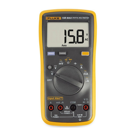
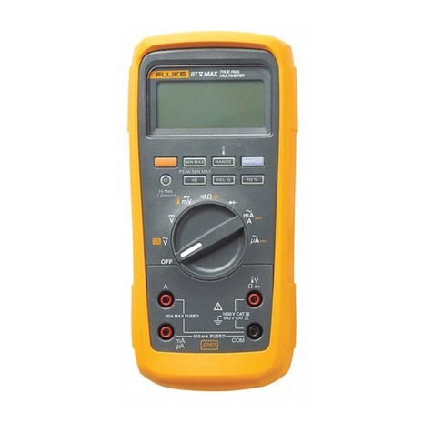
Fluke 88 V User manual

®
Model 88 V
Automotive Multimeter
Users Manual
99 Washington Street
Melrose, MA 02176
Fax 781-665-0780
TestEquipmentDepot.com

i
Table of Contents
Title Page
Introduction ........................................................................................................................ 1
Contacting Fluke................................................................................................................ 1
Safety Information.............................................................................................................. 1
The Meter's Features......................................................................................................... 5
Power-Up Options......................................................................................................... 13
Automatic Power-Off..................................................................................................... 13
Input AlertFeature ..................................................................................................... 13
Making Measurements ...................................................................................................... 14
Measuring AC and DC Voltage .................................................................................... 14
Measuring Temperature ............................................................................................... 15
Testing for Continuity.................................................................................................... 16
Measuring Resistance .................................................................................................. 18
Using Conductance for High Resistance or Leakage Tests........................................ 20
Measuring Capacitance................................................................................................ 21
Testing Diodes .............................................................................................................. 22
Measuring DC or AC Current ....................................................................................... 24
Measuring Frequency ................................................................................................... 27

Model 88 V
Users Manual
ii
Measuring Duty Cycle .................................................................................................. 29
Measuring Pulse Width................................................................................................. 30
Bar Graph .......................................................................................................................... 30
Zoom Mode (Power Up Option Only)........................................................................... 30
Uses for the Zoom Mode.............................................................................................. 31
HiRes Mode ....................................................................................................................... 31
MIN MAX Recording Mode ............................................................................................... 31
Smooth Feature (Power Up Option Only)......................................................................... 32
AutoHOLD Mode ............................................................................................................... 34
Relative Mode.................................................................................................................... 34
Using the Meter for Automotive Applications.................................................................... 34
Measuring RPM ............................................................................................................ 35
Testing MAP or BP/MAP Sensors with Frequency Output ......................................... 38
Measuring Internal Resistance of an Ignition Coil ....................................................... 40
Measuring Pulse Width on a Port Fuel Injector ........................................................... 42
Testing Ripple Voltage on an Alternator ...................................................................... 44
Measuring Voltages on a Typical Oxygen Sensor ...................................................... 46
Measuring Starter Circuit Voltage Drop ....................................................................... 48
Testing the Throttle Position Sensor Voltage .............................................................. 50
Testing the Throttle Position Sensor Resistance ........................................................ 50
Isolating a Circuit Causing a Current Drain ................................................................. 52
Measuring System Voltage .......................................................................................... 54
Testing for Continuity in a Switch................................................................................. 56
Maintenance ...................................................................................................................... 58
General Maintenance ................................................................................................... 58
Testing the Fuse ........................................................................................................... 58
Replacing the Battery ................................................................................................... 59
Replacing the Fuses..................................................................................................... 60

Contents
(continued)
iii
Service and Parts .............................................................................................................. 60
Specifications..................................................................................................................... 66
General Specifications.................................................................................................. 66
Detailed Specifications ................................................................................................. 67

v
List of Tables
Table Title Page
1. Electrical Symbols..................................................................................................................... 4
2. 88 V Automotive Multimeter Front Controls ............................................................................. 5
3. Input Terminals ......................................................................................................................... 6
4. Rotary Switch Positions ............................................................................................................ 7
5. Pushbuttons .............................................................................................................................. 8
6. Display Features ....................................................................................................................... 11
7. Functions and Trigger Levels for Frequency Measurements .................................................. 28
8. MIN MAX Functions .................................................................................................................. 33
9. Battery Charge Voltages........................................................................................................... 54
10. Replacement Parts.................................................................................................................... 62
11. Accessories ............................................................................................................................... 65
12. AC Voltage Function Specifications ......................................................................................... 67
13. DC Voltage, Resistance, and Conductance Function Specifications...................................... 68
14. Temperature Specifications ...................................................................................................... 68
15. Current Function Specifications................................................................................................ 69
16. Capacitance and Diode Function Specifications ..................................................................... 70
17. Frequency Counter Specifications ........................................................................................... 71

Model 88 V
Users Manual
vi
18. Frequency Counter Sensitivity and Trigger Levels.................................................................. 72
19. Electrical Characteristics of the Terminals............................................................................... 73
20. Min Max Recording Specifications ........................................................................................... 74

vii
List of Figures
Figure Title Page
1. 88 V Automotive Multimeter Front............................................................................................ 5
2. Measuring AC and DC Voltage ................................................................................................ 14
3. Testing for Continuity ................................................................................................................ 17
4. Measuring Resistance .............................................................................................................. 19
5. Measuring Capacitance ............................................................................................................ 21
6. Testing a Diode ......................................................................................................................... 23
7. Measuring Current .................................................................................................................... 26
8. Components of Duty Cycle Measurements.............................................................................. 29
9. Measuring RPM with Inductive Pickup..................................................................................... 37
10. Testing MAP or BP/MAP Sensors with Frequency Output...................................................... 39
11. Measuring Internal Resistance on an Ignition Coil .................................................................. 41
12. Measuring Pulse Width on a Port Fuel Injector........................................................................ 43
13. Testing Ripple Voltage on an Alternator .................................................................................. 45
14. Measuring Voltages on a Typical Oxygen Sensor................................................................... 47
15. Measuring Starter Circuit Voltage Drop ................................................................................... 49
16. Testing the Throttle Position Sensor Resistance..................................................................... 51
17. Isolating Circuit Causing Current Drain.................................................................................... 53

Model 88 V
Users Manual
viii
18. Measuring the No-Load Voltage of a Battery........................................................................... 55
19. Testing for Continuity in a Switch ............................................................................................. 57
20. Testing the Current Fuses ........................................................................................................ 59
21. Battery and Fuse Replacement................................................................................................ 61
22. Replaceable Parts..................................................................................................................... 64

Automotive Multimeter
Introduction
Introduction
XWWarning
Read "Safety Information" before you use the
Meter.
The Model 88 V Automotive Multimeter (“the Meter”) is a
hand-held, battery-operated measurement device used for
voltage, continuity, resistance, current, diode, capacitance,
frequency, temperature, RPM, pulse width, and duty cycle
measurements.
To register your product, visit register.fluke.com
Safety Information
The Meter complies with:
•EN61010-1:2001
•ANSI/ISA S82.01-2004
•CAN/CSA C22.2 No. 1010.1:2004
•UL61010-1
•Measurement Category III, 1000 V, Pollution
Degree 2
•Measurement Category IV, 600 V, Pollution
Degree 2
In this manual, a Warning identifies conditions and actions
that pose hazards to the user. A Caution identifies
conditions and actions that may damage the Meter or the
equipment under test.
Electrical symbols used on the Meter and in this manual
are explained in Table 1.
1

Model 88 V
Users Manual
2
XWWarning
To avoid possible electric shock or personal
injury, follow these guidelines:
•Use this Meter only as specified in this
manual or the protection provided by the
Meter might be impaired.
•Do not use the Meter if it is damaged.
Before you use the Meter, inspect the
case. Look for cracks or missing plastic.
Pay particular attention to the insulation
surrounding the connectors.
•Make sure the battery door is closed and
latched before operating the Meter.
•Replace the battery as soon as the
battery indicator (M) appears.
•Remove test leads from the Meter before
opening the battery door.
•Inspect the test leads for damaged
insulation or exposed metal. Check the
test leads for continuity. Replace
damaged test leads before you use the
Meter.
•Do not apply more than the rated voltage,
as marked on the Meter, between the
terminals or between any terminal and
earth ground.
•Never operate the Meter with the cover
removed or the case open.
•Use caution when working with voltages
above 30 V ac, 42 V ac peak, or 60 V dc.
These voltages pose a shock hazard.
•Use only the replacement fuses specified
by the manual.
•Use the proper terminals, function, and
range for measurements.
•Avoid working alone.
•When measuring current, turn off circuit
power before connecting the Meter in the
circuit. Remember to place the Meter in
series with the circuit.
•When making electrical connections,
connect the common test lead before
connecting the live test lead; when
disconnecting, disconnect the live test
lead before disconnecting the common
test lead.
•Do not use the Meter if it operates
abnormally. Protection may be impaired.
When in doubt, have the Meter serviced.
Test Equipment Depot - 800.517.8431 - 99 Washington Street Melrose, MA 02176
FAX 781.665.0780 - TestEquipmentDepot.com

Automotive Multimeter
Safety Information
•Do not operate the Meter around
explosive gas, vapor, or dust.
•Use only a single 9 V battery, properly
installed in the Meter case, to power the
Meter.
•When servicing the Meter, use only
specified replacement parts.
•When using probes, keep fingers
behind the finger guards on the
probes.
XWCaution
To avoid possible damage to the Meter or to
the equipment under test, follow these
guidelines:
•Disconnect circuit power and discharge
all high-voltage capacitors before testing
resistance, continuity, diodes, or
capacitance.
•Use the proper terminals, function, and
range for all measurements.
•Before measuring current, check the
Meter's fuses. (See "Testing the Fuse").
3

Model 88 V
Users Manual
4
Table 1. Electrical Symbols
BAC (Alternating Current) JEarth ground
FDC (Direct Current) IFuse
XHazardous voltage PConforms to European Union directives.
WRisk of Danger. Important information.
See Manual. $ Conforms to relevant Canadian Standards Association
directives.
M Battery. Low battery when displayed. TDouble insulated
RContinuity test or continuity beeper tone. E Capacitance
CAT
III
IEC Overvoltage Category III
CAT III equipment is designed to protect
against transients in equipment in fixed-
equipment installations, such as
distribution panels, feeders and short
branch circuits, and lighting systems in
large buildings.
CAT
IV
IEC Overvoltage Category IV
CAT IV equipment is designed to protect against
transients from the primary supply level, such as an
electricity meter or an overhead or underground utility
service.
tUnderwriters Laboratories GDiode
sInspected and licensed by TÜV Product Services.
Test Equipment Depot - 800.517.8431 - 99 Washington Street Melrose, MA 02176
FAX 781.665.0780 - TestEquipmentDepot.com

Automotive Multimeter
The Meter's Features
Tables 2 through 6 briefly describe the Meter's features.
MIN MAX RANGE
REL Hz %
AutoHOLD
A
mA
COM
400mA
FUSED
10A MAX
FUSED
A
88
3
2
1
4
ayg40f.eps
Figure 1. 88 V Automotive Multimeter Front
Table 2. 88 V Automotive Multimeter Front Controls
Number Description
ADisplay
BPushbuttons
CRotary Switch
DInput Terminals
5

Model 88 V
Users Manual
6
Table 3. Input Terminals
Terminal Description
A Input for 0 A to 10.00 A current measurements (20 A overload for 30 seconds maximum), current frequency,
duty cycle, and pulse width measurements.
mA
µ
A Input for 0 µA to 400 mA current measurements (600 mA for 18 hrs.), current frequency, duty cycle, and pulse
width.
COM Return terminal for all measurements.
I
RPM
Input for voltage, continuity, resistance, diode, capacitance, frequency, temperature, duty cycle, pulse width,
and RPM measurements.
Test Equipment Depot - 800.517.8431 - 99 Washington Street Melrose, MA 02176
FAX 781.665.0780 - TestEquipmentDepot.com

Automotive Multimeter
The Meter's Features
Table 4. Rotary Switch Positions
Switch Position Function
Any Position When the Meter is turned on, the Meter model number briefly appears on the display.
K AC voltage measurement
LDC voltage measurement
Press Afor RPM o, press again for RPM n.
600 mV dc voltage range
MPress Afor temperature (T).
Press Efor continuity test.
eResistance measurement
N
Press Afor capacitance measurement.
O Diode test
e DC current measurements from 0 mA to 10.00 A
Press Afor ac current measurements, from 0 mA to 10.00 A.
f DC current measurements from 0 µA to 6000 µA
Press Afor ac current measurements from 0 µA to 6000 µA.
7

Model 88 V
Users Manual
8
Table 5. Pushbuttons
Button Switch
Position Function
N Selects capacitance
M Selects temperature
g K L
Selects measurement of RPM oor RPM n
e Switches between dc and ac current
f Switches between dc and ac current
A
(Yellow)
Power-up Disables automatic power-off feature (Meter normally powers off in 30 minutes).
The Meter reads “PoFF” until Ais released.
B
Any switch
position
Power-up
Starts recording of minimum and maximum values and disables power-off feature. Steps the
display through MAX, MIN, AVG (average), and present readings. Cancels MIN MAX (hold for 1
second).
Enables the Meter’s calibration mode and prompts for a password.
The Meter reads “CAL“ and enters calibration mode. See
the 80 Series V Callibration Manual
for
more information.
Test Equipment Depot - 800.517.8431 - 99 Washington Street Melrose, MA 02176
FAX 781.665.0780 - TestEquipmentDepot.com

Automotive Multimeter
The Meter's Features
Table 5. Pushbuttons (cont.)
Button Switch
Position Function
Any switch
position Switches between the ranges available for the selected function. To return to autoranging, hold the
button down for 1 second.
MSwitches between °C and °F when temperature is selected.
C
Power-up Enables the Meter’s smoothing feature. The Meter reads “5___” until Cis released.
D
Any switch
position
MIN MAX
recording
Frequency
counter
Power-up
AutoHOLD captures the present reading on the display. When a new, stable reading is detected,
the Meter beeps and displays the new reading.
Stops and starts recording without erasing recorded values.
Stops and starts the frequency counter.
Turns on all LCD segments until D, is released.
H
Any switch
position
Power-up
Turns the backlight on, makes it brighter, and turns it off.
Hold Hdown for one second to enter the HiRes digit mode. The “HiRes” icon appears on the
display. To return to the 3-1/2 digit mode, hold Hdown for one second. HiRes=19,999
Changes the default ranging from manual to auto for the V ac and V dc functions.
The Meter reads “Avto” until His released.
9

Model 88 V
Users Manual
10
Table 5. Pushbuttons (cont.)
Button Switch
Position Function
E
Continuity
ReE
MIN MAX
recording
Hz, Duty
Cycle
Power-up
Turns the continuity beeper on and off
Switches between Peak (250 µs) and Normal (100 ms) response times.
Toggles the meter to trigger on positive or negative slope.
Disables the beeper for all functions. The Meter reads “bEEP” until Eis released.
F
(Relative
mode)
Any switch
position
Power-up
Stores the present reading as a reference for subsequent readings. The display is zeroed, and
the stored reading is subtracted from all subsequent readings.
Enables zoom mode for the bar graph. The Meter reads “2rEL” until Fis released.
G
Any switch
position
except
diode test
Power-up
Press Gfor frequency measurements.
Starts the frequency counter.
Press again to enter duty cycle mode, and again to measure pulse width (ms).
Enables the Meter’s high impedance mode when the mV dc function is used.
The Meter reads “Hi2” until Gis released.
Test Equipment Depot - 800.517.8431 - 99 Washington Street Melrose, MA 02176
FAX 781.665.0780 - TestEquipmentDepot.com

Automotive Multimeter
The Meter's Features
Table 6. Display Features
ayg04f.eps
Number Feature Indication
Y Polarity indicator for the
analog bar graph.
A
TrigY Positive or negative slope
indicator for Hz/duty cycle
triggering, pulse width, RPM.
B X The continuity beeper is on.
C W Relative (REL) mode is active.
Number Feature Indication
D a Smoothing is active.
E -Indicates negative readings. In
relative mode, this sign
indicates that the present input
is less than the stored
reference.
F ZIndicates the presence of a
high voltage input. Appears if
the input voltage is 30 V or
greater (ac or dc). Also
appears in cal, Hz, and duty
cycle modes.
G RS AutoHOLD is active.
H S Display Hold is active.
I p Indicates the Meter is in Peak
Min Max mode and the
response time is 250 µs.
J m
MAX MIN AVG Indicators for minimum-
maximum recording mode.
K b
The battery is low.
XWWarning: To avoid false
readings, which could lead to
possible electric shock or
personal injury, replace the
battery as soon as the battery
indicator appears.
11

Model 88 V
Users Manual
12
Number Feature Indication
A, µA, mA Amperes (amps), Microamp,
Milliamp
V, mV Volts, Millivolts
µF, nF Microfarad, Nanofarad
nS Nanosiemens
% Percent. Used for duty cycle
measurements.
ms Milliseconds. Used for pulse
width measurement.
e, Me, ke Ohm, Megohm, Kilohm
Hz, kHz Hertz, Kilohertz
L
AC DC Alternating current, direct
current
M °C, °F Degrees Celsius, Degrees
Fahrenheit
N 610000 mV Displays selected range
O HiRes The Meter is in high resolution
(Hi Res) mode. HiRes=19,999
Number Feature Indication
Auto
The Meter is in autorange
mode and automatically
selects the range with the best
resolution.
P
Manual The Meter is in manual range
mode.
Q
The number of segments is
relative to the full-scale value
of the selected range. In
normal operation 0 (zero) is on
the left. The polarity indicator
at the left of the graph
indicates the polarity of the
input. The graph does not
operate with the capacitance,
frequency counter functions,
temperature, or peak min max.
For more information, see “Bar
Graph” later in this manual.
The bar graph also has a
zoom function, as described
under "Zoom Mode".
R RPMon
oconventional (4 cycle)
Counts every other revolution.
nwaste spark or 2 cycle.
Counts every revolution.
Test Equipment Depot - 800.517.8431 - 99 Washington Street Melrose, MA 02176
FAX 781.665.0780 - TestEquipmentDepot.com
Other manuals for 88 V
1
Table of contents
Other Fluke Multimeter manuals

Fluke
Fluke 287 Use and care manual

Fluke
Fluke 233 User manual

Fluke
Fluke 88 V User manual

Fluke
Fluke 116C User manual

Fluke
Fluke 87V Ex User manual

Fluke
Fluke 80 Series III User manual

Fluke
Fluke 15B MAX Use and care manual
Fluke
Fluke 80 Series V User manual

Fluke
Fluke 175 User manual

Fluke
Fluke 233 User manual