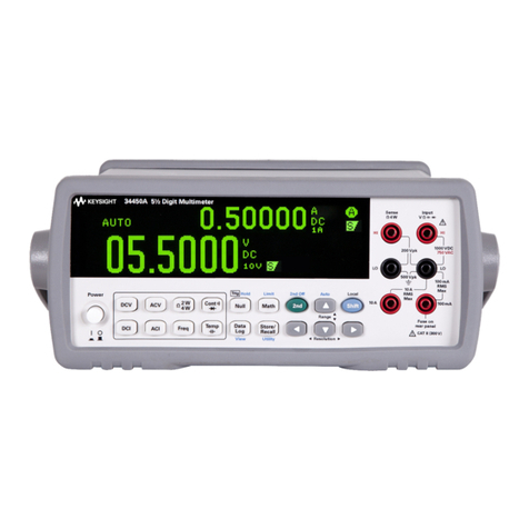
Fluke 8502A User manual

NOTE
This manual documents the Model 8502A Digital Multimeter and its
assemblies at the revision levels shown in Appendix 7A. If your
instrument contains assemblies with different revision tetters, it will be
necessary for you to either update or backdate this manual. Refer to the
supplemental change/errata sheet for newer assemblies, or to the
backdating sheet in Appendix 7A for older assemblies.
Instruction Manual
P/N 471466
March 1978

Notwithstanding any provision of any agreement the following warranty is exclusive:
The JOHN FLUKE MFG. CO,, INC., warrants each instrument it manufactures to be free from defects in materia! and
workmanship under normal use and service for the period of 1-year from date of purchase. This warranty extends only
to the original purchaser. This warranty shall not apply to fuses, disposable batteries (rechargeable type batteries are
warranted for 90-days), or any product or parts which have been subject to misuse, neglect, accident, or abnormal
conditions of operations,
in the event of failure of a product covered by this warranty, John Fluke Wfg, Co., Inc., will repair and calibrate an
instrument returned to an authorized Service Facility within 1year of the original purchase; provided the warrantor’s
examination discloses to its satisfaction that the product was defective. The warrantor may, at its option, replace the
product in lieuof repair. With regard to any instrument returned within 1year of the original purchase, said repairs or
replacement will be made without charge. If the failure has been caused by misuse, neglect, accident, or abnormal
conditions of operations, repairs wilt be billed at anominal cost. In such case, an estimate will be submitted before
work is started, if requested.
THE FOREGOING WARRANTY IS IN LIEU OF ALL OTHER WARRANTIES, EXPRESS OR IMPLIED,
INCLUDING BUT NOT LIMITED TO ANY IMPLIED WARRANTY OF MERCHANTABILITY, FITNESS,
OR ADEQUACY FOR ANY PARTICULAR PURPOSE OR USE, JOHN FLUKE MFG. CO.. INC., SHALL
NOT BE LIABLE FOR ANY SPECIAL, INCIDENTAL, OR CONSEQUENTIAL DAMAGES. WHETHER IN
CONTRACT, TORT, OR OTHERWISE.
If any failure occurs, the following steps should be taken:
1. Notify the JOHN FLUKE MFG. CO., INC., or nearest Service facility, giving full details of the difficulty, and
include the model number, type number, and serial number. On receipt of this information, service data, or
shipping instructions will be forwarded to you.
2. On receipt of the shipping instructions, forward the instrument, transportation prepaid. Repairs will be
made at the Service Facility and the instrument returned, transportation prepaid.
SHIPPING TO MANUFACTURER FOR REPAIR OR ADJUSTMENT
All shipments of JOHN FLUKE MFG. CO., INC,, instruments should be made via United Parcel Service or “Best Way”
prepaid. The instrument should be shipped in the original packing carton; or if it is not available, use any suitable
container that is rigid and of adequate size, (f asubstitute container is used, the instrument should be wrapped in paper
and surrounded with at least four inches of excelsior or similar shock-absorbing material.
CLAIM FOR DAMAGE IN SHIPMENT TO ORIGINAL PURCHASER
The instrument should be thoroughly inspected immediately upon original delivery to purchaser. All material in the
container should be checked against the enclosed packing list, The manufacturer will not be responsible for shortages
against the packing sheet unless notified immediately. If the instrument is damaged in anyway, aclaim should be filed
with the carrier immediately. (To obtain aquotation to repair shipment damage, contact the nearest Fluke Technical
Center.) Final claim and negotiations with the carrier must be completed by the customer.
The JOHN FLUKE MFG. CO,. INC, will be happy to answer all applications or use questions, which will enhance your
use of this instrument. Please address your requests or correspondence to: JOHN FLUKE MFG, CO.. INC,, P.O. BOX
43210, MOUNTLAKETERRACE, WASHINGTON 98043, ATTN: Sales Dept. For European Customers; Fluke (Holland)
B.V., P.O. Box 5053, 5004 EB, Tilburg, The Netherlands.
•For European customers. Air Freight prepaid.
John Fluke Mfg. Co., Inc., P.O. Box 43210, Mountlake Terrace, Washington 98043
Rev. 4/80

1-1. INTRODUCTION
1-2. This manual comprises eight modular sections. You
will find herein up-to-date information for installing, oper-
ating and maintaining the Fluke Model 8502A Digital
Multimeter. Generally, complete descriptions and instruc-
tions are provided for the 8502A mainframe, modules
necessary for DC Volts and DC Ratio measurement, and for
any optional modules (AC Converter, Ohms Converter, etc.)
that you may have ordered with your 8502A. Specifically,
each section contains:
1. Section 1—General description, specifications.
2. S«:tion 2—Operating instruction, capabilities.
3. Section 3~Theory of operation, including simplif-
ied schematic and functional block diagrams.
4. Section 4—Maintenance, adjustments and trouble-
shooting.
5. Section 5-List of replaceable parts, with parts
locators.
6. Section 6-Option and accessory information,
including complete information on any option
ordered with the 8502A. As the need arises to
broaden your 8502A*s capabilities, the most recent
information will be included with any options you
order.
7. Section 7—General information (list of abbrev-
iations, federal supply codes. Service Centers, and
Sales Respresentatives).
8. Section 8—Schematic diagrams.
1-a DESCRIPTION
1-4. The Model 8502A Digital Multimeter is a61/2
digit instrument employing microprocessor control and a
bus structure. Memory programming either from the front
panel or through aremote interface permits anumber of
operations to be performed on the measured input before
it is displayed. The standard configuration allows for mea
surement of dc volts in 5ranges. Four ranges are available
for ac volts when either optional ac converter is installed.
Resistance can be measured in 8ranges. Current can be
measured in 5ranges.
1-5. Modular Construction
1-6. Considerable versatility is realized through the
8502A’s unique constructicm. All active components are
contained in modules which plug into amainframe mother-
board. This module-motherboard mating, combined with
bus architecture and microprocessor control, yields both
ease of option selection and reduced downtime.
1-7. Microprocessor Control
1-8. All modules function under direct control of a
microprocessor based controller. Each module is addressed
by the controller as a memory location. External reference
values and offsets can be applied separately, stored in mem-
ory, and automatically used as factors in all subsequent
readings. Digital filtering utilizes averaged samples for each
reading.
1-9. Recirculating Remainder A/D Conversion
1-10. The 8502A adapts Fluke’s patented recirculating
remainder (R^) A/D conversion technique to micropro-
cessor control. This combination provides fast, accurate
linear measurements and long-term stability.

8502A
1-11. 0ptions and Accessories
1-12. Remote interfaces, AC converters, acurrent con-
verter and an ohms converter are among the numerous
options and accessories available for the 8502A. Refer to
Tables 1-1 and 1-2 for complete listings. AC conversion can
be accomplished with eidier an ac averaging module (-01)
or atrue RMS module (—09A). Any one of three remote
interface modules (—05, —06, —07) may be installed at one
time; the isolator module (—08A) must then be installed to
maintain guarding of analog and high quality busses during
remote operations. Maximum interfacing with digital sys-
tems is thus realized. Calibration downtime is reduced
through the use of acalibration memory module (-04);
correction factors may be entered from the front panel,
providing automatic correction for further measurements.
Table 1-1. 8502A Options
Option IMo. Name Notes
01 AC/DC Converter (Averaging) 1,3
02 Ohms Converter
03 Current Shunts 3
04 Calibration Memory
05 IEEE Standard 488-1975 Interface 2
06 Bit Serial Asynchronous interface 2
07 Parallel Interface 2
08A Isolator 4
09A AC/DC Converter (True RMS) 1, 3
16 Front—Rear Switchabie Input 5
17 Rear Input
1} Options 01 and 09A cannot be
installed simultaneously.
2) Only one of Options 05, 06, and 07
can be installed at any time.
3) For die AC portion of Option 03 to
operate, either Option 01 or 09A
must be installed.
4) Option 08A must be installed for
remote operations.
5} Option 16 must be factory installed.
1-2
Analog inputs from aremote position are permitted when
Rear Input (Option— 17) is installed. Selectable front or
rear analog inputs are available with Option —16.
1-13. SPECIFICATIONS
1-14. Mainframe specifications with DC Volts and DC
Ratio measurement capability are presented in Table 1-3.
Optional functirjn specifications are supplied with the
respective option modules and included in Section 6. The
table of specifications presented here is divided into three
parts:
1.General Specifications.
2. Accuracy.
3. Instrument Operating Characteristics.
Table 1-2. 8502A Accessories
Model or
Part No. Name
M04-205-600 Rack Ear Mounting Assembly
MOO-260-010 18-inch Rack Slides
MOO-280-610 24-inch Rack Slides
80F-5 Fligh Voltage Probe
80F-15 High Voltage Probe
81RF High Frequency Probe
82RF High Frequency Probe
KDM1 Keyboard Display Module w/Cable
Y8001 IEEE Std. Cable, 1Meter Length
Y8002 IEEE Std. Cable, 2Meter Length
Y8003 IEEE Std. Cable, 4Meter Length
MIS-7011K* Extender Assembly
MIS-7190K* Static Controller
M!S-7191K* Test Module
MIS-7013K* Bus Interconnect and Monitor
*For use during service or repair

TEMPERATURE RANGE
Operating O^C to 50*C
Non Operating -40°C to 70°C*
*0’^ Cto 50^C operating and non-operating with
calibration memory option (
-
04) installed.
HUMIDITY RANGE
(Operating to Full Accuracy)
0‘^C to 18°C 80% RH
18“C to 40'^C 75% RH
40‘'C to 5(fC 60% RH
OVERLOAD
LO to Guard 127 Vmax
Guard to Chassis 1000V max
HI Sense to Hi Source 127V max
LO Sense to LO Swrce 127V max
HI Sense to LO Sense 1000V max
HI Source to LO Source 280V max
cm
Inches
DIMENSIONS
HLW
10.8 X42.5 X43.2
4.25 X16.75 X17
WEIGHT
Basic Fully Loaded
kg 9.1 10.92
Lbs 20 24
OPERATING POWER
Basic instrument 12 watts 115V ac or 230V ac ±10%
Fully Loaded 24 watts 50-60 Hz
WARM-UP
1hour to rated accuracy
SHOCK AND VIBRATION
Meets requirements of MIL-T-28800 for Class 5
style Eequipment.
Note
The stated accuracies are valid under the following environ-
mental conditions.
Temperature: 18'^Cto 28°C (Except 24 hour: 22'^Cto24°C}
Humidity: <=75%
Line Regulation: 90V to IIOV. 103.5Vto 126.5V, or 207V
to 253V @45 to 66 Hz
DC Volts Normal Resolution (5 1/2 digits)
Full Scale
Accuracy ±(®^0 of Input +Number of Digits)
Range Resulu tiuii 24 Hours 90 Days 1Year
100 mV 312 mV 1uV 0.002+4 0.003 +50.005 +8
1V2.5 V10 uV 0.001 +10,002 +10.004 +1
10 V20 V100uV 0.001 or 1* 0.001 +10.002 +1
100 V160 V1mV 0.001 +10.002 +10.004 +1
1000 V1200 V
*Whichever is greater.
1
10 mV 0.001 +10.002 +10.004 +1

DC Volts
(Continued)
High Resolution (HI RES or CAL —61/2 digits)
Range Full Scale Resolution Accuracy ±(% of Input +Number of Digits)
24 Hours 90 Days 1Year
1V2.5 V1uV 0.001 +60.002 +80.004 +9
10 V20 V lOuV 0.001 or 6* 0.001 +80.002 +9
100 V160 V100 uV 0.001 +6 0.002 +80.004 +9
1000 V1200 V1mV 0.001 +6 0.002 +80.004 +9
*Whicheve is greater.
DC Ratio
Ext. Ref. Voltage Accuracy
+20V to+40V +(A +B+10 ppm)
+V .*to+2QV 4A+B+2f
—min. —^Txrefl '
A=WV dc Range Accuracy
B-Input Signal Function and Range Accuracy
V.^!^ ^Minimum Allowable External Reference Voltage
=>Ad50/tyfe Value of Ex^rna! Reference Voltage
*The formula for determining is included in Instrument Operating Characteristics
Example Calculations for External Reference Accuracy;
1. Input =+90.000V, Ext. Ref. Input =30.000V (+ 15V to Ext. Ref. HI. -15V to Ext. Ref. LO)
A=.001%+ 1Digit B=.001% +1Digit
Ratio Accuracy =+(A +B+10 ppm) =+{.001% +1Digit +.001%+1 Digit +.001% -+(.CK)3% +2 Digits)
Reading may be between 3.0003 and 2.9997
2. Input =1.20000V, Ext. Ref. Input =.12000 (V^.^ for IV Range)
A== .001% +1Diqit, B=.001% +1Digit, 200pDm .02%
Vxref -12
Ratio Accuracy =+.001% +1Digit +.001% +1 Digit +.1667%) =+{.1687%+ 2Digits)
Reading may be between .998313 and 1.001686.
INSTRUMENT OPERATING CHARACTERISTICS
DC Volts TEMPERATURE COEFFICIENT
(0°C to 18°C and 28°C to 50°C) INPUT IMPEDANCE
Range Temperature Coefficient Range input Impedance
100 mV ±(3 ppm/reading +0.5 digit)/°C 100 mV >10,000 MQ,
IV ±(3 ppm/reading +0.1 digit)/ °C IV >10,000 mi
10 V±(2 ppm/reading +0.05 digit)/'^C* 10 V>10,000
100 V±(3 ppm/reading +0.1 digit)/'^C* 100 V10
1000 V±{3 ppm/reading +0.05 digit)/°C* 1000 V10 mH
'For High Resolution Multiply Digits by 10. Guard to Chassis CO
INPUT BIAS CURRENT
Bias Current <±5 pA
30 Days {23'^C ±Tc)
<±50 pA
Temperature Coefficient
±3pA/°C

8502^
CHARACTERISTICS (Continued)
DC Volts
(Continued)
RESPONSE TIME
Analog Settling Time Within Voltmeter
Reading Rate
50 Hz line 4Samt
60 Hz line
4Samples/Rdg
32 Samples/Rdg
128 Samples/Rdg
4Samples/Rdg
32 Samples/Rdg
128 Samples/Rdg
22 ms
162 ms
642 ms
18 ms
136 ms
546 ms
Filter Mode
Filter, Fast
Bypass
Bypass
Filter, Slow
Bypass
Bypass
Step input to
0.01% of Change
40
2
2
400 ms
2ms
2ms
Step Input to
0.001% of Change
50
20
20
500
20
20
II
*Numher of samples per reading is programmable
from I(2°) to 131,072 (2^ '^) in 18 binary steps.
ZERO STABILITY OVERLOAD
Better than 5juV for 90 days after aone hr. warm-
up. Front Panel pushbutton auto zero is provided.
The zero correction is stored in memory until
power is interrupted or the 8502A is RESET.
If calibration memory Option --04 is installed, the
zero correction is retained.
±1200V DC, 1200V peak to 60 Hz, or 1400V peak
above 60 Hz may be applied continuously to any
dc range without permanent damage. Maximum
common mode rate of voltage rise is 1000V//usec.
50 Hz
Fast Filter
50 Hz
Slow Filter
60 Hz
Fast Filter
60 Hz
Slow Filter
90 dB
95 dB
100 dB
100 dB at
60 Hz for
1KO un-
balance
Sum of
Common
Mode Re-
jection
and Nor-
mal Mode
Rejection
128 SAMPLES/READING
Typical Performance with 60 Hz Line
(Combined digital and analog filtering)
Cusps shown are at multiples of 60 Hz line frequency.
Similar cusps (not shown} occur every VA Hz.
Slow Filter
Fast Filter
-40 dB
-100 dB
-120 dB 10 100 240 1K
F(Hz)-^

8502A
Table 1-3. Specifications (Cont)
JNSTRUMEMT OPERATING CHARACTERfSTfCS (Continued)
!DC Ratio 1INPUT IMPEDANCE SOURCE IMPEDANCE
Ext Ref HI or LO >10,000 relative to Ohms Resistive Unbalance (Ext Ref HI to LO) <4
;Guard* or Sense LO
j
1
Total Resistance Sense LO from either HI or LO
<20 kCl
BIAS CURRENT OVERLOAD (Ext Ref HI or LO)
iExt Ref HI or LO relative to Ohms Guard* or ±180 volts peak ,127V rms (relative to Ohms
Sense LO <5 nA Guard* or Sense LO) X(360V peak Hi to LO)
t
*Ohms Guard available through rear input (-16 or -17 Option)
NOISE REJECTION
Normal Mode Common Mode, All Inputs Driven
Sense Input—Same as dc volts
Ext Ref Input—dc, line frequency and 2x line freq-
uency >100 dB
Sense input—Same as dc volts
Ext Ref Input—Line frequency and 2x line frequen-
cy, 75 dB
Settling Time
Sense Input Fast Filter <50 ms to 0.001% of change
Sense Input Slow Filter <500 ms to 0.001% of change
Digitizing Time NOTE
The Sense Input is measured prior to measur-
ing Ext Ref HI and L0.
Ext Ref Input-Each input Hi and LO
90 ms at 60 Hz line frequency
107 ms at 50 Hz line frequency
Ext Ref Calibration—1 2ms
EXT REF VOLTAGE RANGE
Maximum Ext Ref Voltage =±40V between Ext Ref HI and LO terminals, providing neither ter-
minal is greater than ±20V relative to the Sense LO or Ohms Guard
terminals.
Minimum Ext Ref Voltage =±0.0001 V, or (whichever is greater)
10^
MAXIMUM DISPLAY- Ratio. Scaling or Offset Mode =±1.00000 x10^ in all Ranges
Sense Input
Approx. Digitizing
Rdg. Rate Time
60 Hz 4Va rdg/s 136 ms
1Vi rdg/s 536 ms
50 Hz SVa rdg/s
1Va. rdg/s
162 ms
642 ms
60 Hz 4samples/rdg 18 ms
50 Hz 4samples/rdg 22 ms

Some semiconductors and custom IC’s can be
damaged by electrostatic discharge during
handling. This notice explains how you can
minimize the chances of destroying such devices
by:
1. Knowing that there is aproblem.
2. Learning the guidelines for handling them.
3. Using the procedures, and packaging and
bench techniques that are recommended.
The Static Sensitive (S.S.) devices are identified in the Fluke technical manual parts list with the symbol
The following practices should be followed to minimize damage to S.S. devices.
2. KEEP PARTS IN ORIGINAL CONTAINERS
UNTIL READY FOR USE. 4. HANDLE S.S. DEVICES BY THE BODY

5. USE ANTI-STATIC CONTAINERS FOR
HANDLING AND TRANSPORT
6. DO NOT SLIDE S.S. DEVICES OVER
ANY SURFACE
8.
HANDLE S.S. DEVICES ONLY AT A
STATIC-FREE WORK STATION
ZA
9. ONLY ANTI-STATIC TYPE SOLDER-
SUCKERS SHOULD BE USED.
10. ONLY GROUNDED TIP SOLDERING
IRONS SHOULD BE USED.
Anti-static bags, for storing S.S. devices or pcbs
with these devices on them, can be ordered from the
John Fluke Mfg. Co., Inc.. See section 5in any Fluke
technical manual for ordering instructions. Use the
following part numbers when ordering these special
bags.
John Fluke Bag Size
Part No.
453522 6” X8"
453530 8"x12”
453548 16” X24"
454025 12” X15”

2-1. INTRODUCTION WARNING
2-2. Installation and operation of the 8502A Digital
Multimeter are explained in this section. The 8502A’s full
capabilities may be realized by thoroughly reading and
understanding these operating instructions. Explanations
and applications are provided for all standard functions and
operations. Read them. Should any difficulties arise,
contact your nearest Fluke Sales Representative (list in
Section 7), or the John Fluke Mfg. Co., Inc. (P.O. Box
43210, Mountlake Terrace, Wa., 98043; tel, 206 774-221 1).
2-3, SHIPPING INFORMATION
24. The 8502A is packaged and shipped in afoam-
packed container. Upon receipt of the instrument, athor-
ough inspection should be made to reveal any possible
shipping damage. Special instructions for inspection and
claims are included with the shipping container.
2-5. If reshipment is necessary, the original container
should be used. If the original container is not available,
anew container can be obtained from John Fluke Mfg. Co.,
Inc. Please reference the instrument model number when
requesting anew shipping container.
2-6. INSTALLATION
2-7. Non-marring feet and atilt-down bail are installed
on the instrument for field or bench use. Arack-mounting
kit and rack slides are available for use with standard 19-inch
equipment racks. Information regarding installation or rack-
mounting accessories Is contained in Section 6.
2-8. The 8502A operates from either 115V ac ±10%
or 230V ac ±10%, 50 or 60 Hz (10% tolerance translates
to high and low limits of: 103.5 to 126.5V ac, 207 to
253V ac).
TO AVOID ELECTRICALSHOCK, PROPERLY
GROUND THE CHASSIS. AGROUND CON-
NECTION IS PROVIDED IN THE THREE-
PRONG POWER CONNECTOR; IF PROPER
GROUND IN YOUR POWER SYSTEM IS IN
DOUBT, MAKE ASEPARATE GROUND CON-
NECTION TO THE REAR PANEL CHASSIS
BINDING POST. OTHERWISE, THE POSSIB-
ILITY OF ELECTRICAL SHOCK MAY EXIST
IF HIGH VOLTAGE IS MEASURED WITH
THE LEADS REVERSED (INPUT HI
GROUNDED).
2-9. OPERATING FEATURES
2-10. Display, control, and terminal locations on the
8502A can be found in Figure 2-1. Table 2-1, will then
detail respective functions. In addition, aconvenient set
of condensed operating instructions is provided under the
instrument’s front right side. Just puli out the tab.
2-11. OPERATING NOTES
2-12. Input Power
2-13. Abinding post on the rear panel has been provided
as an earth ground connection. Power supply switching
(il5V or 230V ac) is explained in Section 4. With the
exception of slower reading rates and filter time outs, oper-
ation at 50 Hz is identical to that at 60 Hz.
2-14. The line fuse (.5A MDL Slow Blow) is located on
the rear panel, near the heatsink. The current protection
fuse (1 .5A AGC) is located in the lower right-hand corner
of the front panel.
2-1

Table 2*1 .8502A Controls and Indicators
REF. NAME FUNCTION
NO.
1Digit Display Displays 51/2 digits with polarity and properly positioned decimal
point. When instrument is in Hi Res mode, the exponent display will
be used as an extra digit (for 61/2 digits).
2Exponent Display Displays polarity and value of exponent for engineering notation.
3Range and Function
indicators
LED's illuminate to identify function and autoranging selection.
4FUNCTION Controls Push to select volts (VDC, VAC), current (A DC, AAC), or OHMS.
Serve as dual function controls for numeric entries.
2-2

8502/!
Table 2-1. 8502A Controls and indicators (cont)
REF. NAME FUNCTION
NO.
5RANGE Controls Manually shift range up or down. Enter high resolution mode. Select
6MEMORY Controls
auto or manual ranging. Recall (HI, LO) peak or limit. Store (HI, LO)
limit values. Serve as dual function controls for numeric entries.
Toggle into/out of LIMITS, PEAK, CAL, OFFSET or SCALING.
7INPUT Terminals
RECALL Memory values. Manual TRIGGER. STORE applied values,
numerics. ENTER or clear (CE) numerics.
SENSE INPUT HI and LO for volts, ohms. INPUT SOURCE HI and
8(REAR INPUT IN)
LO for amps, ohms. Guard Current protection fuse. GUARD.
Optional (-16)
9Current Fuse Use AGC 1.5A
10 MODIFIER Controls RESET
11 Status Display
RESUME
REMOTE
EXT REF
FILTER
SAMPLE
Numerics
LED's light for;
12 Power Switch
Slow filter
Sample (flashes at reading rate)
SCALING selected
REMOTE selected
OFFSET selected
PEAK selected
LED's flash if CAL or EXT REF selected
Push on/Push off
13 (Rear Input Connector Optional connections for remote input and external reference
and Fuse) terminals (—16, -17).
14 (External Trigger Input) Optional (-08A)
15 (Interface Connectors and Optional remote interface module accessible in this area (—05, —06,
Switches) -07)
16 Power Connector Three-prong connector accepting line cord with ground wire.
17 Line Fuse Use MDL .5A (slow blow).
18 Chassis Ground Binding post for ground interconnections.
19 External Reference Terminals Apply external reference voltage. (40V max between HI and LO).

NOTE
2-16. DESCRIPTION
2-17.^ The 8502A’s display consists of adigit readout,
exponent, and LED annunciators for indication of instru-
ment function and status. Spedtlcaiiy, these features prtv-
vide:
]. 51/2 or 61/2 digit display with polarity, auto-
matic reading and decimal placement.
2. Exponent display with polarity for readings in
engineering notation. Serves as an extra digit of res-
olution in Hi Res and Ca! modes,
3. Function and autoranging indicators light for
function selected and for autoranging.
4. Status indicators give aconstant illumination to
signify selection of REMOTE, OFFSET, PEAK,
SCALING, slow FILTER. Dual function LED’s
will flash to indicate selection of CAL or EXT REF.
SAMPLE LEDwill flash at the reading rate selected
(with more than 128 samples per reading, the LED
will flash at the same rate to denote areading in
progress).
5.Power ON LED.
2-18 .WARNING INFORMATION
2-19. The digit and exponent displays will provide
warning indications and error codes.
1. “HHHHHH” will flash at the reading rate if the
input voltage exceeds the full scale value for the
range selected. Full scale values are included with
the specifications in Section 1.
2. “H” will flash in the exponent display should an
input voltage greater than 40V occur when in the
Scaling, External Reference or Offset modes.
3. These flashing indications will not be seen when in
the Cal mode.
NOTE
Flashing indicators in the digit or exponent
display are awarning only; they have no effect
on instrument operation.
4. Error codes will be provided in the digit and expon-
ent displays when appropriate. Consult Table 2-2
for applicable meanings.
Error codes will not be displayed in Cal mode.
Random, readings will then be the only indic-
ation of an invalid fiinction or faulty module.
Table 2-2. Error Codes
CODES FAULT
Error System error -if this error message appears prior to
the introductory messages at power initialization or
reset, the problem is with the calibration memory
module.
Error 0VDC/Ohm Zero Error -either aVDC/Ohm Zero was
attempted in arange other than 100 mV or 10 ohms,
or an overrange was entered.
Error IStore during overload condition attempted.
Error 2Filter module error —the module is faulty or not
installed.
Error 3 pc Signal Conditioner error —the module is faulty
or not installed.
Error 4Ohms or Current error —excessive voltage applied to
the selected module, shorting links not properly con-
nected, or the selected module is faulty.
Error 5RA/D error —the recirculating remainder analog to
digital converter module is faulty or not installed.
Error 6Numeriedisplay ovwflow error.
Error 7External Referen(» error —the magnitude of one of
the external reference inputs is greater than 20V dc.
Error 8Controller error —the module is faulty or not
installed.
Error 9Function Selection error —the function module sel-
ected, other than dc volts, is faulty or not installed.
Error CInvalid switch sequence during Recall or Store oper-
ations.
2-20. SPECIAL CONSIDERATIONS
2-21. Cal
2-22. Use of the Cal mode will significantly change nor-
mal display indications. As noted above, no warning indic-
ations will be displayed. Further, the exponent display will
now serve as an extra digit of resolution (yielding 61/2
digit resolution).
2-23. Hi Res
2-24- The exponent display will be used as an extra digit
of resolution in the High Resolution mode (not used in the
100 mV or 100 uA ranges). No exponent will be displayed.
2-4

Although not visible in Hi Res, the exponent remains in
effect; care should be exercised when interpreting readings.
To avoid confusion, remember that an exponent in the
exponent display will always have its own polarity sign; a
high resolution digit will not.
2'25. Input Terminals
2-26. TERMINAL INTERCONNECTIONS
2-30. Correct use of the 8502A’s guard terminal will
both protect the instrument and provide more accurate
readings. Since the LO to GUARD maximum voltage rating
is 127V, the guard terminal should always be connected
either to the INPUT LO terminal or to a point in the source
circuit to be measured. For accurate readings, connect the
guard to minimize common mode currents flowing through
any resistance which helps determine the voltage being mea-
sured. See Figure 2-3, for su^ested guard connections.
2-27. For dc voltage measurements, both INPUT HI
terminals may be left strapped together, The INPUT LO
terminals may likewise remain strapped. For most mea-
surements, it is sufficient to strap GUARD to INPUT LO.
Refer to Figure 2-2, for recommended input terminal
strapping.
CAUTfOIM
The guard terminal should not be left dis-
connected. Instrument damage can occur if
common mode voltage exceeds the LO to
GUARD maximum voltage rating (127V).
Figure 2-2. Front Panel Terminal Interconnections
2-28. GUARDING
2-31. Generally, guarding should be used in the following
situations:
I
.
When long signal leads are used.
2-29. Common mode voltages, resulting from currents
and voltage drops between two points otherwise electrically
common, may produce significant errors. Proper use of a
floating, guarded voltmeter will minimize these errors and
allow representative reading of normal mode voltages (actual
source voltage and noise).
2. When signal source impedance is high.
3. When making measurements near high-level radi-
ated no^e, particularly at the power line fre-
quency.
4. When making floating measurements.

8502A
NOTE
Errors due to thermal EMF’s should be consid-
ered when making low level, high resolution
measurements. Thermal EMF’s (voltages pro-
duced by temperature differences between con-
tacts of two dissimilar metals or by temper-
ature gradients along alength of material) may
cause differences in potential of several micro-
volts. Since the 8502A utilizes gold-plated
input terminals, the use of low EMF, shielded
cables with gold-plated spade lugs will minim-
ize thermal EMFerrors.
2-32. Front Panel Controls
2-33. Most front panel controls are momentary contact
switches. If held in continuously, such switches will be read
only one time. In addition, some of these switches will hold
aparticular reading in the 8502A’s display for as long as
they are held depressed. Front panel switches may have
1,2, or 3functions; switch sequencing will determine wliich
function is in effect for multi-function switches. Refer to
“OPERATING DIRECTIONS” later in this section for
detailed front pane! control procedures.
2-34. Function
2-35. The DC volts function is standard with this instru-
ment; optional modules must be included for all other
functions. Complete information for any options included
with your 8502A can be found in Section 6of this manual.
If afunction is selected for which the appropriate module
is not installed, “Error 9” will appear in the display.
2-30. Range
2-37. DC volts can be measured on five successive ranges
from 100 mV to 1(X)0V. Respective resolutions vary from
1uV to 1mV. Input impedance on the lOOV and lOOOV
ranges is 10 Mohms. On the lower three ranges it is greater
than 10,000 Mohms. Overrange capabilities, DC voltage
accuracies, and overload protection conditions are detailed
in Section 1of this manual.
2-38. Modifiers
2-39. FILTER
2-40, The 8502A has five filter modes.
1.F—slow filter, no time out —FILTER LED on.
2. FO —fast filter, no time out.
3. FI —filter bypass.
4. F2 —slow filter, with time out (550 msec, settling
time) -FILTER LED on.
5.
F3 -fast filter, with time out (50 msec, settling
time).
(“Fast” and “slow” refer to the respective filter’s settling
time.)
2-41. The slow filter will provide better line frequency
rejection; the fast filter discriminates against higher fre-
quency and harmonically related line noise. Time outs are
always inserted before the first reading is taken in anewly
selected function or range. With F2 or F3 selected, time
outs will always be inserted before each subsequent reading
in that function or range.
2-42. SAMPLE
2-43. Samples taken in the 8502Acan be synchronous
or asynchronous to the line frequency. Line frequency
noise rejection can be increased by averaging more samples
per displayed reading (refer to NOISE REJECTION specif-
ications in Table 1-3 of this manual.) Provision is therefore
made to change the number of samples taken for each
reading (display update). Setting the samples per reading
will yield aspecific reading time. Additional time per read-
ing will be necessary whenever memoo' operations (Offset,
Scaling, etc.) are involved. Ohms measurements will also
require more time due to the multiple readings involved.
2-44. For example, if rate 7is selected, 128 samples will
be taken and averaged per reading. With no memory oper-
ations involved, digitizing time for a dc volts reading will
therefore take 533 ms. Sample rate designations (such as 7)
are actually the number of samples per reading expressed as
exponents of 2; rate 1- ~ 128 samples per reading.
2-45. EXTERNAL REFERENCE
2-46. An external reference dc voltage can be used to
divide the inputs in any function. Atrue ratio measurement
is then computed by the Controller.
Input
Reading =
dc Ext. Ref. Input
2-47. Apair of external reference terminals will be
found either separately on the rear panel or together in
the optional rear input connector.
].The applied external reference voltage may be a
maximum of ±20V at either external reference HI
or LO or 40V between HI and LO, with respect to
SENSE LO (or to Ohms Guard in the rear input
connector).
2-6

8502A
2. Hie minimum voltage applicable to the externa!
reference terminals is the greater of either ±100 uV,
ora value found with the following formula:
Vmin =±iVjn I
10^
3. The resistance between either EXT REF terminal
and INPUT LO should be less than 20 Kohms.
Normally, EXT REF LO will be tied to INPUT LO.
2-48. REMOTE
249. If an optional remote interface is installed, the
REMOTE switch may be used to toggle into or out of
remote control. With the IEEE (Option —05) Interface
installed, only toggUng out of remote control is permitted
from the front panel. When in remote control, only the
remote switch and the power switch will have any effect on
the instrument’s operation. Areset caused by power inter-
ruption will return the instrument to local control.
2-50. Remote control does not affect analog inputs on
the High Quality Bus. With Rear Input (Option -17) or
Switchable Front -Rear Inputs (Option -16), separate
Sense Hi and Lo, Source Hi and Lo, Guard, Ohms Guard,
and External Reference connections must be made remotely.
2-51. Memory
2-52. The 8502A provides considerable versatility in
measurement manipulations through both front panel and
remote programming. Displayed numbers are computed
from measured data according to the following general
equation, where:
y=the displayed number
m=the scaling factor or external reference
X=the actual input (averaged samples)
b=the offset factor (subtracted)
2-53. Either displayed values or numeric sequences may
be stored as memory factors.
NOTE
Storing avalue in memory does not select a
mathematical operation. The operation must be
selected separately before or after the value is
stored.
2-54. LIMITS
2-55. Any currently displayed value may be stored as a
limit value. Withsuch values stored as references, the 8502A
(toggled into the limits mode) will yield adisplay of;
1. HI if the reading is greater than the high limit.
2. PASS if the reading is less than or equal to the
high limit and greater than or equal to the low
limit.
3. LO if the reading is less than the low limit,
NOTE
HI, LO, and PASS describe the normally dis-
played reading, with all math operations com-
pleted, relative to the limit values.
2-56. Only one set of limits may be stored at atime. A
function change will exit the Limits mode but retain stored
values.
2-57. PEAK
2-58. Highest and lowest values displayed in any series
of measurements may be stored when in the Peak mode.
Toggle in and out of this mode by depressing the PEAK
switch. Peak values will be retained after the mode is deact-
ivated but lost should the instrument be reset or the mode
re selected.
2-59. CALIBRATION MODE
2^60. The CAL switch will be found on the front panel
behind asmall plastic cover which pulls out and hinges
down. Sliding the switch down places the 8502A in the
Calibration mode. This mode is designed primarily to be
used with the Calibration Memory (Option —04). When
this module is installed and the instrument is in the Cal-
ibration mode, correction factors can be stored at the
decade point for each range and function. Refer to Section 6
of this manual for complete Calibration Memory procedures.
2-61. If the Calibration Memory is installed, inadvertent
use of the STORE switch will store the last reading as acal-
ibration factor and erase calibration factors for the function
and range in use at the time. To correct this possible mistake
without acalibration standard, disconnect the input, short
the input terminals, and press STORE again.
2-62. Whether or not the Calibration Memory module is
installed, entry into the Calibration mode (CAL LED
flashes) necessitates consideration of the following alter-
ations to the 8502A’s display:
2-7

8502A
1.The exponent is replaced with an extra digit of res-
olution.
2. Error codes are disabled. Only spurious readings
will now denote selection of an invalid function.
3. The overrange indication is disabled.
NOTE
When changing from one function .to another,
or upon entering the Cal mode, memory modes
will be deactivated. Stored values will be
retained. Use of RESET or interruption of
power to the 8502A will erase memory entries.
2-63. OFFSET
2-64. The Offset mode can be used to automatically sub-
tract anumber from the measured input and display the
result. The subtracted offset number may be:
1.Any currently displayed value
.
2. Aprogrammed numeric entry (ranging from +10^
to -10^).
2-65. The displayed reading in Offset mode will exliibit
no increase in digit resolution. Only one offset factor at a
time can be stored. Afunction change will deactivate Offset
mode; the stored value will be retained. Aflashing Hwill
appear in the exponent display should more than 40V
appear between the input terminals when in Offset mode.
2-66. SCALING
2-67. The Scaling mode may be used to automatically
divide ameasured input by aprogrammed number or by an
applied value. This feature essentially provides the ability to
program an external reference without standard external
reference limitations in range, in fact, scaling values may
range from +10^ to +10'® and from -lO^to —10"®. A
scaling factor of 0is not allowed. Scaled readings will con-
tain 3significant digits if the original reading had 3 or less
significant digits. For more than 3significant digits in the
original reading, the scaled reading will display the same
number of significant digits. Only one scaling factor may be
stored at a time. Afunction change will deactivate the
Scaling mode but retain the stored factor.
NOTE
If the 8502A is in both Scaling and Offset,
the scaling factor will be applied first; the
scaled displayed values will then be offset.
2-68. ZEROING
2-69. There are two methods of zeroing the 8502A.
Either method may be used in the 100 mV range or the
10ohm range
.
2-70. VDC/Ohms Zero
2-71. Correction for internal dc drift can be made by
applying agood quality, low thermal short between HI and
LO terminals (not between test leads). If necessary, repeat
this operation once the instrument has warmed up. Only
dc volts zero factors may be recalled.
2-72. Zeroing with OFFSET
2-73. After zeroing for internal drift, separate dc volts
and 2-wire ohms measurement corrections can be made by
shorting the test leads and storing the reading as an offset
factor.
2-74. Systems Use of the 8502A
2-75. The availability of optional interface modules
makes the 8502A adaptable to alarge variety of digital sys-
tems. Operating and programming instructions related to
remote operation are included with the appropriate optional
module. Overall information on remote interfacing can be
found in Fluke Application Bulletin —25 “System Use of
the Fluke Model 8500A”, Specific information about the
IEEE interface (-05 Option) may be found in Fluke Appli-
cation Bulletin —36. Application Bulletin —37 “Unique
Measurements Using the 8500 Series Digital Voltmeter” will
also be useful for both local and systems use of the 8502A.
2-76. OPERATING DIRECTIONS
2-77. Initial Settings
2-78. Upon applying power to the 8502A, the display
will read:
“HI-2.0.Y”
(“Y” will be the number of the software version employed
in your instrument.) Then:
“CXXXXX”
(“X” will be identifying numbers for installed options.)
The instrument will now assume the following status:
1.VDC function
2. lOOOV range
3. Slow reading rate (7)
4. Fast filter (FO)
2-8

5. Offset —off and zeroed
Scaling ~off and set to 1
Peaks —off and set to 0
Ext Ref —off
Trig^r —Auto
VDC/Ohmx Aero -zeroed
Remote —out, in local.
2-79. Allow a1hour warm-up to insure rated accuracy.
8502A
2-80. Front Panel Control Usage
2-81. Figures 2-4, 2-5, 2-6, and 2-7 will describe S502A
front panel control usage. When initially setting these con-
trols, use the following grouping sequence:
FUNCTION —RANGE —MODIFIERS —MEMORY
RANGEFUNCTION
C.fKtTS;
DOWN AUTO
OHMS
Depress the switch for the desired function. The 8502A will assume autoranging (AUTO LED on) and
retain any modifier (sample, filter, etc.) or memory (scaling, offset, etc.) mode already In use. if afunction
is selected for which the module is either faulty or not installed, Error 9will appear in the display. Press
RESET or select another function to clear this error indication. Otherwise, die appropriate function LED
will come on when one of the following functions is selected:
1. DC VOLTS (V DC) -Standard, 5ranges.
2. AC VOLTS (V AC) -- Optional, 4ranges.
3. DC CURRENT (A DC) -Optional, 5ranges.
4.AC CURRENT (A AC) —Optional, 5ranges.
5. Resistance (OHMS) —Optional ,8ranges.

8502A
RANGE
Range switching in the 8502A can be either manual or automatic.
UP
Advances 8502A to the next higher range with each application. UP will have no effect at the top of the
range. If the 8502A is in autoranging, application of UP will both shift to manual range and change the
range.
DOWN
Steps 8502A to the next lower range each time it is depressed. DOWN will have no effect at the bottom
of the range.
AUTO
Toggles the 8502A into/out of the Autoranging mode.
HIGH RESOLUTION
Depress the HI RES switch to enter this mode (not available in 100 mV DC or 100 mA range). Depress
it 3second time to exit the mode. Don't forget that, although the exponent is not displayed, it does
remain in effect.
Figure 2-4. Function and Range
Figure 2-5. Modifiers
2-10
Other manuals for 8502A
1
Table of contents
Other Fluke Multimeter manuals

Fluke
Fluke 79 User manual

Fluke
Fluke 8506A User manual

Fluke
Fluke 287 User manual

Fluke
Fluke 8808A User manual

Fluke
Fluke 15B User manual

Fluke
Fluke 115C User manual

Fluke
Fluke 80 Series III Operating and installation instructions

Fluke
Fluke 87 TRUE RMS MULTIMETER User manual

Fluke
Fluke 1587 FC User manual

Fluke
Fluke 8010A User manual

Fluke
Fluke 8588A User manual

Fluke
Fluke 117 User manual

Fluke
Fluke 21 User manual

Fluke
Fluke 113 Instruction manual

Fluke
Fluke 365 Use and care manual

Fluke
Fluke 28 II Ex Parts list manual

Fluke
Fluke 789 Original instructions

Fluke
Fluke J 39200 User manual

Fluke
Fluke 8840A User manual

Fluke
Fluke 114 User manual