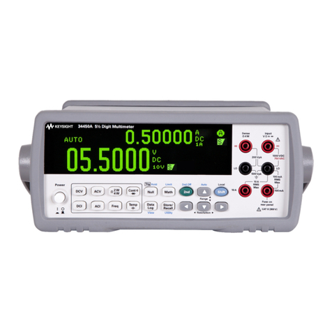
Fluke 8588A User manual

8588A/8558A
Reference Multimeter / 8½ Digit Multimeter
Service Manual
July 2019
© 2019 Fluke Corporation. All rights reserved. Specifications are subject to change without notice.
All product names are trademarks of their respective companies.

LIMITED WARRANTY AND LIMITATION OF LIABILITY
Each Fluke product is warranted to be free from defects in material and workmanship under normal use and
service. The warranty period is one year and begins on the date of shipment. Parts, product repairs, and services
are warranted for 90 days. This warranty extends only to the original buyer or end-user customer of a Fluke
authorized reseller, and does not apply to fuses, disposable batteries, or to any product which, in Fluke's opinion,
has been misused, altered, neglected, contaminated, or damaged by accident or abnormal conditions of operation
or handling. Fluke warrants that software will operate substantially in accordance with its functional specifications
for 90 days and that it has been properly recorded on non-defective media. Fluke does not warrant that software
will be error free or operate without interruption.
Fluke authorized resellers shall extend this warranty on new and unused products to end-user customers only but
have no authority to extend a greater or different warranty on behalf of Fluke. Warranty support is available only if
product is purchased through a Fluke authorized sales outlet or Buyer has paid the applicable international price.
Fluke reserves the right to invoice Buyer for importation costs of repair/replacement parts when product purchased
in one country is submitted for repair in another country.
Fluke's warranty obligation is limited, at Fluke's option, to refund of the purchase price, free of charge repair, or
replacement of a defective product which is returned to a Fluke authorized service center within the warranty
period.
To obtain warranty service, contact your nearest Fluke authorized service center to obtain return authorization
information, then send the product to that service center, with a description of the difficulty, postage and insurance
prepaid (FOB Destination). Fluke assumes no risk for damage in transit. Following warranty repair, the product will
be returned to Buyer, transportation prepaid (FOB Destination). If Fluke determines that failure was caused by
neglect, misuse, contamination, alteration, accident, or abnormal condition of operation or handling, including
overvoltage failures caused by use outside the product’s specified rating, or normal wear and tear of mechanical
components, Fluke will provide an estimate of repair costs and obtain authorization before commencing the work.
Following repair, the product will be returned to the Buyer transportation prepaid and the Buyer will be billed for the
repair and return transportation charges (FOB Shipping Point).
THIS WARRANTY IS BUYER'S SOLE AND EXCLUSIVE REMEDY AND IS IN LIEU OF ALL OTHER
WARRANTIES, EXPRESS OR IMPLIED, INCLUDING BUT NOT LIMITED TO ANY IMPLIED WARRANTY OF
MERCHANTABILITY OR FITNESS FOR A PARTICULAR PURPOSE. FLUKE SHALL NOT BE LIABLE FOR ANY
SPECIAL, INDIRECT, INCIDENTAL, OR CONSEQUENTIAL DAMAGES OR LOSSES, INCLUDING LOSS OF
DATA, ARISING FROM ANY CAUSE OR THEORY.
Since some countries or states do not allow limitation of the term of an implied warranty, or exclusion or limitation
of incidental or consequential damages, the limitations and exclusions of this warranty may not apply to every
buyer. If any provision of this Warranty is held invalid or unenforceable by a court or other decision-maker of
competent jurisdiction, such holding will not affect the validity or enforceability of any other provision.
11/99
Fluke Corporation
P.O. Box 9090
Everett, WA 98206-9090
U.S.A.
Fluke Europe B.V.
P.O. Box 1186
5602 BD Eindhoven
The Netherlands
ООО «Флюк СИАЙЭС»
125167, г. Москва,
Ленинградский проспект дом 37,
корпус 9, подъезд 4, 1 этаж

i
Table of Contents
Title Page
Introduction................................................................................................ 1
Safety Information ..................................................................................... 1
Specifications ............................................................................................ 1
Usage Information ..................................................................................... 1
Contact Fluke Calibration .......................................................................... 2
Calibration Interval and Performance........................................................ 2
Required Equipment ............................................................................. 2
Calibration Adjustment Overview.......................................................... 3
Manual Adjustment .......................................................................... 3
Remote Adjustment .............................................................................. 6
Calibration Verification............................................................................... 6
DC Voltage ........................................................................................... 6
Digitize DC Voltage............................................................................... 11
DC Current............................................................................................ 12
Digitize DC Current............................................................................... 15
AC Voltage............................................................................................ 16
Resistance Normal ............................................................................... 23
Resistance – Tru Ohms ........................................................................ 24
Resistance - Low Current ..................................................................... 25
Resistance - Tru Ohms, Low Current ................................................... 26
Resistance - HV Ohms ......................................................................... 26
Frequency............................................................................................. 27
Capacitance.......................................................................................... 27
Optional Checks ................................................................................... 28
DC Voltage (Rear Input) .................................................................. 28
DC Current (Rear Input)................................................................... 29
AC Voltage (Rear Input)................................................................... 29
AC Current (Rear Input)................................................................... 29
Resistance – HV Ohms (Rear Input)................................................ 29
Maintenance .............................................................................................. 30
Inspection and Cleaning ....................................................................... 30
Clean the Exterior ................................................................................. 30
Clean the Air Inlet ................................................................................. 30
Fuse Replacement................................................................................ 31
Rear-Input Current Fuse....................................................................... 32

8588A/8558A
Service Manual
ii
Self Test ............................................................................................... 32
List of Replaceable Parts .......................................................................... 33
How to Obtain Parts.............................................................................. 33
Remove Hardware Components .......................................................... 39
Handles............................................................................................ 39
Bottom Feet and Tilt Stand Bail ....................................................... 39
Top and Bottom Covers ................................................................... 39
Front-Panel Assembly...................................................................... 40
Rear Panel ....................................................................................... 40
Remove the Transformer Assembly ................................................ 41
Remove A3 Digital PCA Assembly .................................................. 41
Remove the A2 Analogue Assembly ............................................... 41
Remove the A1 Front PCA (Including Keypad and the Display)......42

1
Introduction
The Fluke 8558A 8 1/2 Digit Multimeter and 8588A Reference Multimeter (the Product or Multimeter
unless otherwise specified) are for demanding and precise measurement applications. The Product
functions in both stand-alone and systems applications. 8 1/2 digit resolution provides high
performance and makes the Product well suited for application use in standards labs, calibration labs,
engineering labs, and systems use. The 8588A includes more features and higher performance for the
most demanding metrology applications.
Safety Information
A Warning identifies conditions and procedures that are dangerous to the user. A Caution identifies
conditions and procedures that can cause damage to the Product or the equipment under test.
General Safety Information is located in the printed Safety Information document that ships with the
Product. It can also be found online at www.Flukecal.com. More specific safety information is listed
where applicable.
Specifications
Safety Specifications are located in Safety Specifications section of the Safety Information document.
Complete specifications are at www.flukecal.com. See the 8588A/8558A Product Specifications.
WWarning
If the Product is operated in any way not specified by this manual or other
documentation provided by Fluke, the protection provided by the Product may be
impaired.
Usage Information
Complete Product usage information is located in the 8588A/8558A Operators Manual found online at
www.Flukecal.com.

8588A/8558A
Service Manual
2
Contact Fluke Calibration
To contact Fluke Calibration, call one of the following telephone numbers:
• Technical Support USA: 1-877-355-3225
• Calibration/Repair USA: 1-877-355-3225
• Canada: 1-800-36-FLUKE (1-800-363-5853)
• Europe: +31-40-2675-200
• Japan: +81-3-6714-3114
• Singapore: +65-6799-5566
• China: +86-400-810-3435
• Brazil: +55-11-3759-7600
• Anywhere in the world: +1-425-446-6110
To see product information and download the latest manual supplements, visit Fluke Calibration’s
website at www.flukecal.com.
To register your product, visit http://flukecal.com/register-product.
Calibration Interval and Performance
Fluke Calibration recommends that the Product be calibrated on one of 2-year, 365-day, or 90-day
intervals depending on the requirements of the applications for which the Product is used.
During manufacture, the Product is adjusted and verified with low uncertainties, reflected in the
Absolute Specifications. After recalibration, the user should apply the calibration uncertainties for the
calibration standards and for the process applicable to that calibration by combining those calibration
uncertainties with the Multimeter Relative to Standards specifications.
Required Equipment
Table 1 lists the necessary equipment to adjust Product calibration.
Table 1. Equipment for Calibration Adjustments and Performance Verification
Equipment Name Recommended Models Comment
Multifunction Calibrator Fluke Calibration 5730A
Amplifier Fluke Calibration 5725A
To increase Volt Hz
product and current range
of the Multifunction
Calibrator
Multiproduct calibrator Fluke Calibration 5522A For voltage >1 MHz and
capacitance verification
Transconductance amplifier Fluke Calibration 52120A For currents >11 A,
verification only
10 GΩ Standard Resistor Verification only

Reference Multimeter / 8½ Digit Multimeter
Calibration Interval and Performance
3
Alternate equipment may be used, but users should ensure it provides adequate calibration
uncertainties. Performance of the Product after calibration should be determined by combining the
applicable calibration uncertainties provided by the calibration equipment with the 8508A Relative to
Standards specifications. (Fluke Calibration recommends RSS summation).
Calibration Adjustment Overview
The Product has two sets of stores: Certified and Baseline. Only the Certified stores can be changed
during adjustment. Store is populated at manufacture and would not normally be overwritten. The
Baseline store provides a facility to monitor the long-term performance of the Product independent of
regular adjustment.
Calibration of all functions of the Multimeter is done from the front panel or remotely. No hardware
adjustments are necessary.
Manual Adjustment
The Product guides you though the manual adjustment process. Some early steps in the process are
only required after the Product is repaired.
The adjustments are numbered in groups:
001 After first build or post repair
101 One-time factory characterizations
201 Voltage
301 Current
401 Resistance
501 Capacitance (not applicable to 8558A)
601 Frequency
701 Zero
The full list of adjustment points and required inputs is in Table 2. Routine adjustment starts at Step
201: ADC Reference Characterize.
Equipment Name Recommended Models Comment
1 GΩ Standard Resistor Fluke Calibration 8508A-7000K
1 GΩ Standard, Low
thermal emf leads, two 4-
wire shorting PCB
100 MΩ Standard Resistor
1 Ω Standard Resistor Fluke 742-1
1 nF Standard Capacitor
8588A adjustment only
(not required for 8558A
adjustment)
10 MHz Reference Off-air standard
4-wire short PCB
Table 1. Equipment for Calibration Adjustments and Performance Verification (cont.)

8588A/8558A
Service Manual
4
Not all function range combinations need to be adjusted. To improve efficiency, some adjustments are
derived from other adjustments, so it is important to follow the adjustment process in the given
sequence. Individual points can be adjusted in isolation later if required.
To enter calibration adjustment mode:
1. Push .
2. Push (Calibration Adjustment).
3. To enter the adjustment mode, push (Enter Passcode).
4. Enter the passcode (123456 is the default).
5. Make sure that Set Active Stores indicates Certified.
6. Push to highlight: Certified Stores Adjustment and push .
The screen for each adjustment step has two to four data fields, see Figure 1.
7. Use Table 2 to apply the input values.
Figure 1. Calibration Adjustment Screen
Regarding the Calibration Adjustment screen (see Figure 1):
•Step number and a description is always present.
•An Input value is always shown. The Input may be a discrete value or N/A (not applicable)
if no input is required (terminals open circuit).
• If Target shows, it is an editable value to allow non-nominal values to be entered, for
example exact resistance reference values.
• Some adjust steps show a measured value. For some steps, the value may not be
obviously related to the step description.
8. When the input requirements (if any) have been applied, push (Adjust) to make the
adjustment.
•Adjust operation: in progress… shows as the adjustment takes place.
•Adjust operation: Done indicates the adjustment is complete.
9. Push (Next Step) to move to the next step in the process.

Reference Multimeter / 8½ Digit Multimeter
Calibration Interval and Performance
5
10. Continue through the adjustment process until all steps are complete.
The last adjustment for 8558A is: Step 703: Current Zero. The last step for 8588A is Step 704:
Capacitance zero.
Table 2. Table Points
Step Description Input
201 ADC Reference Characterize N/A
202 10 mV Offset 0 mV
203 10 mV Gain +10 mV
204 100 mV Offset 0 mV
205 100 mV Gain +100 mV
206 1 V Offset 0 V
207 1 V Gain +1 V
208 10 V Offset 0 V
209 10 V Gain +10 V
210 100 V Offset 0 V
211 100 V Gain +100 V
212 1 kV Offset 0 V
213 1 kV Gain +1 kV
214 ACV 1 MΩ HF 1 kHz Ref 100 V 1 kHz
215 ACV 1 MΩ HF 60 kHz 100 V 60 kHz
301 100 μA Offset 0 μA
302 100 μA Gain +100 μA
303 1 mA Offset 0 mA
304 1 mA Gain +1 mA
305 10 mA Offset 0 mA
306 10 mA Gain +10 mA
307 100 mA Offset 0 mA
308 100 mA Gain +100 mA
309 1 A Offset 0 A
310 1 A Gain +1 A
311 [1] 10 A Offset 0 A
312 [1] 10 A Gain +10 A

8588A/8558A
Service Manual
6
Remote Adjustment
Refer to Manual Adjustment for the process steps. Remote commands are in the Calibration
subsystem section of the 8588A/8558A Programmers Guide found online at www.Flukecal.com.
Calibration Verification
The permissible errors shown are the 99 % confidence, 1-year, absolute errors. These error values
include Fluke Calibration calibration uncertainty. Adjust the permissible error values to reflect the actual
measurement uncertainty if they are different from the listed values.
DC Voltage
Configuration: Z in Auto, Internal Guard, Front Input, Aperture = Auto, Resolution 7.5 Digits, Suggested
Reference: 5730A
Step Description Input
401 Ohms 4W Offset 0 Ω 4W
402 10 Ω Gain 10 Ω 4W
403 100 Ω Gain 100 Ω 4W
404 1 kΩ Gain 1 kΩ 4W
405 10 kΩ Gain 10 kΩ 4W
406 100 kΩ Gain 100 kΩ 4W
407 1 MΩ Gain 1 MΩ 4W
408 10 MΩ Gain 10 MΩ 4W
409 100 MΩ Gain 100 MΩ 4W
410 1 GΩ Gain 1 GΩ 4W
411 1 Ω Zero 0 Ω 4W
412 1 Ω Gain 1 Ω 4W
501 [1] Capacitance Zero N/A
502 [1] 1 nF Gain 1 nF
601 Frequency 10 MHz (Rear BNC)
701 Voltage Zero N/A
702 Resistance Zero 4W 4W Short Circuit
703 Current Zero N/A
704 [1] Capacitance Zero N/A
[1] Points are unavailable in 8558A.
Table 2. Table Points (cont.)

Reference Multimeter / 8½ Digit Multimeter
Calibration Verification
7
Configuration: Z in Auto, 7.5 Digits, Internal Guard, Front Input, Aperture = Auto
Range Reference Value Permissible Error (±)Fluke Calibration
Uncertainty (±)
8588A 8558A
100 mV 0.000 00 mV 0.000 27 mV 0.000 27 mV 0.000 048 mV
100 mV 100.000 00 mV 0.000 92 mV 0.001 02 mV 0.000 320 mV
100 mV 200.000 00 mV 0.001 57 mV 0.001 78 mV 0.000 640 mV
100 mV 0.000 00 mV 0.000 27 mV 0.000 27 mV 0.000 048 mV
100 mV -100.000 00 mV 0.00092 mV 0.001 03 mV 0.000 320 mV
100 mV -200.000 00 mV 0.001 57 mV 0.001 79 mV 0.000 640 mV
1 V 0.000 000 0 V 0.000 000 4 V 0.000 000 5 V 0.000 000 16 V
1 V 1.000 000 0 V 0.000 004 0 V 0.000 005 8 V 0.000 000 86 V
1 V 2.000 000 0 V 0.000 007 6V 0.000 011 1 V 0.000 001 70 V
1 V 0.000 000 0 V 0.000 000 4 V 0.000 000 5 V 0.000 000 16 V
1 V -1.000 000 0 V 0.000 004 0 V 0.000 005 8 V 0.000 000 86 V
1 V -2.000 000 0 V 0.000 007 6 V 0.000 011 1 V 0.000 001 70 V
10 V 0.000 000 V 0.000 001 V 0.000 001 V 0.000 000 30 V
10 V 0.100 000 V 0.000 001 V 0.000 002 V 0.000 000 54 V
10 V 1.000 000 V 0.000 005 V 0.000 007 V 0.000 001 30 V
10 V 5.000 000 V 0.000 019 V 0.000 028 V 0.000 003 20 V
10 V 10.000 000 V 0.000 037 V 0.000 054 V 0.000 006 40 V
10 V 15.000 000 V 0.000 055 V 0.000 081 V 0.000 009 60 V
10 V 20.000 000 V 0.000 073 V 0.000 107 V 0.000 013 00 V
10 V 0.000 000 V 0.000 001 1 V 0.000 001 V 0.000 000 30 V
10 V -0.100 000 V 0.000 001 5 V 0.000 002 V 0.000 000 54 V
10 V -1.000 000 V 0.000 005 V 0.000 007 V 0.000 001 30 V
10 V -5.000 000 V 0.000 019 V 0.000 028 V 0.000 003 20 V
10 V -10.000 000 V 0.000 037 V 0.000 054 V 0.000 006 40 V
10 V -15.000 000 V 0.000 055 V 0.000 081 V 0.000 009 60 V
10 V -20.000 000 V 0.000 073 V 0.000 107 V 0.000 013 00 V

8588A/8558A
Service Manual
8
Configuration: Z in 1 MΩ, 7.5 Digits, Internal Guard, Front Input, Aperture = Auto.
Range Reference Value Permissible Error (±)Fluke Calibration
Uncertainty (±)
8588A 8558A
100 V 0.000 00 V 0.000 04 V 0.000 05 V 0.000 026 V
100 V 100.000 00 V 0.000 57 V 0.000 83 V 0.000 100 V
100 V 200.000 00 V 0.001 10 V 0.001 61 V 0.000 200 V
100 V 0.000 00 V 0.000 04 V 0.000 05 V 0.000 026 V
100 V -100.000 00 V 0.000 57 V 0.000 83 V 0.000 100 V
100 V -200.000 00 V 0.001 10 V 0.001 61 V 0.000 200 V
1000 V 0.000 0 V 0.000 7 V 0.001 7 V 0.000 30 V
1000 V 500.000 0 V 0.003 4 V 0.005 7 V 0.000 80 V
1000 V 1000.000 0 V 0.006 2 V 0.009 7 V 0.001 60 V
1000 V -500.000 0 V 0.003 4 V 0.005 7 V 0.000 80 V
1000 V -1000.000 0 V 0.006 2 V 0.009 7 V 0.001 60 V
Range Reference Value Permissible Error (±)Fluke Calibration
Uncertainty (±)
8588A 8558A
100 V 0.000 00 V 0.000 66 V 0.000 66 V 0.000 23 V
100 V 100.000 00 V 0.001 86 V 0.001 96V 0.000 10 V
100 V 200.000 00 V 0.003 06 V 0.003 26 V 0.000 20 V
100 V 0.000 00 V 0.000 66 V 0.000 66 V 0.000 03 V
100 V -100.000 00 V -0.001 86 V 0.001 96V 0.000 10 V
100 V -200.000 00 V -0.003 06 V 0.003 26 V 0.000 20 V
1000 V 0.000 0 V 0.032 05 V 0.032 1 V 0.000 30 V
1000 V 500.000 0 V 0.038 05 V 0.038 6 V 0.000 80 V
1000 V 1000.000 0 V 0.044 05 V 0.045 1 V 0.001 60 V
1000 V -500.000 0 V 0.038 05 V 0.038 6 V 0.000 80 V
1000 V -1000.000 0 V 0.044 05 V 0.045 1 V 0.001 60 V

Reference Multimeter / 8½ Digit Multimeter
Calibration Verification
9
Configuration: Z in Auto, 7.5 Digits, Internal Guard, Front Input, Aperture = 99 μs.
Range Reference Value Permissible Error (±)Fluke Calibration
Uncertainty (±)
8588A 8558A
100 mV 0.000 00 mV 0.001 90 mV 0.001 90 mV 0.000 70 mV
100 mV 100.000 00 mV 0.007 70 mV 0.007 70 mV 0.000 74 mV
100 mV 200 000 00 mV 0.013 50 mV 0.013 50 mV 0.001 50 mV
100 mV 0.000 00 mV 0.001 90 mV 0.001 90 mV 0.000 70 mV
100 mV -100.000 00 mV 0.007 70 mV 0.007 70 mV 0.000 74 mV
100 mV -200 000 00 mV 0.013 50 mV 0.013 50 mV 0.001 50 mV
1 V 0.000 000 0 V 0.000 019 0 V 0.000 019 0 V 0.000 002 3 V
1 V 0.010 000 0 V 0.000 019 6 V 0.000 019 6 V 0.000 003 0 V
1 V 0.100 000 0 V 0.000 024 8 V 0.000 024 8 V 0.000 003 7 V
1 V 1.000 000 0 V 0.000 077 0 V 0.000 077 0 V 0.000 007 0 V
1 V 1.5000 000 0 V 0.000 106 0 V 0.000 106 0 V 0.000 007 1 V
1 V 2.0000 000 0 V 0.000 135 0 V 0.000 135 0 V 0.000 009 5 V
1 V 0.000 000 0 V 0.000 019 0 V 0.000 019 0 V 0.000 002 3 V
1 V -0.010 000 0 V 0.000 019 6 V 0.000 019 6 V 0.000 003 0 V
1 V -0.100 000 0 V 0.000 024 8 V 0.000 024 8 V 0.000 003 7 V
1 V -1.000 000 0 V 0.000 077 0 V 0.000 077 0 V 0.000 007 0 V
1 V -1.5000 000 0 V 0.000 106 0 V 0.000 106 0 V 0.000 007 1 V
1 V -2.0000 000 0 V 0.000 135 0 V 0.000 135 0 V 0.000 009 5 V
10 V 0.000 000 V 0.000 190 V 0.000 190 V 0.000 023 V
10 V 10.000 000 V 0.000 770 V 0.000 770 V 0.000 070 V
10 V 20.000 000 V 0.001 350 V 0.001 350 V 0.000 140 V
10 V 0.000 000 V 0.000 190 V 0.000 190 V 0.000 023 V
10 V -10.000 000 V 0.000 770 V 0.000 770 V 0.000 070 V
10 V -20.000 000 V 0.001 350 V 0.001 350 V 0.000 140 V
100 V 0.000 00 V 0.001 90 V 0.001 90 V 0.000 23 V
100 V 100.000 00 V 0.007 70 V 0.007 70 V 0.000 70 V
100 V 200 000 00 V 0.013 50 V 0.013 50 V 0.001 40 V
100 V 1.000 000 V 0.001 90 V 0.001 90 V 0.000 23 V
100 V -100.000 00 V 0.007 70 V 0.007 70 V 0.000 70 V
100 V -200 000 00 V 0.013 50 V 0.013 50 V 0.001 40 V

8588A/8558A
Service Manual
10
Configuration: Z in 1 MΩ, 7.5 Digits, Internal Guard, Front Input, Aperture = 99 µs.
Range Reference Value Permissible Error (±)Fluke Calibration
Uncertainty (±)
8588A 8558A
1000 V 0.000 0 V 0.019 0 V 0.019 0 V 0.002 4 V
1000 V 500.000 0 V 0.048 0 V 0.048 0 V 0.003 5 V
1000 V 1000.000 0 V 0.077 0 V 0.077 0 V 0.007 1 V
1000 V -500.000 0 V 0.048 0 V 0.048 0 V 0.003 5 V
1000 V -1000.000 0 V 0.077 0 V 0.077 0 V 0.007 1 V
Range Reference Value Permissible Error (±)Fluke Calibration
Uncertainty (±)
8588A 8558A
100 V 0.000 00 V 0.001 90 V 0.001 90 V 0.000 23 V
100 V 100.000 00 V 0.007 70 V 0.007 70 V 0.000 70 V
100 V 200.000 00 V 0.013 50 V 0.013 50 V 0.001 40 V
100 V 0.000 00 V 0.001 90 V 0.001 90 V 0.000 23 V
100 V -100.000 00 V 0.007 70 V 0.007 70 V 0.000 70 V
100 V -200.000 00 V 0.013 50 V 0.013 50 V 0.001 40 V
1000 V 0.000 0 V 0.019 0 V 0.019 0 V 0.002 40 V
1000 V 500.000 0 V 0.048 0 V 0.048 0 V 0.003 50 V
1000 V 1000.000 0 V 0.077 0 V 0.077 0 V 0.007 10 V
1000 V -500.000 0 V 0.048 0 V 0.048 0 V 0.003 50 V
1000 V -1000.000 0 V 0.077 0 V 0.077 0 V 0.007 10 V

Reference Multimeter / 8½ Digit Multimeter
Calibration Verification
11
Digitize DC Voltage
Configuration: Z in DC Auto, Aperture = 200 ns, Trigger count 101010, Low pass filter Off.
Configuration: Z in DC Auto, Aperture = 200 ns, Trigger count 101010, Low pass filter 100 kHz.
Configuration: Z in DC Auto, Aperture = 200 ns, Trigger count 101010, Low pass filter 3 MHz.
Range Reference Value Permissible Error (±)Fluke Calibration
Uncertainty (±)
8588A 8558A
1 V 0.000 000 0V 0.000 054 0 V 0.000 054 0 V 0.000 006 0 V
1 V 1.000 000 0V 0.000 157 0V 0.000 157 0V 0.000 006 1 V
1 V -1.000 000 0V 0.000 157 0V 0.000 157 0V 0.000 006 1 V
Range Reference Value Permissible Error (±)Fluke Calibration
Uncertainty (±)
8588A 8558A
1 V 0.000 000 0V 0.000 019 0 V 0.000 019 0 V 0.000 006 0 V
1 V 1.000 000 0V 0.000 082 0V 0.000 082 0V 0.000 006 1 V
1 V -1.000 000 0V 0.000 082 0V 0.000 082 0V 0.000 006 1 V
Range Reference Value Permissible Error (±)Fluke Calibration
Uncertainty (±)
8588A 8558A
1 V 0.000 000 0V 0.000 019 0 V 0.000 019 0 V 0.000 006 0 V
1 V 1.000 000 0V 0.000 082 0V 0.000 082 0V 0.000 006 1 V
1 V -1.000 000 0V 0.000 082 0V 0.000 082 0V 0.000 006 1 V

8588A/8558A
Service Manual
12
DC Current
Configuration: 7.5 Digits, Internal Guard, Front Input, Filter Off, Aperture = Auto.
Suggested Reference: 5730A
Range Reference Value Permissible Error (±)Fluke Calibration
Uncertainty (±)
8588A 8558A
10 μA 0.000 000 μA 0.000 520 μA 0.000 520 μA 0.000 120 μA
10 μA 10.000 000 μA 0.000 830 μA 0.000 890 μA 0.000 120 μA
10 μA 20.000 000 μA 0.001 140 μA 0.001 260 μA 0.000 240 μA
10 μA 0.000 000 μA 0.000 520 μA 0.000 520 μA 0.000 120 μA
10 μA -10.000 000 μA 0.000 830 μA 0.000 890 μA 0.000 120 μA
10 μA -20.000 000 μA 0.001 140 μA 0.001 260 μA 0.000 240 μA
100 μA 0.000 00 μA 0.000 05 μA 0.000 60 μA 0.000 12 μA
100 μA 100.000 00 μA 0.001 60 μA 0.001 90 μA 0.000 45 μA
100 μA 200.000 00 μA 0.002 70 μA 0.003 20 μA 0.000 90 μA
100 μA 0.000 00 μA 0.000 05 μA 0.000 60 μA 0.000 12 μA
100 μA -100.000 00 μA 0.001 60 μA 0.001 90 μA 0.000 45 μA
100 μA -200.000 00 μA 0.002 70 μA 0.003 20 μA 0.000 90 μA
1 mA 0.000 000 0 mA 0.000 005 0 mA 0.000 010 0 mA 0.000 001 5 mA
1 mA 1.000 000 0 mA 0.000 015 0 mA 0.000 020 0 mA 0.000 003 9 mA
1 mA 2.000 000 0 mA 0.000 025 0 mA 0.000 030 0 mA 0.000 007 8 mA
1 mA 0.000 000 0 mA 0.000 005 0 mA 0.000 010 0 mA 0.000 001 5 mA
1 mA -1.000 000 0 mA 0.000 015 0 mA 0.000 020 0 mA 0.000 003 9 mA
1 mA -2.000 000 0 mA 0.000 025 0 mA 0.000 030 0 mA 0.000 007 8 mA
10 mA 0.000 000 mA 0.000 050 mA 0.000 060 mA 0.000 014 mA
10 mA 10.000 000 mA 0.000 160 mA 0.000 200 mA 0.000 039 mA
10 mA 20.000 000 mA 0.000 270 mA 0.000 340 mA 0.000 078 mA
10 mA 0.000 000 mA 0.000 050 mA 0.000 060 mA 0.000 014 mA
10 mA -10.000 000 mA 0.000 160 mA 0.000 200 mA 0.000 039 mA
10 mA -20.000 000 mA 0.000 270 mA 0.000 340 mA 0.000 078 mA
100 mA 0.000 00 mA 0.001 30 mA 0.001 90 mA 0.000 26 mA
100 mA 100.000 00 mA 0.005 60 mA 0.006 40 mA 0.000 58 mA
100 mA 200.000 00 mA 0.009 90 mA 0.010 90 mA 0.001 20 mA

Reference Multimeter / 8½ Digit Multimeter
Calibration Verification
13
Configuration: 7.5 Digits, Internal Guard, Front Input, Filter Off, Aperture = 99 μs.
Range Reference Value Permissible Error (±)Fluke Calibration
Uncertainty (±)
8588A 8558A
100 mA 0.000 00 mA 0.001 30 mA 0.001 90 mA 0.000 26 mA
100 mA -100.000 00 mA 0.005 60 mA 0.006 40 mA 0.000 58 mA
100 mA -200.000 00 mA 0.009 90 mA 0.010 90 mA 0.001 20 mA
1 A 0.000 000 0 A 0.000 129 0 A 0.000 190 0 A 0.000 002 6 A
1 A 1.000 000 0 A 0.000 259 0 A 0.000 350 0 A 0.000 025 0 A
1 A 2.000 000 0 A 0.000 389 0 A 0.000 500 0 A 0.000 049 0 A
1 A 0.000 000 0 A 0.000 129 0 A 0.000 190 0 A 0.000 002 6 A
1 A -1.000 000 0 A 0.000 259 0 A 0.000 350 0 A 0.000 025 0 A
1 A -2.000 000 0 A 0.000 389 0 A 0.000 500 0 A 0.000 049 0 A
30 A 0.000 000 A 0.000 520 A n/a 0.000 071 A
30 A 10.000 000 A 0.003 540 A n/a 0.000 420 A
30 A 30.000 000 A 0.024 660 A n/a 0.000 760 A
30 A 0.000 000 A 0.000 520 A n/a 0.000 071 A
30 A -10.000 000 A 0.003 540 A n/a 0.000 420 A
30 A -30.000 000 A 0.024 660 A n/a 0.000 760 A
Range Reference Value Permissible Error (±)Fluke Calibration
Uncertainty (±)
8588A 8558A
10 μA 0.000 000 μA 0.001 03 μA 0.001 03 μA 0.000 140 μA
10 μA 10.000 000 μA 0.001 63 μA 0.001 63 μA 0.000 240 μA
10 μA 20.000 000 μA 0.002 23 μA 0.002 23 μA 0.000 480 μA
10 μA 0.000 000 μA 0.001 03 μA 0.001 03 μA 0.000 140 μA
10 μA -10.000 000 μA 0.001 63 μA 0.001 63 μA 0.000 240 μA
10 μA -20.000 000 μA 0.002 23 μA 0.002 23 μA 0.000 480 μA
100 μA 0.000 00 μA 0.009 00 μA 0.009 00 μA 0.000 47 μA
100 μA 100.000 00 μA 0.014 70 μA 0.014 70 μA 0.000 79 μA
100 μA 200.000 00 μA 0.002 40 μA 0.002 40 μA 0.001 60 μA
100 μA 0.000 00 μA 0.009 00 μA 0.009 00 μA 0.000 47 μA
100 μA -100.000 00 μA 0.014 70 μA 0.014 70 μA 0.000 79 μA
100 μA -200.000 00 μA 0.002 40 μA 0.002 40 μA 0.001 60 μA

8588A/8558A
Service Manual
14
Range Reference Value Permissible Error (±)Fluke Calibration
Uncertainty (±)
8588A 8558A
1 mA 0.000 000 0 mA 0.000 090 0 mA 0.000 090 0 mA 0.000 002 6 mA
1 mA 1.000 000 0 mA 0.000 147 0 mA 0.000 147 0 mA 0.000 005 8 mA
1 mA 2.000 000 0 mA 0.000 204 0 mA 0.000 204 0 mA 0.000 012 0 mA
1 mA 0.000 000 0 mA 0.000 090 0 mA 0.000 090 0 mA 0.000 002 6 mA
1 mA -1.000 000 0 mA 0.000 147 0 mA 0.000 147 0 mA 0.000 005 8 mA
1 mA -2.000 000 0 mA 0.000 204 0 mA 0.000 204 0 mA 0.000 012 0 mA
10 mA 0.000 000 mA 0.000 900 mA 0.000 900 mA 0.000 041 mA
10 mA 10.000 000 mA 0.001 470 mA 0.001 470 mA 0.000 077 mA
10 mA 20.000 000 mA 0.002 040 mA 0.002 040 mA 0.000 150 mA
10 mA 0.000 000 mA 0.000 900 mA 0.000 900 mA 0.000 041 mA
10 mA -10.000 000 mA 0.001 470 mA 0.001 470 mA 0.000 077 mA
10 mA -20.000 000 mA 0.002 040 mA 0.002 040 mA 0.000 150 mA
100 mA 0.000 00 mA 0.009 00 mA 0.009 00 mA 0.000 48 mA
100 mA 100.000 00 mA 0.014 70 mA 0.014 70 mA 0.001 20 mA
100 mA 200.000 00 mA 0.020 40 mA 0.020 40 mA 0.002 40 mA
100 mA 0.000 00 mA 0.009 00 mA 0.009 00 mA 0.000 48 mA
100 mA -100.000 00 mA 0.014 70 mA 0.014 70 mA 0.001 20 mA
100 mA -200.000 00 mA 0.020 40 mA 0.020 40 mA 0.002 40 mA
1 A 0.000 000 0 A 0.000 16 A 0.000 16 A 0.000 012 0 A
1 A 1.000 000 0 A 0.000 30 A 0.000 30 A 0.000 033 0 A
1 A 2.000 000 0 A 0.000 45 A 0.000 45 A 0.000 067 0 A
1 A 0.000 000 0 A 0.000 16 A 0.000 16 A 0.000 012 0 A
1 A -1.000 000 0 A 0.000 30 A 0.000 30 A 0.000 033 0 A
1 A -2.000 000 0 A 0.000 45 A 0.000 45 A 0.000 067 0 A
10 A 0.000 000 A 0.002 06 A n/a 0.000 19 A
10 A 10.000 000 A 0.004 43 A n/a 0.000 40 A
10 A 0.000 000 A 0.002 06 A n/a 0.000 19 A
10 A -10.000 000 A 0.004 43 A n/a 0.000 40 A

Reference Multimeter / 8½ Digit Multimeter
Calibration Verification
15
Digitize DC Current
Configuration: Aperture = 200 ns, Trigger count 101010, Low pass filter Off.
Configuration: Aperture = 200 ns, Trigger count 101010, Low pass filter 100 kHz.
Configuration: Aperture = 200 ns, Trigger count 101010, Low pass filter 3 MHz.
Range Reference Value Permissible Error (±)Fluke Calibration
Uncertainty (±)
8588A 8558A
10 mA 0.000 000 00mA 0.001 600 mA 0.001 600 mA 0.000 280 mA
10 mA 10.000 000 mA 0.002 620 mA 0.002 620 mA 0.000 280 mA
10 mA -0.000 000 mA 0.001 600 mA 0.001 600 mA 0.000 280 mA
10 mA -10.000 000 mA 0.002 620 mA 0.002 620 mA 0.000 280 mA
Range Reference Value Permissible Error (±)Fluke Calibration
Uncertainty (±)
8588A 8558A
10 mA 0.000 000 0 mA 0.000 900 mA 0.000 900 mA 0.000 230 mA
10 mA 1.000 000 0 mA 0.001 520 mA 0.001 520 mA 0.000 240 mA
10 mA -0.000 000 0 mA 0.000 900 mA 0.000 900 mA 0.000 230 mA
10 mA -1.000 000 0 mA 0.001 520 mA 0.001 520 mA 0.000 240 mA
Range Reference Value Permissible Error (±)Fluke Calibration
Uncertainty (±)
8588A 8558A
10 mA 0.000 000 0 mA 0.000 900 mA 0.000 900 mA 0.000 230 mA
10 mA 1.000 000 0 mA 0.001 520 mA 0.001 520 mA 0.000 240 mA
10 mA 0.000 000 0 mA 0.000 900 mA 0.000 900 mA 0.000 230 mA
10 mA -1.000 000 0 mA 0.001 520 mA 0.001 520 mA 0.000 240 mA

8588A/8558A
Service Manual
16
AC Voltage
Configuration: Input: Front, Ext Guard: ON, Resolution: 6 digits, Measure Setup: DC 1 MΩ, Frequency
Path Bandwidth Limit: OFF,
Band: Wideband (For frequencies >1 MHz: Extended High Frequency).
Note
Suggested Reference: 5730A
Range Frequency RMS
Filter
Reference
Value
Permissible Error (±)Fluke
Calibration
Uncertainty (±)
8588A 8558A
10 mV DC 10 Hz 0.000 00 mV 0.021 92 mV 0.023 08 mV 0.000 90 mV
10 mV DC 10 Hz 10.000 00 mV 0.025 65 mV 0.030 93 mV 0.000 90 mV
10 mV DC 10 Hz -10.000 00 mV 0.025 65 mV 0.030 93 mV 0.000 90 mV
10 mV 10 Hz 1 Hz 10.000 00 mV 0.004 65 mV 0.009 93 mV 0.001 40 mV
10 mV 40 Hz 10 Hz 10.000 00 mV 0.004 65 mV 0.009 93 mV 0.001 30 mV
10 mV 105 Hz 10 Hz 10.000 00 mV 0.004 65 mV 0.009 93 mV 0.001 30 mV
10 mV 1 kHz 10 Hz 10.000 00 mV 0.004 65 mV 0.009 93 mV 0.001 30 mV
10 mV (AC) 1 kHz 10 Hz 10.000 00 mV 0.004 65 mV 0.009 93 mV 0.001 30 mV
10 mV 2 kHz 10 Hz 10.000 00 mV 0.004 65 mV 0.009 93 mV 0.001 30 mV
10 mV 10 kHz 10 Hz 10.000 00 mV 0.005 81 mV 0.008 03 mV 0.001 30 mV
10 mV 30 kHz 10 Hz 10.000 00 mV 0.005 81 mV 0.008 16 mV 0.001 60 mV
10 mV 60 kHz 10 Hz 10.000 00 mV 0.040 00 mV 0.056 60 mV 0.001 60 mV
10 mV 100 kHz 10 Hz 10.000 00 mV 0.040 00 mV 0.056 60 mV 0.001 60 mV
10 mV 300 kHz 10 Hz 10.000 00 mV 0.134 00 mV 0.214 70 mV 0.001 90 mV
10 mV 1 MHz 10 Hz 10.000 00 mV 0.263 00 mV 0.330 70 mV 0.007 20 mV
100 mV DC 10 Hz 0.000 0 mV 0.025 7 mV 0.026 3 mV 0.000 0 mV
100 mV DC 10 Hz 100.000 0 mV 0.039 4 mV 0.042 9 mV 0.001 0 mV
100 mV 10 Hz 10 Hz 100.000 0 mV 0.009 4 mV 0.018 1 mV 0.003 2 mV
100 mV 40 Hz 10 Hz 100.000 0 mV 0.009 4 mV 0.018 1 mV 0.002 5 mV
100 mV 105 Hz 10 Hz 100.000 0 mV 0.009 5 mV 0.018 1 mV 0.002 6 mV
100 mV 1 kHz 10 Hz 10.000 0 mV 0.001 5 mV 0.003 0 mV 0.001 2 mV
100 mV 1 kHz 10 Hz 100.000 0 mV 0.009 5 mV 0.003 0 mV 0.002 4 mV
100 mV (AC) 1 kHz 10 Hz 100.000 0 mV 0.009 5 mV 0.018 1 mV 0.002 4 mV
100 mV 1 kHz 10 Hz 120.000 0 mV 0.011 2 mV 0.021 5 mV 0.002 9 mV
Other manuals for 8588A
1
This manual suits for next models
1
Table of contents
Other Fluke Multimeter manuals

Fluke
Fluke 365 Use and care manual

Fluke
Fluke 83 User manual

Fluke
Fluke 8022A User manual

Fluke
Fluke 8021B User manual

Fluke
Fluke 113 User manual

Fluke
Fluke 287 Installation and operating instructions

Fluke
Fluke 1550B Instruction manual

Fluke
Fluke 8840A User manual

Fluke
Fluke 8024B User manual

Fluke
Fluke 8845A User manual

Fluke
Fluke 279 FC Use and care manual

Fluke
Fluke 175 Use and care manual

Fluke
Fluke 8842A User manual

Fluke
Fluke 8808A Configuration guide

Fluke
Fluke 1587 Use and care manual

Fluke
Fluke 8860A User manual

Fluke
Fluke CNX 3000 User manual

Fluke
Fluke 112 User manual

Fluke
Fluke 27-II Use and care manual

Fluke
Fluke 80 Series V User manual