Fluke 15B Use and care manual

April 2016
© 2016 Fluke Corporation. All rights reserved. Specifications are subject to change without notice.
All product names are trademarks of their respective companies.
15B+/17B+/18B+
Digital Multimeter
Calibration Manual


i
Table of Contents
Title Page
Introduction............................................................................................ 1
How to Contact Fluke............................................................................ 1
Safety Information ................................................................................. 2
General Specifications .......................................................................... 5
Accuracy Specifications ........................................................................ 6
AC and DC Voltage ........................................................................... 6
AC and DC Current ........................................................................... 6
Diode Test, Temperature, Resistance, Capacitance, Frequency,
and Duty Cycle .................................................................................. 7
LED Test and Continuity Threshold................................................... 8
Input Characteristics.......................................................................... 8
Disassembly.......................................................................................... 10
Performance Tests ................................................................................ 10
Performance Tests for the 15B+ and 17B+....................................... 11
Performance Test for 18B+ ............................................................... 13
Calibration Procedures.......................................................................... 15
Calibration for 15B+ and 17B+ .......................................................... 16
Calibration for 18B+........................................................................... 18

15B+/17B+/18B+
Calibration Manual
ii

iii

1
Introduction
The Fluke 15B+/17B+/18B+ Digital Multimeters (the Product or UUT) are
4000-count instruments. The Product is battery powered with a digital display.
Except where noted, the descriptions and instructions in this manual apply to all
models.
Unless otherwise identified, all illustrations show the 17B+.
See the Users Manual for user-replaceable parts.
How to Contact Fluke
To contact Fluke, call one of the following telephone numbers:
• Technical Support USA: 1-800-44-FLUKE (1-800-443-5853)
• Calibration/Repair USA: 1-888-99-FLUKE (1-888-993-5853)
• Canada: 1-800-36-FLUKE (1-800-363-5853)
• Europe: +31 402-675-200
• Japan: +81-03-6714-3114
• Singapore: +65-6799-5566
• Mainland China: +86-400-810-3435
• Anywhere in the world: +1-425-446-5500
Or, visit Fluke's website at www.fluke.com
To register your product, visit http://register.fluke.com.
To see, print, or download the latest manual supplement, visit
http://us.fluke.com/usen/support/manuals.

15B+/17B+/18B+
Calibration Manual
2
Safety Information
A Warning identifies conditions and procedures that are dangerous to the user.
A Caution identifies conditions and procedures that could cause damage to the
Product or the equipment under test.
Table 1 is a list of the international electrical symbols used on the Product and in
this manual.
Review the safety information and comply with the safe working practices.
XW Warning
To prevent possible electrical shock, fire, or personal injury:
• Carefully read all instructions.
• Read all safety information before you use the Product.
• Use the Product only as specified, or the protection
supplied by the Product can be compromised.
• Do not use the Product around explosive gas, vapor, or in
damp or wet environments.
• Examine the case before you use the Product. Look for
cracks or missing plastic. Carefully look at the insulation
around the terminals.
• Do not use the Product if it is damaged.
• Do not use the Product if it operates incorrectly.
• Comply with local and national safety codes. Use personal
protective equipment (approved rubber gloves, face
protection, and flame-resistant clothes) to prevent shock
and arc blast injury where hazardous live conductors are
exposed.
• Use only correct measurement category (CAT), voltage,
and amperage rated probes, test leads, and adapters for
the measurement.
• Do not use test probes in CAT III environments without the
protective cap installed. The protective cap decreases the
exposed probe metal to <4 mm. This decreases the
possibility of arc flash from short circuits.
• Measure a known voltage first to make sure that the
Product operates correctly.
• Limit operation to the specified measurement category,
voltage, or amperage ratings.
• Do not apply more than the rated voltage, between the
terminals or between each terminal and earth ground.
• Do not touch voltages > 30 V ac rms, 42 V ac peak, or
60 V dc.
• Do not use test leads if they are damaged. Examine the test
leads for damaged insulation and measure a known
voltage.

Digital Multimeter
Safety Information
3
• Keep fingers behind the finger guards on the probes.
• Remove all probes, test leads, and accessories before the
battery door is opened.
• Do not exceed the Measurement Category (CAT) rating of
the lowest rated individual component of a Product, probe,
or accessory.
• Remove the batteries if the Product is not used for an
extended period of time, or if stored in temperatures above
50 °C. If the batteries are not removed, battery leakage can
damage the Product.
• Replace the batteries when the low battery indicator ()
shows to prevent incorrect measurements.
• Use the correct terminals, function, and range for
measurements.
• Disconnect all test leads from any hazardous voltage
before switching to the LED TEST function. Refer to the
LED TEST section for proper measurement technique and
interpretation of results (for 18B+ only).
• The battery door must be closed and locked during
verification.
• Do not operate the Product with covers removed or the
case open. Hazardous voltage exposure is possible.
• Do not apply hazardous voltages during the calibration
procedure.

15B+/17B+/18B+
Calibration Manual
4
Table 1. Symbols
Symbol Description Symbol Description
AC (Alternating Current) Earth Ground
DC (Direct Current) Fuse
Diode Capacitance
XWARNING. HAZARDOUS
VOLTAGE. Risk of electrical shock. Battery
WWARNING. RISK OF DANGER. Consult user documentation.
Measurement Category II is
applicable to test and measuring
circuits connected directly to
utilization points (socket outlets and
similar points) of the low-voltage
MAINS installation.
Measurement Category IV is
applicable to test and measuring
circuits connected at the source of
the building’s low-voltage MAINS
installation.
Measurement Category III is
applicable to test and measuring
circuits connected to the distribution
part of the building’s low-voltage
MAINS installation.
)Conforms to relevant North
American Safety Standards.
PConforms to European Union
directives. Conforms to relevant Australian
Standards.
ÃConforms to relevant South Korean EMC Standards
~
This product complies with the WEEE Directive marking requirements. The affixed label
indicates that you must not discard this electrical/electronic product in domestic household
waste. Product Category: With reference to the equipment types in the WEEE Directive
Annex I, this product is classed as category 9 "Monitoring and Control Instrumentation"
product. Do not dispose of this product as unsorted municipal waste.

Digital Multimeter
General Specifications
5
General Specifications
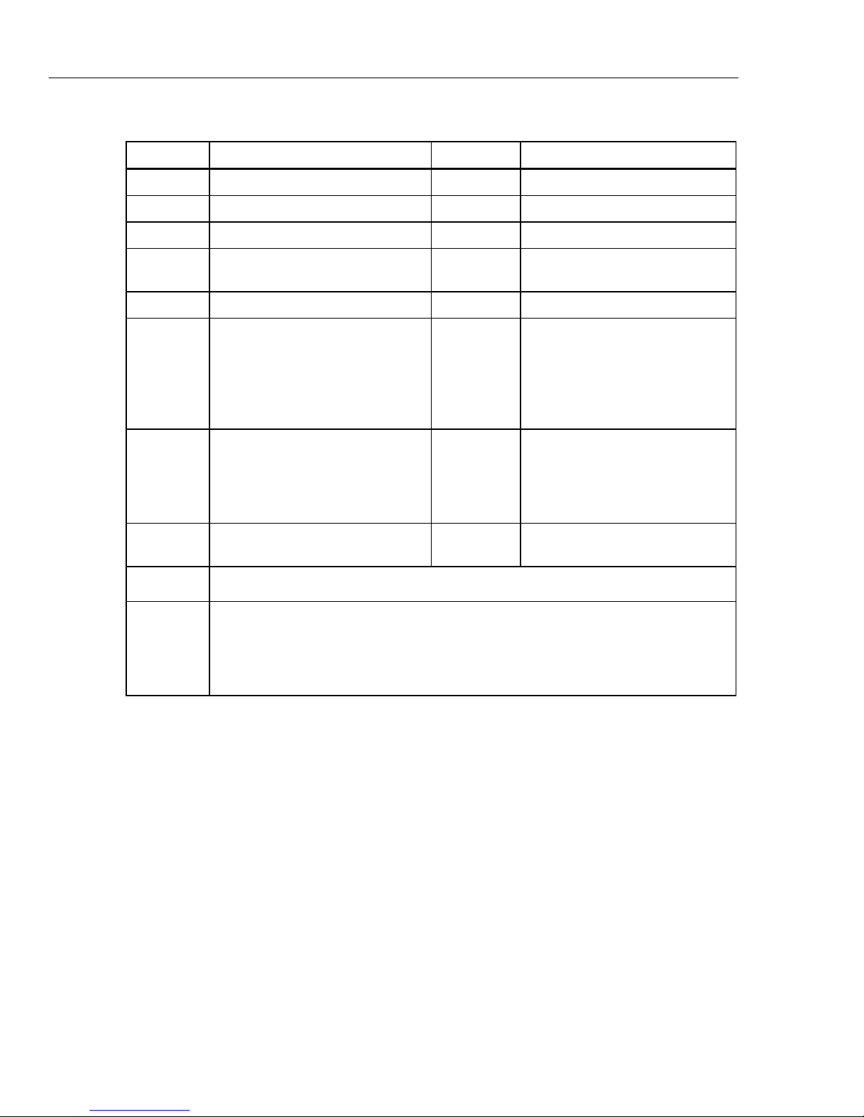
Maximum voltage between any Terminal and Earth Ground: 1000 V
Display (LCD) ........................................................ 4000 counts, updates 3/sec
Battery Type .......................................................... 2 AA, IEC LR6
Battery Life ............................................................ 500 hours minimum (50 hours in LED Test mode without load. The
hours with load depends on the type of LED under test.)
Temperature
Operating ............................................................ 0 °C to 40 °C
Storage ............................................................... -30 °C to 60 °C
Relative Humidity
Operating Humidity ............................................. Non-condensing (<10 °C); ≤90 % RH from 10 °C to 30 °C; ≤75 % RH
at 30 °C to 40 °C
Operating Humidity, 40 MΩRange..................... ≤80 % RH at 10 °C to 30 °C; ≤70 % RH at 30 °C to 40 °C
Altitude
Operating ............................................................ 2000 m
Storage ............................................................... 12 000 m
Temperature Coefficient.......................................0.1 X (specified accuracy) / °C (<18 °C or >28 °C)
Fuse protection for current inputs...................... 440 mA, 1000 V, IR 10 kA min
11 A, 1000 V, IR 20 kA min
Size (HxWxL) ......................................................... 183 mm x 91 mm x 49.5 mm
Weight.................................................................... 455 g
Ingress Protection ................................................ IEC 60529: IP40 non-operating
Safety ..................................................................... IEC 61010-1: Pollution degree 2
IEC 61010-2-033: CAT III 600 V, CAT II 1000 V
Electromagnetic Compatibility
International ........................................................ IEC 61326-1: Basic Electromagnetic Environment: IEC 61326-2-2
CISPR 11: Group 1, Class A
Group 1: Equipment has intentionally generated and/or use
conductively coupled radio-frequency energy which is necessary
for the internal functioning of the equipment itself.
Class A: Equipment is suitable for use in all establishments other
than domestic and those directly connected to a low voltage power
supply network which supplies buildings used for domestic
purposes. There may be potential difficulties in ensuring
electromagnetic compatibility in other environments, due to
conducted and radiated disturbances.
Korea (KCC) ...................................................... Class A Equipment (Industrial Broadcasting & Communication
Equipment)
Class A: Equipment meets requirements for industrial
electromagnetic wave equipment and the seller or user should take
notice of it. This equipment is intended for use in business
environments and not to be used in homes.
USA (FCC).......................................................... 47 CFR 15 subpart B. This product is considered an exempt device per
clause 15.103.

15B+/17B+/18B+
Calibration Manual
6
Accuracy Specifications
Accuracy is specified for 1 year after calibration, at operating temperatures of
18 °C to 28 °C, relative humidity at 0 % to 75 %. Accuracy specifications take the
form of: ±([% of Reading] + [Number of Least Significant Digits]).
AC and DC Voltage
Function Range Resolution Accuracy
15B+ 17B+ 18B+
AC Volts (40 Hz – 500 Hz)[1]
4.000 V
40.00 V
400.0 V
1000 V
0.001 V
0.01 V
0.1 V
1 V
1.0 % + 3 1.0 % + 3 1.0 % + 3
AC Millivolts
400.0 mV 0.1 mV 3.0 % + 3 3.0 % + 3 3.0 % + 3
DC Millivolts
400.0 mV 0.1 mV 1.0 % + 10 1.0 % + 10 1.0 % + 10
DC Volts
4.000 V
40.00 V
400.0 V
1000 V
0.001 V
0.01 V
0.1 V
1 V
0.5 % + 3 0.5 % + 3 0.5 % + 3
[1] All ac, Hz, and duty cycle are specified from 1 % to 100 % of range. Inputs below 1 % of range are not specified.
AC and DC Current
Function Resolution Accuracy
15B+ 17B+ 18B+
AC Current μA
(40 Hz – 400 Hz)
0.1 μA
1 μA 1.5 % + 3 1.5 % + 3 1.5 % + 3
AC current mA
(40 Hz – 400 Hz)
0.01 mA
0.1 mA 1.5 % + 3 1.5 % + 3 1.5 % + 3
AC current A[1]
(40 Hz – 400 Hz)
0.001 A
0.01 A 1.5 % + 3 1.5 % + 3 1.5 % + 3
DC current μA
0.1 μA
1 μA 1.5 % + 3 1.5 % + 3 1.5 % + 3
DC current mA
0.01 mA
0.1 mA 1.5 % + 3 1.5 % + 3 1.5 % + 3
DC current A[1]
0.001 A
0.01 A 1.5 % + 3 1.5 % + 3 1.5 % + 3

Digital Multimeter
Accuracy Specifications
7
Diode Test, Temperature, Resistance, Capacitance, Frequency, and Duty Cycle
Function Range Resolution Accuracy
15B+ 17B+ 18B+
Diode Test[1]
2.000 V 0.001 V 10 %
Temperature
50.0 °C –
400.0 °C
0 °C – 50.0 °C
-55.0 °C – 0 °C
0.1 °C _
2 % +1 °C
2 °C
9 % +2 °C
_
Resistance
(Ohms)
400.0 Ω
4.000 kΩ
40.00 kΩ
400.0 kΩ
4.000 MΩ
40.00 MΩ
0.1 Ω
0.001 kΩ
0.01 kΩ
0.1 kΩ
0.001 MΩ
0.01 MΩ
0.5 % + 3
0.5 % + 2
0.5 % + 2
0.5 % + 2
0.5 % + 2
1.5 % + 3
0.5 % + 3
0.5 % + 2
0.5 % + 2
0.5 % + 2
0.5 % + 2
1.5 % + 3
0.5 % + 3
0.5 % + 2
0.5 % + 2
0.5 % + 2
0.5 % + 2
1.5 % + 3
Capacitance[2]
40.00 nF
400.0 nF
4.000 μF
40.00 μF
400.0 μF
1000 μF
0.01 nF
0.1 nF
0.001 μF
0.01 μF
0.1 μF
1 μF
2 % + 5
2 % + 5
5 % + 5
5 % + 5
5 % + 5
5 % + 5
2 % + 5
2 % + 5
5 % + 5
5 % + 5
5 % + 5
5 % + 5
2 % + 5
2 % + 5
5 % + 5
5 % + 5
5 % + 5
5 % + 5
Frequency[3]
(10 Hz – 100 kHz)
Hz
50.00 Hz
500.0 Hz
5.000 kHz
50.00 kHz
100.0 kHz
0.01 Hz
0.1 Hz
0.001 kHz
0.01 kHz
0.1 kHz
_ 0.1 % + 3 0.1 % + 3
Duty Cycle[2] 1 % to 99 % 0.1 % _ 1 % typical [4] 1 %
typical[4]
[1] Typically, open circuit test voltage is 2.0 V and short circuit current is <0.6 mA.
[2] Specifications do not include errors due to test lead capacitance and capacitance floor (may be up to 1.5 nF in the 40 nF
range).
[3] All ac, Hz, and duty cycle are specified from 1 % to 100 % of range. Inputs below 1 % of range are not specified.
[4] Typical means when the frequency is at 50 Hz or 60 Hz and the duty cycle is between 10 % and 90 %.

15B+/17B+/18B+
Calibration Manual
8
LED Test and Continuity Threshold
Function Illumination Range Measurement Range Resolution Accuracy
LED VFTest [1] (LED Test
Socket) 1.00 V to 6.00 V NA NA NA
LED VFTest [2] (Test Leads) 1.00 V to 6.00 V 1.00 V to 6.00 V 0.01 V 10 % [3]
Continuity Threshold NA NA NA 70 Ω
[1] Open circuit test voltage is ±12 V and short-circuit current is <±5 mA (typical).
[2] Open circuit test voltage is ±12 V and short-circuit current is <±3 mA (typical).
[3] VF measurement with driving current under 2.2 mA ±0.4 mA.
Input Characteristics
Function Overload
Protection Input Impedance
(Nominal) Common Mode
Rejection Ratio Normal Mode
Rejection Ratio
AC Volts 1000 V [1] >10 MΩ, <100 pF >60 dB at dc,
50 Hz or 60 Hz _
AC Millivolts 400 mV >1 MΩ, <100 pF >80 dB at dc,
50 Hz or 60 Hz _
DC Volts 1000 V [1] >10 MΩ, <100 pF >100 dB at dc,
50 Hz or 60 Hz
>60 dB at
50 Hz or 60 Hz
DC Millivolts 400 mV >1 MΩ, <100 pF >80 dB at dc,
50 Hz or 60 Hz _
[1] 106V Hz Max

Digital Multimeter
Accuracy Specifications
9
hStatic Awareness h
XSemiconductors and integrated circuits can be damaged by electrostatic
discharge during handling. This notice explains how to minimize damage to
these components.
1. Understand the problem.
2. Learn the guidelines for proper handling.
3. Use the proper procedures, packaging, and bench techniques.
Follow these practices to minimize damage to static sensitive parts.
WWarning
To prevent electric shock or personal injury. De-
energize the product and all active circuits before
opening a product enclosure, touching or handling
any PCBs or components.
•Minimize handling.
•Handle static-sensitive
parts by non-conductive
edges.
•Do not slide static-
sensitive components
over any surface.
•When removing plug-in
assemblies, handle only
by non-conductive
edges.
•Never touch open-edge
connectors except at a
static-free work station.
•Keep parts in the original
containers until ready for
use.
•Use static shielding
containers for handling
and transport.
•Avoid plastic, vinyl, and
Styrofoam®in the work
area.
•Handle static-sensitive
parts only at a static-
free work station.
•Put shorting strips on
the edge of the
connector to help
protect installed static-
sensitive parts.
•Use anti-static type
solder extraction tools
only.
•Use grounded-tip
soldering irons only.

15B+/17B+/18B+
Calibration Manual
10
Disassembly
XWWarning
To prevent false readings, which could lead to possible electric
shock or personal injury, replace the batteries as soon as the
low battery indicator () appears.
To prevent damage or injury:
• Install ONLY replacement fuses with the specified
amperage, voltage, and interrupt ratings.
• Disconnect test leads before opening the case or the
battery door.
To remove the battery door and battery for adjustments and calibration, see
Figure 1.
icr01.eps
Figure 1. Remove the battery
Performance Tests
Use the performance tests to make sure the UUT is operating properly and to
make sure the UUT is accurate. If the UUT fails any part of the performance test,
repair and/or calibration adjustment are required. See the Calibration sections for
calibration adjustment. If the UUT still fails to meet the range indicated, see How
to Contact Fluke.
Table 2 lists the equipment required for the performance tests.
Table 2. Required Equipment for Performance Test 15B+ and 17B+
Equipment Recommended Model
Calibrator FLUKE 5522A

Digital Multimeter
Performance Tests
11
Performance Tests for the 15B+ and 17B+
Before doing the performance test, make sure to warm up the calibrator.
To test each function and operating ranges:
1. For each step in Table 3, set the UUT to the specified function and range.
2. Connect the source to the input jacks on the UUT.
3. Apply the output from the source.
4. Make sure the readings on the UUT display are within the limits in Table 3.
Table 3. Performance Specifications for 15B+ and 17B+
Step Function
Calibrator output
15B+ 17B+
UUT reading limit
Value Frequency
or Amplitude Lower
Limit Upper
Limit
1
VAC
3.5 V 50 Hz √√3.462 3.538
2 35 V 50 Hz √√34.62 35.38
3 35 V 500 Hz √√34.62 35.38
4 350 V 50 Hz √√346.2 353.8
5 1000 V 50 Hz √√986 1014
6
VAC/Freq.
45 Hz 1 V X √44.92 45.08
7 5 KHz 1 V X √4.992 5.008
8 100 KHz 3 V X √99.6 100.4
9 VAC/Duty 50 Hz 3 V (Square
Wave) X √49.5 50.5
10
VDC
3.5 V 0 Hz √√3.480 3.520
11 35 V 0 Hz √√34.80 35.20
12 350 V 0 Hz √√348.0 352.0
13 -1000 V 0 Hz √√-1008 -992
14 mVDC 350 mV 0 Hz √√345.4 354.6
15 mVAC 350 mV 500 Hz √√339.2 360.8

15B+/17B+/18B+
Calibration Manual
12
Table 0-3. Performance Specifications for 15B+ and 17B+ (cont.)
Step Function
Calibrator output
15B+ 17B+
UUT reading limit
Value Frequency
or Amplitude Lower
Limit Upper
Limit
16
OHM
0 ΩΩ √√-0.3 0.3
17 350 ΩΩ √√348.0 352.0
18 3.5 kΩΩ √√3.480 3.520
19 35 kΩΩ √√34.80 35.20
20 350 kΩΩ √√348.0 352.0
21 3.5 MΩΩ √√3.480 3.520
22 10 MΩΩ √√9.82 10.18
23 BEEPER ON 40 ΩΩ√√X X
24 DIODE 0.7 V 0 Hz √√0.622 0.778
25
CAP
35 nF Ω√√34.24 35.76
26 350 nF Ω√√342.4 357.6
27 3.5 μF Ω√√3.320 3.680
28 35 μF Ω√√33.20 36.80
29 350 μF Ω√√332.0 368.0
30 ADC 3.5 A 0 Hz √√3.444 3.556
31 -10 A 0 Hz √√-10.18 -9.82
32 AAC 3.5 A 50 Hz √√3.444 3.556
33 10 A 400 Hz √√9.82 10.18
34 mADC 35 mA 0 Hz √√34.44 35.56
35 -350 mA 0 Hz √√-355.6 -344.4
36 mAAC 35 mA 400 Hz √√34.44 35.56
37 350 mA 50 Hz √√344.4 355.6
38 μADC 350 μA 0 Hz √√344.4 355.6
39 -3500 μA 0 Hz √√-3556 -3444
40 μAAC 350 μA 40 Hz √√344.4 355.6
41 3500 μA 400 Hz √√3444 3556
42
Temp
-50 °C X X √-56.4 -43.6
43 35 °C X X √33.0 37.0
44 400 °C X X √391.0 409.0

Digital Multimeter
Performance Tests
13
Performance Test for 18B+
Before doing the performance test, make sure to warm up the calibrator.
To test each function and operating ranges:
1. For each step in Table 4, set the UUT to the specified function and range.
2. Connect the source to the input jacks on the UUT.
3. Apply the output from the source.
4. Make sure the readings on the UUT display are within the limits in Table 4.
5. For the LED test, put the LEDs as shown in Figure 2. The test passes if the
LED lights.
Table 4. Performance Specifications for 18B+
Step Function
Calibrator Output UUT reading limit
Value Frequency or
Amplitude Lower Limit Upper Limit
1
VAC
3.5 V 50 Hz 3.462 3.538
2 35 V 50 Hz 34.62 35.38
3 35 V 500 Hz 34.62 35.38
4 350 V 50 Hz 346.2 353.8
5 1000 V 50 Hz 986 1014
6
VAC/Freq.
45 Hz 1 V 44.92 45.08
7 5 KHz 1 V 4.992 5.008
8 100 KHz 3 V 99.6 100.4
9 VAC/Duty 50 Hz 3 V (Square
Wave) 49.5 50.5
10
VDC
3.5 V 0 Hz 3.480 3.520
11 35 V 0 Hz 34.80 35.20
12 350 V 0 Hz 348.0 352.0
13 -1000 V 0 Hz -1008 -992
14 mVDC 350 mV 0 Hz 345.4 354.6
15 mVAC 350 mV 500 Hz 339.2 360.8

15B+/17B+/18B+
Calibration Manual
14
Table 4. Performance Specifications for 18B+ (cont.)
Step Function
Calibrator Output UUT reading limit
Value Frequency or
Amplitude Lower Limit Upper Limit
16
OHM
0 ΩΩ-0.3 0.3
17 350 ΩΩ348.0 352.0
18 3.5 kΩΩ3.480 3.520
19 35 kΩΩ34.80 35.20
20 350 kΩΩ348.0 352.0
21 3.5 mΩΩ3.480 3.520
22 10 mΩΩ9.82 10.18
23 BEEPER ON 40 ΩΩX X
24 DIODE 0.7 V 0 Hz 0.622 0.778
25
CAP
35 nF Ω32.75 37.25
26 350 nF Ω342.4 357.6
27 3.5 μF Ω3.320 3.680
28 35 μF Ω33.20 36.80
29 350 μF Ω332.0 368.0
30 ADC 3.5 A 0 Hz 3.444 3.556
31 -10 A 0 Hz -10.18 -9.82
32 AAC 3.5 A 50 Hz 3.444 3.556
33 10 A 400 Hz 9.82 10.18
34 mADC 35 mA 0 Hz 34.44 35.56
35 -350 mA 0 Hz -355.6 -344.4
36 mAAC 35 mA 400 Hz 34.44 35.56
37 350 mA 50 Hz 344.4 355.6
38 μADC 350 μA 0 Hz 344.4 355.6
39 -3500 μA 0 Hz -3556 -3444
40 μAAC 350 μA 40 Hz 344.4 355.6
41 3500 μA 400 Hz 3444 3556
42 LED -5.5 V 0 Hz -6.05 -4.95
43 5.5 V 0 Hz 4.95 6.05

Digital Multimeter
Calibration Procedures
15
icr08.eps
Figure 2. LED Test
Calibration Procedures
Table 5 list equipment that is required to calibrate the Product.
Table 5. Required Equipment for Calibration
Equipment Required Characteristics Recommended Model
Calibrator FLUKE 5522A
Potentiometer (17B+) Manually adjustable
To enter calibration mode:
1. Remove the battery door and battery. See Figure 1.
2. Remove the calibration sticker. See Figure 3.
icr06.eps
Figure 3. Remove Calibration Sticker
3. See Figure 4 to make the connections to power and a calibrator:
•Use a contact spring to connect to a 3 V dc power supply.
Other manuals for 15B
3
This manual suits for next models
2
Table of contents
Other Fluke Multimeter manuals

Fluke
Fluke 867B User manual

Fluke
Fluke 77 Use and care manual

Fluke
Fluke 114 User manual

Fluke
Fluke 116 User manual

Fluke
Fluke 112 User manual

Fluke
Fluke 8024B User manual

Fluke
Fluke 27-II User manual

Fluke
Fluke LinkRunner Pro LRPRO-1000 User manual

Fluke
Fluke 175 Use and care manual

Fluke
Fluke CNX 3000 Use and care manual