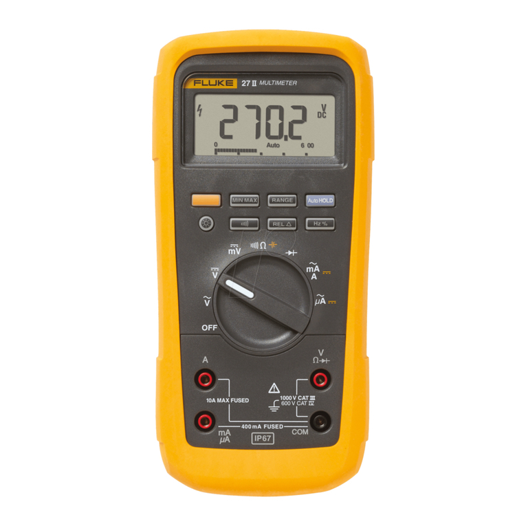
Fluke 279 FC User manual

LIMITED WARRANTY AND LIMITATION OF LIABILITY
Each Fluke product is warranted to be free from defects in material and workmanship under normal use and service. The warranty period is
three years and begins on the date of shipment. Parts, product repairs, and services are warranted for 90 days. This warranty extends only to
the original buyer or end-user customer of a Fluke authorized reseller, and does not apply to fuses, disposable batteries, or to any product
which, in Fluke's opinion, has been misused, altered, neglected, contaminated, or damaged by accident or abnormal conditions of operation or
handling. Fluke warrants that software will operate substantially in accordance with its functional specifications for 90 days and that it has been
properly recorded on non-defective media. Fluke does not warrant that software will be error free or operate without interruption.
Fluke authorized resellers shall extend this warranty on new and unused products to end-user customers only but have no authority to extend a
greater or different warranty on behalf of Fluke. Warranty support is available only if product is purchased through a Fluke authorized sales
outlet or Buyer has paid the applicable international price. Fluke reserves the right to invoice Buyer for importation costs of repair/replacement
parts when product purchased in one country is submitted for repair in another country.
Fluke's warranty obligation is limited, at Fluke's option, to refund of the purchase price, free of charge repair, or replacement of a defective
product which is returned to a Fluke authorized service center within the warranty period.
To obtain warranty service, contact your nearest Fluke authorized service center to obtain return authorization information, then send the
product to that service center, with a description of the difficulty, postage and insurance prepaid (FOB Destination). Fluke assumes no risk for
damage in transit. Following warranty repair, the product will be returned to Buyer, transportation prepaid (FOB Destination). If Fluke
determines that failure was caused by neglect, misuse, contamination, alteration, accident, or abnormal condition of operation or handling,
including overvoltage failures caused by use outside the product’s specified rating, or normal wear and tear of mechanical components, Fluke
will provide an estimate of repair costs and obtain authorization before commencing the work. Following repair, the product will be returned to
the Buyer transportation prepaid and the Buyer will be billed for the repair and return transportation charges (FOB Shipping Point).
THIS WARRANTY IS BUYER'S SOLE AND EXCLUSIVE REMEDY AND IS IN LIEU OF ALL OTHER WARRANTIES, EXPRESS OR IMPLIED,
INCLUDING BUT NOT LIMITED TO ANY IMPLIED WARRANTY OF MERCHANTABILITY OR FITNESS FOR A PARTICULAR PURPOSE.
FLUKE SHALL NOT BE LIABLE FOR ANY SPECIAL, INDIRECT, INCIDENTAL OR CONSEQUENTIAL DAMAGES OR LOSSES, INCLUDING
LOSS OF DATA, ARISING FROM ANY CAUSE OR THEORY.
Since some countries or states do not allow limitation of the term of an implied warranty, or exclusion or limitation of incidental or consequential
damages, the limitations and exclusions of this warranty may not apply to every buyer. If any provision of this Warranty is held invalid or
unenforceable by a court or other decision-maker of competent jurisdiction, such holding will not affect the validity or enforceability of any other
provision..
11/99
libpng version 1.6.13 - August 21, 2014
Copyright (c) 1998-2014 Glenn Randers-Pehrson
Copyright (c) 1996-1997 Andreas Dilger
Copyright (c) 1995-1996 Guy Eric Schalnat, Group 42, Inc
zlib version 1.2.8 - April 28th, 2013
Copyright (C) 1995-2013 Jean-loup Gailly and Mark Adler

i
Title Page
Introduction. . . . . . . . . . . . . . . . . . . . . . . . . . . . . . . . . . . . . . . . . . . . . . . . . . . . . . . . . . . . . . . . . . . . . . . . . . . . . .1
How to Contact Fluke. . . . . . . . . . . . . . . . . . . . . . . . . . . . . . . . . . . . . . . . . . . . . . . . . . . . . . . . . . . . . . . . . . . . . .2
Safety Information . . . . . . . . . . . . . . . . . . . . . . . . . . . . . . . . . . . . . . . . . . . . . . . . . . . . . . . . . . . . . . . . . . . . . . . .2
Fluke Connect™ Wireless System. . . . . . . . . . . . . . . . . . . . . . . . . . . . . . . . . . . . . . . . . . . . . . . . . . . . . . . . . . . .5
Radio Frequency Data . . . . . . . . . . . . . . . . . . . . . . . . . . . . . . . . . . . . . . . . . . . . . . . . . . . . . . . . . . . . . . . . . .5
Set Up for Fluke Connect App. . . . . . . . . . . . . . . . . . . . . . . . . . . . . . . . . . . . . . . . . . . . . . . . . . . . . . . . . . . . .5
Before You Start. . . . . . . . . . . . . . . . . . . . . . . . . . . . . . . . . . . . . . . . . . . . . . . . . . . . . . . . . . . . . . . . . . . . . . . . . .6
On/Off . . . . . . . . . . . . . . . . . . . . . . . . . . . . . . . . . . . . . . . . . . . . . . . . . . . . . . . . . . . . . . . . . . . . . . . . . . . . . . . 7
Hanging Strap . . . . . . . . . . . . . . . . . . . . . . . . . . . . . . . . . . . . . . . . . . . . . . . . . . . . . . . . . . . . . . . . . . . . . . . . . 7
Display Information . . . . . . . . . . . . . . . . . . . . . . . . . . . . . . . . . . . . . . . . . . . . . . . . . . . . . . . . . . . . . . . . . . . . .7
Hazardous Voltage . . . . . . . . . . . . . . . . . . . . . . . . . . . . . . . . . . . . . . . . . . . . . . . . . . . . . . . . . . . . . . . . .7
Test Lead Alert . . . . . . . . . . . . . . . . . . . . . . . . . . . . . . . . . . . . . . . . . . . . . . . . . . . . . . . . . . . . . . . . . . . .7
Display OL . . . . . . . . . . . . . . . . . . . . . . . . . . . . . . . . . . . . . . . . . . . . . . . . . . . . . . . . . . . . . . . . . . . . . . . . . . . . . . 7
Battery Charge . . . . . . . . . . . . . . . . . . . . . . . . . . . . . . . . . . . . . . . . . . . . . . . . . . . . . . . . . . . . . . . . . . . . . . . . 8
Setup Menu . . . . . . . . . . . . . . . . . . . . . . . . . . . . . . . . . . . . . . . . . . . . . . . . . . . . . . . . . . . . . . . . . . . . . . . . . . 10
Beeper. . . . . . . . . . . . . . . . . . . . . . . . . . . . . . . . . . . . . . . . . . . . . . . . . . . . . . . . . . . . . . . . . . . . . . . . . . 11
Auto Dim . . . . . . . . . . . . . . . . . . . . . . . . . . . . . . . . . . . . . . . . . . . . . . . . . . . . . . . . . . . . . . . . . . . . . . . . . . . . . . 11
Auto Off . . . . . . . . . . . . . . . . . . . . . . . . . . . . . . . . . . . . . . . . . . . . . . . . . . . . . . . . . . . . . . . . . . . . . . . . . 11
Table of Contents

279 FC
Users Manual
ii
Temperature Units. . . . . . . . . . . . . . . . . . . . . . . . . . . . . . . . . . . . . . . . . . . . . . . . . . . . . . . . . . . . . . . . .11
Image Memory Management. . . . . . . . . . . . . . . . . . . . . . . . . . . . . . . . . . . . . . . . . . . . . . . . . . . . . . . . .12
Calibration . . . . . . . . . . . . . . . . . . . . . . . . . . . . . . . . . . . . . . . . . . . . . . . . . . . . . . . . . . . . . . . . . . . . . . .12
Device Information. . . . . . . . . . . . . . . . . . . . . . . . . . . . . . . . . . . . . . . . . . . . . . . . . . . . . . . . . . . . . . . . .12
Inputs. . . . . . . . . . . . . . . . . . . . . . . . . . . . . . . . . . . . . . . . . . . . . . . . . . . . . . . . . . . . . . . . . . . . . . . . . . . . . . .13
Rotary Switch and Pushbuttons. . . . . . . . . . . . . . . . . . . . . . . . . . . . . . . . . . . . . . . . . . . . . . . . . . . . . . . . . . .13
IR Camera Mode . . . . . . . . . . . . . . . . . . . . . . . . . . . . . . . . . . . . . . . . . . . . . . . . . . . . . . . . . . . . . . . . . . . . . . . .16
Basic Measurements . . . . . . . . . . . . . . . . . . . . . . . . . . . . . . . . . . . . . . . . . . . . . . . . . . . . . . . . . . . . . . . . . . . . .17
AC and DC Voltage Measurements. . . . . . . . . . . . . . . . . . . . . . . . . . . . . . . . . . . . . . . . . . . . . . . . . . . . . . . .17
Volts/Hertz Ratio . . . . . . . . . . . . . . . . . . . . . . . . . . . . . . . . . . . . . . . . . . . . . . . . . . . . . . . . . . . . . . . . . . . . . .19
Low-Pass Filter . . . . . . . . . . . . . . . . . . . . . . . . . . . . . . . . . . . . . . . . . . . . . . . . . . . . . . . . . . . . . . . . . . . . . . .19
Resistance Measurements . . . . . . . . . . . . . . . . . . . . . . . . . . . . . . . . . . . . . . . . . . . . . . . . . . . . . . . . . . . . . .20
Capacitance Measurements . . . . . . . . . . . . . . . . . . . . . . . . . . . . . . . . . . . . . . . . . . . . . . . . . . . . . . . . . . . . .21
Continuity Test. . . . . . . . . . . . . . . . . . . . . . . . . . . . . . . . . . . . . . . . . . . . . . . . . . . . . . . . . . . . . . . . . . . . . . . .22
AC Current Measurements . . . . . . . . . . . . . . . . . . . . . . . . . . . . . . . . . . . . . . . . . . . . . . . . . . . . . . . . . . . . . .23
Diode Test . . . . . . . . . . . . . . . . . . . . . . . . . . . . . . . . . . . . . . . . . . . . . . . . . . . . . . . . . . . . . . . . . . . . . . . . . . .25
Frequency Measurements. . . . . . . . . . . . . . . . . . . . . . . . . . . . . . . . . . . . . . . . . . . . . . . . . . . . . . . . . . . . . . .27
Measurement Features . . . . . . . . . . . . . . . . . . . . . . . . . . . . . . . . . . . . . . . . . . . . . . . . . . . . . . . . . . . . . . . . . . .29
MIN MAX AVG Record Mode . . . . . . . . . . . . . . . . . . . . . . . . . . . . . . . . . . . . . . . . . . . . . . . . . . . . . . . . . . . .29
Display Hold. . . . . . . . . . . . . . . . . . . . . . . . . . . . . . . . . . . . . . . . . . . . . . . . . . . . . . . . . . . . . . . . . . . . . . . . . .30
Auto Range and Manual Range . . . . . . . . . . . . . . . . . . . . . . . . . . . . . . . . . . . . . . . . . . . . . . . . . . . . . . . . . .31
AC Zero Input Behavior of True-rms Meters . . . . . . . . . . . . . . . . . . . . . . . . . . . . . . . . . . . . . . . . . . . . . . . . .31
SmartView® Software . . . . . . . . . . . . . . . . . . . . . . . . . . . . . . . . . . . . . . . . . . . . . . . . . . . . . . . . . . . . . . . . . . . .32
Firmware Updates . . . . . . . . . . . . . . . . . . . . . . . . . . . . . . . . . . . . . . . . . . . . . . . . . . . . . . . . . . . . . . . . . . . . .32
IR Image Management . . . . . . . . . . . . . . . . . . . . . . . . . . . . . . . . . . . . . . . . . . . . . . . . . . . . . . . . . . . . . . . . .33

Contents (cont.)
iii
Maintenance. . . . . . . . . . . . . . . . . . . . . . . . . . . . . . . . . . . . . . . . . . . . . . . . . . . . . . . . . . . . . . . . . . . . . . . . . . . .33
Multimeter Care. . . . . . . . . . . . . . . . . . . . . . . . . . . . . . . . . . . . . . . . . . . . . . . . . . . . . . . . . . . . . . . . . . . . . . .34
Lens Care . . . . . . . . . . . . . . . . . . . . . . . . . . . . . . . . . . . . . . . . . . . . . . . . . . . . . . . . . . . . . . . . . . . . . . . . . . .34
Parts and Accessories . . . . . . . . . . . . . . . . . . . . . . . . . . . . . . . . . . . . . . . . . . . . . . . . . . . . . . . . . . . . . . . . . . . .34
Specifications . . . . . . . . . . . . . . . . . . . . . . . . . . . . . . . . . . . . . . . . . . . . . . . . . . . . . . . . . . . . . . . . . . . . . . . . . . .37
Detailed Specifications. . . . . . . . . . . . . . . . . . . . . . . . . . . . . . . . . . . . . . . . . . . . . . . . . . . . . . . . . . . . . . . . . . . .39
AC Voltage Measurements . . . . . . . . . . . . . . . . . . . . . . . . . . . . . . . . . . . . . . . . . . . . . . . . . . . . . . . . . . . . . .39
DC Voltage, Continuity, Resistance, Diode Test, and Capacitance Measurements . . . . . . . . . . . . . . . . . . . 40
AC Current with iFlex i2500. . . . . . . . . . . . . . . . . . . . . . . . . . . . . . . . . . . . . . . . . . . . . . . . . . . . . . . . . . . . . .41
Frequency Measurement. . . . . . . . . . . . . . . . . . . . . . . . . . . . . . . . . . . . . . . . . . . . . . . . . . . . . . . . . . . . . . . . 41
Input Characteristics . . . . . . . . . . . . . . . . . . . . . . . . . . . . . . . . . . . . . . . . . . . . . . . . . . . . . . . . . . . . . . . . . . .42
MIN MAX Recording . . . . . . . . . . . . . . . . . . . . . . . . . . . . . . . . . . . . . . . . . . . . . . . . . . . . . . . . . . . . . . . . . . . 42
Infrared Camera . . . . . . . . . . . . . . . . . . . . . . . . . . . . . . . . . . . . . . . . . . . . . . . . . . . . . . . . . . . . . . . . . . . . . . 43

279 FC
Users Manual
iv

v
Table Title Page
1. Symbols . . . . . . . . . . . . . . . . . . . . . . . . . . . . . . . . . . . . . . . . . . . . . . . . . . . . . . . . . . . . . . . . . . . . 4
2. Setup Menu Functions . . . . . . . . . . . . . . . . . . . . . . . . . . . . . . . . . . . . . . . . . . . . . . . . . . . . . . . . 10
3. Inputs . . . . . . . . . . . . . . . . . . . . . . . . . . . . . . . . . . . . . . . . . . . . . . . . . . . . . . . . . . . . . . . . . . . . .13
4. Rotary Switch Positions . . . . . . . . . . . . . . . . . . . . . . . . . . . . . . . . . . . . . . . . . . . . . . . . . . . . . . . 14
5. Pushbuttons . . . . . . . . . . . . . . . . . . . . . . . . . . . . . . . . . . . . . . . . . . . . . . . . . . . . . . . . . . . . . . . . 15
6. Accessories and Replacement Parts . . . . . . . . . . . . . . . . . . . . . . . . . . . . . . . . . . . . . . . . . . . . . 35
List of Tables

279 FC
Users Manual
vi

vii
Figure Title Page
1. Fluke Connect™ . . . . . . . . . . . . . . . . . . . . . . . . . . . . . . . . . . . . . . . . . . . . . . . . . . . . . . . . . . . . .5
2. Hanging Strap . . . . . . . . . . . . . . . . . . . . . . . . . . . . . . . . . . . . . . . . . . . . . . . . . . . . . . . . . . . . . . .7
3. Battery Charge. . . . . . . . . . . . . . . . . . . . . . . . . . . . . . . . . . . . . . . . . . . . . . . . . . . . . . . . . . . . . . .9
4. AC and DC Voltage Measurements. . . . . . . . . . . . . . . . . . . . . . . . . . . . . . . . . . . . . . . . . . . . . . 18
5. Low-Pass Filter . . . . . . . . . . . . . . . . . . . . . . . . . . . . . . . . . . . . . . . . . . . . . . . . . . . . . . . . . . . . . . . . . . 19
6. Volt/Hertz Ratio . . . . . . . . . . . . . . . . . . . . . . . . . . . . . . . . . . . . . . . . . . . . . . . . . . . . . . . . . . . . . 19
7. Resistance Measurements. . . . . . . . . . . . . . . . . . . . . . . . . . . . . . . . . . . . . . . . . . . . . . . . . . . . . 20
8. Capacitance Measurements . . . . . . . . . . . . . . . . . . . . . . . . . . . . . . . . . . . . . . . . . . . . . . . . . . .21
9. Continuity Tests . . . . . . . . . . . . . . . . . . . . . . . . . . . . . . . . . . . . . . . . . . . . . . . . . . . . . . . . . . . . .22
10. AC Current Measurements . . . . . . . . . . . . . . . . . . . . . . . . . . . . . . . . . . . . . . . . . . . . . . . . . . . . 24
11. Diode Test . . . . . . . . . . . . . . . . . . . . . . . . . . . . . . . . . . . . . . . . . . . . . . . . . . . . . . . . . . . . . . . . .26
12. Frequency Measurement . . . . . . . . . . . . . . . . . . . . . . . . . . . . . . . . . . . . . . . . . . . . . . . . . . . . . . 28
13. Accessories and Replacement Parts . . . . . . . . . . . . . . . . . . . . . . . . . . . . . . . . . . . . . . . . . . . . 36
List of Figures

279 FC
Users Manual
viii

1
Introduction
The 279 FC True-rms Thermal Multimeter (the Multimeter or
Product) is a digital multimeter with an integrated thermal
imaging camera.
The Multimeter measures or tests:
•
AC voltage
•
AC current with the iFlex
•
DC voltage
•
Volts/Hertz ratio
•
Resistance
•
Capacitance
•
Continuity
•
Diodes
•
Frequency
Use the IR camera for:
•
Temperature measurements
•
Thermal images
Use the detachable iFlex (Flexible Current Probe) accessory
for:
•
AC current measurement
•
Improved access to awkward-sized conductors and wires
The Multimeter supports the Fluke Connect™ Wireless
System (may not be available in all regions). Fluke Connect™
is a system that wirelessly connects your Multimeter with an
app on your smartphone or tablet. The app shows the
Multimeter measurement or thermal image on your
smartphone or tablet display. You can save these
measurements and images to Fluke Cloud™ storage and
share with your team.
See Fluke Connect™ Wireless System on page 5 for more
information.

279 FC
Users Manual
2
Safety Information
A Warning identifies conditions and procedures that are
dangerous to the user. A Caution identifies conditions and
procedures that can cause damage to the Product or the
equipment under test.
XW Warning
To prevent possible electrical shock, fire, or
personal injury:
•
Carefully read all instructions.
•
Read all safety information before you use the
Product.
•
Use the Product only as specified, or the
protection supplied by the Product can be
compromised.
•
Comply with local and national safety codes.
Use personal protective equipment (approved
rubber gloves, face protection, and flame-
resistant clothes) to prevent shock and arc blast
injury where hazardous live conductors are
exposed.

True-rms Thermal Multimeter
Safety Information
3
•
Examine the case before you use the Product.
Look for cracks or missing plastic. Carefully
look at the insulation around the terminals.
•
Do not use the Flexible Current Probe if it has
damaged insulation, exposed metal, or if the
wear indicator is visible.
•
Do not use test leads if they are damaged.
Examine the test leads for damaged insulation,
exposed metal, or if the wear indicator shows.
Check test lead continuity.
•
The battery door must be closed and locked
before you operate the Product.
•
Do not touch voltages >30 V ac rms, 42 V ac
peak, or 60 V dc.
•
Use Product-approved measurement category
(CAT), voltage, and amperage rated accessories
(probes, test leads, and adapters) for all
measurements.
•
Do not exceed the Measurement Category (CAT)
rating of the lowest rated individual component
of a Product, probe, or accessory.
•
Measure a known voltage first to make sure that
the Product operates correctly.
•
Limit operation to the specified measurement
category, voltage, or amperage ratings.
•
Do not use the Product above its rated
frequency.
•
Do not use in CAT III or CAT IV environments
without the protective cap installed on test
probe. The protective cap decreases the
exposed probe metal to <4 mm. This decreases
the possibility of arc flash from short circuits.
•
Do not apply more than the rated voltage,
between the terminals or between each terminal
and earth ground.
•
De-energize the circuit or wear personal
protective equipment in compliance with local
requirements before you apply or remove the
Flexible Current Probe.

279 FC
Users Manual
4
Symbols used on the Product and in this manual are
explained in Table 1. Table 1. Symbols
Symbol Description Symbol Description
WWARNING. RISK OF DANGER. Battery
Consult user documentation. )Certified by CSA Group to North American safety standards.
XWARNING. HAZARDOUS VOLTAGE.
Risk of electric shock. PConforms to European Union directives.
TDouble Insulated Conforms to relevant Australian EMC standards.
ÃConforms to relevant South Korean EMC Standards.
Measurement Category II is applicable to test and measuring circuits connected directly to utilization points (socket outlets and
similar points) of the low-voltage MAINS installation.
Measurement Category III is applicable to test and measuring circuits connected to the distribution part of the building’s low-
voltage MAINS installation.
Measurement Category IV is applicable to test and measuring circuits connected at the source of the building’s low-voltage
MAINS installation.
This product contains a Lithium-ion battery. Do not mix with the solid waste stream. Spent batteries should be disposed of by a
qualified recycler or hazardous materials handler per local regulations. Contact your authorized Fluke Service Center for recycling
information.
~
This product complies with the WEEE Directive marking requirements. The affixed label indicates that you must not discard this
electrical/electronic product in domestic household waste. Product Category: With reference to the equipment types in the WEEE
Directive Annex I, this product is classed as category 9 "Monitoring and Control Instrumentation" product. Do not dispose of this
product as unsorted municipal waste.

True-rms Thermal Multimeter
Fluke Connect™ Wireless System
5
Fluke Connect™ Wireless System
The Multimeter supports the Fluke Connect™ Wireless
System (may not be available in all regions). Fluke Connect™
uses low-power 802.15.4 wireless radio technology to
wirelessly connect the Multimeter with an app on your
smartphone or tablet. The wireless radio does not cause
interference with meter measurements.
The app shows measurements or thermal images on your
smartphone or tablet display, saves to Fluke Cloud™ storage,
and shares the information with your team.
Radio Frequency Data Note
Changes or modifications to the wireless 2.4 GHz
radio not expressly approved by Fluke Corporation
could void the user’s authority to operate the
equipment.
Set Up for Fluke Connect App
The Fluke Connect app works with Apple and Android mobile
products. The app is available for download from the Apple
App Store and Google Play.
To use Fluke Connect:
1. Turn on the Multimeter. See Figure 1.
12
34
Figure 1. Fluke Connect™

279 FC
Users Manual
6
2. Press to activate the radio on the Multimeter. shows
on the display.
3. On your smartphone, go to Settings > Bluetooth.
Verify that Bluetooth is turned on.
4. Go to the Fluke Connect App and in the list of connected
Fluke tools, select 279 FC.
You can now take, save, and share measurements with the
app.
To send an IR Camera image to the app, see page 16.
Before You Start
This section is information to know before you use the
Multimeter.
XWWarning
To prevent possible electrical shock, fire, or
personal injury:
•
Disconnect power and discharge all high-
voltage capacitors before you measure
resistance, continuity, capacitance, or a diode
junction.
•
Do not use the HOLD function to measure
unknown potentials. When HOLD is turned on,
the display does not change when a different
potential is measured.

True-rms Thermal Multimeter
Before You Start
7
On/Off
Push to turn on or turn off the Multimeter.
Hanging Strap
The Multimeter includes a hanging strap that allows you to
hang your Multimeter so you can take measurements hands-
free. See Figure 2.
Display Information
Hazardous Voltage
The hazardous voltage warning Xshows on the display
when the Multimeter detects a voltage ≥30 V.
Test Lead Alert
The display shows LEAD for a second when you turn the
function switch to or from the position. This is a reminder
to check that the correct accessory is connected.
Display OL
If the measurement value (does not include temperature
measurements) is over the limit, or outside the measurement
range, the Multimeter shows OL in the display.
Figure 2. Hanging Strap
12
4
3

279 FC
Users Manual
8
Battery Charge
XW Warning
To prevent a possible electrical shock, fire, or
personal injury:
•
Disconnect the battery charger and move the
Product or battery to a cool, non-flammable
location if the rechargeable battery becomes
hot (>50 °C) during the charge period.
•
Replace the rechargeable battery after 5 years
of moderate use or 2 years of heavy use.
Moderate use is defined as recharged twice a
week. Heavy use is defined as discharged to
cutoff and recharged daily.
•
Batteries contain hazardous chemicals that can
cause burns or explode. If exposure to
chemicals occurs, clean with water and get
medical aid.
•
Do not short the battery terminals together.
•
Do not disassemble or crush battery cells and
battery packs.
•
Do not put battery cells and battery packs near
heat or fire. Do not put in sunlight.
The Multimeter is packaged with the battery pack at <30 %
charge. Before first use, make sure the battery pack is fully
charged. The battery pack must be removed and charged
outside of the Multimeter. See Figure 3.
To remove and charge the battery pack:
1. Turn off the Multimeter and remove all test leads.
2. Extend the tilt stand to expose the battery door.
3. Turn the battery-door latch until the unlock symbol ()
aligns with the arrow.
4. Lift off the battery door/tilt stand.
5. Remove the battery pack and recharge.
After battery is fully recharged:
1. Place the battery pack into the battery compartment.
2. Install the battery door/tilt stand.
3. Turn the battery-door latch until the locked symbol ()
aligns with the arrow.
The display shows an icon for the battery status:
- 100 % charge
- 50 % charge
- 0 % charge

True-rms Thermal Multimeter
Before You Start
9
Figure 3. Battery Charge

279 FC
Users Manual
10
Setup Menu
The Setup Menu includes these functions:
•
on/off for the audible beeper
•
on/off for automatic backlight dimming
•
on/off for automatic power off (battery save)
•
unit selection for temperature measurements
•
image memory management
•
calibration procedure
•
information about your device
All setup functions remain as set when you turn off and turn on
the Multimeter.
To open the Setup Menu, push . Use the top row of
buttons to control actions within the Setup Menu. These
buttons correspond to the softkey labels that show on the
display. See Table 2.
Table 2. Setup Menu Functions
Button Softkey Action
NA Open the Setup Menu
Close the Setup Menu
Go back to previous menu
Move the menu highlight up
Move the menu highlight down
Accept a change to the setup
Open a submenu for selections
Other manuals for 279 FC
2
Table of contents
Other Fluke Multimeter manuals
Popular Multimeter manuals by other brands

ELCART
ELCART NI 2100 Operation manual

VOLTCRAFT
VOLTCRAFT 2446476 operating instructions

EXTOL PREMIUM
EXTOL PREMIUM 8831252 Translation of the original user manual

Keysight Technologies
Keysight Technologies U1282A Modification Recommended Service Note

Keysight
Keysight u1273a quick start guide

Actron
Actron Digital Multitester CP7674 instruction manual