Fluke 74X Series Use and care manual


i
Table of Contents
Title Page
Introduction ......................................................................................................... 1
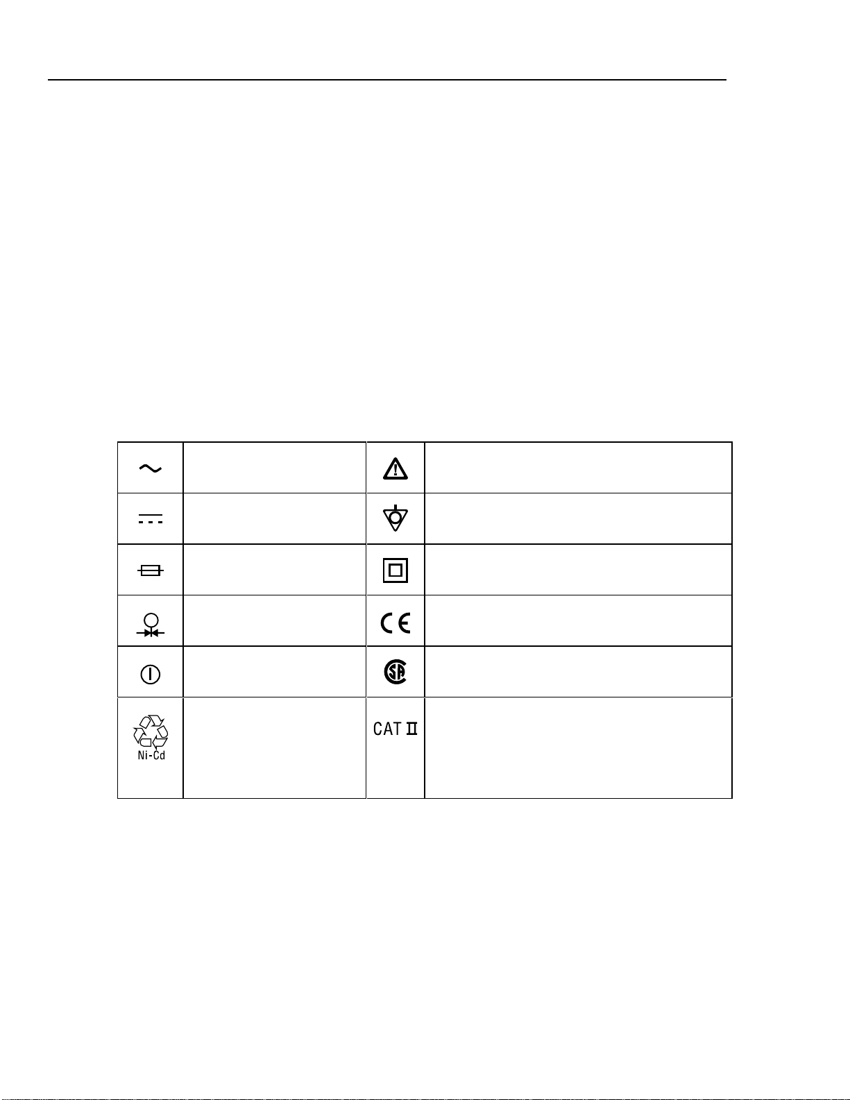
Safety Information............................................................................................... 1
Specifications....................................................................................................... 3
DC Voltage Measurement............................................................................... 3
AC Voltage Measurement............................................................................... 3
DC Current Measurement................................................................................ 4
Resistance Measurement ................................................................................. 4
Continuity Testing........................................................................................... 4
Frequency Measurement ................................................................................. 4
DC Voltage Output.......................................................................................... 5
DC Current Output.......................................................................................... 5
Resistance Sourcing ........................................................................................ 5
Frequency Sourcing......................................................................................... 6
Temperature, Thermocouples.......................................................................... 6
Temperature, Resistance Temperature Detectors............................................ 8
Loop Power Supply......................................................................................... 9
Top and Bottom Limits of Ranges with Auto Range On................................. 9
General Specifications......................................................................................... 10
Performance Verification Tests ........................................................................... 11
Equipment Required for Verification.............................................................. 11
How to Verify.................................................................................................. 11
DC Volts Measurement............................................................................... 12
AC Volts Measurement............................................................................... 14
DC Current Measurement ........................................................................... 15
Resistance Measurement............................................................................. 16
Frequency Measurement............................................................................. 17
DC Volts Source ......................................................................................... 18
DC Current Source...................................................................................... 19
Simulate Transmitter Function.................................................................... 20
Frequency Source........................................................................................ 22
Thermocouple Measure............................................................................... 23
Thermocouple Source ................................................................................. 24
RTD Measure, Four-Wire........................................................................... 25
RTD Measure, Three-Wire ......................................................................... 26
RTD Source ................................................................................................ 27
Loop Power................................................................................................. 28

74X Series
Calibration Manual
ii
HART Mode Verification.................................................................................... 29
Calibration........................................................................................................... 30
Equipment Required for Calibration ............................................................... 30
Calibration Status Indicator............................................................................. 31
Calibration Constant Out of Bounds ............................................................... 31
Order of Calibration ........................................................................................ 31
How to Calibrate ............................................................................................. 32
Adjustment of Potentiometers ............................................................................. 34
Replaceable Parts................................................................................................. 35
Service Centers.................................................................................................... 36

iii
List of Tables
Table Title Page
1. Definition of Symbols............................................................................................. 2
2. Equipment Required for Verification...................................................................... 11
3. DC Volts Measurement Verification Points............................................................ 13
4. AC Volts Measurement Verification Points............................................................ 14
5. DC Current Measurement Verification Points........................................................ 15
6. Resistance Measurement Verification Points.......................................................... 16
7. Frequency Measurement Verification Points.......................................................... 17
8. DC Volts Source Verification Points...................................................................... 18
9. DC Current Source Verification Points................................................................... 19
10. Simulate Transmitter Verification Points................................................................ 20
11. Resistance Source Verification Points .................................................................... 21
12. Frequency Source Verification Points..................................................................... 22
13. Temperature Measure Verification ......................................................................... 23
14. Temperature Source Verification (Type-K Thermocouple, ITS-90)....................... 24
15. RTD Measure Verification (100W Pt (385), Four-Wire Connection) .................... 25
16. RTD Measure Verification (100W Pt (385), Three-Wire Connection)................... 26
17. RTD Source Verification (100W Pt (385))............................................................. 27
18. Loop Power Verification......................................................................................... 28
19. Replacement Parts................................................................................................... 35

74X Series
Calibration Manual
iv

v
List of Figures
Figure Title Page
1. LCD Operating Environment Specification............................................................ 10
2. DC Volts and AC Volts Measurement Connections............................................... 12
3. DC Current Measurement Verification Connections .............................................. 15
4. Resistance Measurement Verification Connections................................................ 16
5. Frequency Measurement Verification Connections................................................ 17
6. DC Volts Source Verification Connections ............................................................ 18
7. DC Current Source Verification Connections......................................................... 19
8. Simulate Transmitter Verification Connections...................................................... 20
9. Resistance Source Verification Connections........................................................... 21
10. Frequency Source Verification Connections........................................................... 22
11. Temperature Measure (TC) Verification Connections............................................ 23
12. Four-Wire RTD Measure Verification Connections............................................... 25
13. Three-Wire RTD Measure Verification Connections ............................................. 26
14. Loop Power Verification Connections.................................................................... 28
15. HART Verification Connections............................................................................. 30
16. Proper and Improper Jumper Use ........................................................................... 33

74X Series
Calibration Manual
vi

1
Introduction
This manual contains information necessary to perform performance verification tests
and calibration adjustments on your Documenting Process Calibrator. General safety
information and product specifications are also included.
Unless stated otherwise, everything in this manual applies to the Fluke 741, 741B, 743,
743B and 744 Documenting Process Calibrators, also referred to as the 74X Series in this
manual.
The phone number in the USA and Canada for replacement parts is: 1-888-993-5853.
To contact Fluke, call one of the following telephone numbers:
USA and Canada: 1-888-99-FLUKE
(1-888-993-5853)
Europe: +31 402-678-200
Japan: +81-3-3434-0181
Singapore: +65-738-5655
Anywhere in the world: +1-425-356-5500
Or, visit Fluke’s Web site at www.fluke.com
Safety Information
This calibrator is designed and tested in accordance with IEC1010-1 and CAN/CSA
C22.2 No. 1010.1-92. Use the calibrator only as specified in this manual, otherwise the
protection provided by the calibrator may be impaired.
A Warning identifies conditions and actions that pose hazards to the user; a Caution
identifies conditions and actions that may damage the calibrator or the equipment under
test.
Symbols used on the calibrator and in this manual are explained in Table 1. To protect
yourself, follow these safety guidelines:
•Do not use the calibrator if it is damaged. Before you use the calibrator, inspect the
insulating cover. Look for cracks or missing plastic. Pay particular attention to the
insulation surrounding the connectors.
•Disconnect the power and discharge all high-voltage capacitors in the equipment
under test before testing resistance or continuity.
•Inspect the test leads for damaged insulation or exposed metal. Check test lead
continuity. Replace damaged test leads before using the calibrator.

74X Series
Calibration Manual
2
•Do not use the calibrator if it operates abnormally. Protection may be impaired.
When in doubt, have the calibrator serviced.
•Select the proper function and range for your measurement.
•Use caution when working above 30V ac rms, 42V ac pk, or 60V dc. Such voltages
pose a shock hazard.
•When using the probes, keep your fingers away from the probe contacts. Keep your
fingers behind the finger guards on the probes.
•Connect the common test lead before you connect the live test lead. When you
disconnect test leads, disconnect the live test lead first.
•Do not operate the calibrator around explosive gas, vapor, or dust.
•When using a pressure module, make sure the process pressure line is shut off and
depressurized before you connect it to or disconnect it from the pressure module.
•Disconnect test leads before changing to another measure or source function.
•When servicing the calibrator, use only specified replacement parts.
Table 1. Definition of Symbols
AC-Alternating Current CAUTION see explanation
DC-Direct Current Common (LO) Input equipotentiality
Fuse Equipment protected throughout by DOUBLE
INSULATION or REINFORCED INSULATION
Pressure Conforms to relevant European Union directives
ON/OFF Conforms to relevant Canadian Standards
Association directives
Recycling
Overvoltage (Installation) Category II per IEC 1010-1
refers to the level of Impulse Withstand Voltage
protection provided. Typical locations include; Mains
Wall outlets, local appliances and PORTABLE
EQUIPMENT

Specifications
3
Specifications
All specifications apply from +18 °C to +28 °C unless stated otherwise.
All specifications assume a 5 minute warmup period.
Measurement specifications are valid only when damping is turned on. When damping is
turned off, or when the gö annunciator is displayed, floor specifications are multiplied
by 3. Floor specifications are the second part of the specifications, usually expressed as
"% of full scale." The measure pressure, temperature, and frequency functions are
specified only with damping on.
The standard specification intervals for the 74X Series is 1 and 2 years. Typical 90-day
source and measurement accuracy can be estimated by dividing the 1 year "% of
Reading" or "% of Output" specifications by 2. Floor specifications, expressed as "% of
f.s.", remain constant.
To achieve the best noise rejection, use battery power and tie all three common jacks
together when performing DC and AC measurements.
DC Voltage Measurement
Range Resolution % of Reading +% of Full Scale
1 Year 2 Year
110 mV 1 µV 0.025% + 0.015% 0.05% + 0.015%
1.1V 10 µV 0.025% + 0.005% 0.05% + 0.005%
11V 100 µV 0.025% + 0.005% 0.05% + 0.005%
110V 1 mV 0.05% + 0.005% 0.1% + 0.005%
300V 10 mV 0.05% + 0.005% 0.1% + 0.005%
Temperature Coefficient: (0.001% of rdg. + 0.0015% f.s.)/ °C in the ranges -10 to 18 °C and 28 to 50 °C
Input Impedance: 5 MΩ
Common Mode Error: 0.008% f.s./(Common Mode Volt)
Maximum Input Voltage: 300V rms
AC Voltage Measurement
Frequency Range % of Reading + Number of Counts
1 Year 2 Year
20 Hz to 40 Hz 2% + 10 2% + 10
40 Hz to 500 Hz 0.5% + 5 0.5% + 5
500 Hz to 1 kHz 2% + 10 2% + 10
1 kHz to 5 kHz 10% + 20 10% + 20
Ranges : 1.1000V, 11.000V, 110.00V, 300.0V rms
Resolution: 11.000 counts in all ranges except 300V; 3,000 counts on 300V range.
Input Impedance: 5 MΩand <100 pF
Temperature Coefficient: 10% of specification/ °C in the ranges -10 to 18 °C and 28 to 50 °C
Input Coupling: ac
Maximum Input Voltage: 300 °V rms
Minimum Input Voltage: 0.5V above 1 kHz
Specifications apply for 10% to 100% of voltage range.

74X Series
Calibration Manual
4
DC Current Measurement
Range Resolution % of Reading +% of Full Scale
1 Year 2 Year
30 mA 1 µA0.01% + 0.015% 0.02% + 0.015%
110 mA 10 µA0.01% + 0.015% 0.02% + 0.015%
Temperature Coefficient: (0.001% of rdg. + 0.002% f.s.)/ °C in the ranges -10 to 18 °C and 28 to 50 °C
Common Mode Error: 0.01% f.s./(Common Mode Volt)
Maximum Input Voltage: 30V dc
Resistance Measurement
Range Resolution % of Reading + ohms
1 Year 2 Year
11Ω0.001Ω0.05% + 0.05 0.075% + 0.05
110Ω0.01Ω0.05% + 0.05 0.075% + 0.05
1.1 kΩ0.1Ω0.05% + 0.5 0.075% + 0.5
11 kΩ1Ω0.1% + 10 0.1% + 10
Temperature Coefficient: (0.01% f.s. + 2 mΩ) / °C in the ranges -10 to 18 °C and 28 to 50 °C
Common Mode Error: 0.005% f.s/(Common Mode Volt)
Maximum Input Voltage: 30V dc
Continuity Testing
Tone Resistance
Continuous tone
May or may not get tone
No tone
<25Ω
25 to 400Ω
>400Ω
Frequency Measurement
Ranges Accuracy
1 Year 2 Year
1.00 Hz to 109.99 Hz 0.05 Hz 0.05 Hz
110.0 Hz to 1099.9 Hz 0.5 Hz 0.5 Hz
1.100 kHz to 10.999 kHz 0.005 kHz 0.005 kHz
11.00 kHz to 50.00 kHz 0.05 kHz 0.05 kHz
Minimum amplitude for frequency measurement (square wave):
<1 kHz: 300 mV p-p
1 kHz to 30 kHz: 1.4 V p-p
>30 kHz: 2.8V p-p
Maximum Input:
<1 kHz: 300V rms
>1 kHz: 30V rms
Input Impedance: 5 MΩ
For frequency measurement less than 109.99 Hz, specifications apply for signals with a slew rate greater
than 5 volt/millisecond.

Specifications
5
DC Voltage Output
Range Resolution % of Output + % of Full Scale
1 Year 2 Year
110 mV 1 µV 0.01% + 0.005% 0.015% + 0.005%
1.1 V 10 µV 0.01% + 0.005% 0.015% + 0.005%
15 V 100 µV 0.01% + 0.005% 0.015% + 0.005%
Temperature Coefficient: (0.001% of output + 0.001% of f.s.)/ °C in the ranges -10 to 18 °C and 28 to 50
°C
Maximum Output Current: 10 mA
Loading: (0.001% f.s. + 1 µV)/ mA
Common Mode Error: 0.008% f.s/(Common Mode Volt)
Maximum Input Voltage: 30V dc
DC Current Output
Range/Mode Resolution % of Output + % of Full Scale
1 Year 2 Year
22 mA/ Source mA 1 µA 0.01% + 0.015% 0.02% + 0.015%
22 mA/ Simulate Transmitter
(Current Sink) 1 µA 0.02% + 0.03% 0.02% + 0.03%
Maximum Burden Voltage: 24V
Temperature Coefficient: (0.003% of output + 0.003% of f.s.)/ °C in the ranges -10 to 18 °C and 28 to
50 °C
Common Mode Error: 0.008% f.s/(Common Mode Volt)
Maximum Input Voltage: 30V dc
Specification applies for currents between 2 mA and 22 mA. For current below 2 mA, typical accuracy is
0.15% of full scale.
Resistance Sourcing
Range Resolution % of Output + ohms
1 Year 2 Year
11.000Ω1 mΩ0.01% + 0.02 0.02% + 0.02
110.00Ω10 mΩ0.01% + 0.04 0.02% + 0.04
1.1000 kΩ100 mΩ0.02% + 0. 5 0.03% + 0.5
11.000 kΩ1Ω0.03% + 5 0.04% + 5
Temperature Coefficient: (0.01% of f.s.)/ °C in the ranges -10 to 18 °C and 28 to 50 °C
Maximum and Minimum Current through Source Resistance:
11ΩRange: 3 mA dc max, 0.1 mA dc min
110ΩRange: 3 mA dc max, 0.1 mA dc min
1.1 kΩRange: 3 mA dc max, 0.01 mA dc min
11 kΩRange: 1 mA dc max, 0.01 mA dc min
Common Mode Error: 0.008% f.s/(Common Mode Volt)
Maximum Input Voltage: 30V dc

74X Series
Calibration Manual
6
Frequency Sourcing
Range Accuracy
0.00 Hz to 10.99 Hz 0.01 Hz
11.00 Hz to 109.99 Hz 0.1 Hz
110.0 Hz to 1099.9 Hz 0.1 Hz
1.100 kHz to 21.999 kHz 0.002 kHz
22.000 kHz to 50.000 kHz 0.005 kHz
Waveform Choices: Zero-symmetric sine or positive square wave, 50% duty cycle
Amplitude: 0.1 to 10V p-p
Amplitude Accuracy:
0 Hz to 1099 Hz: 3% of output + 0.5% f.s
1.1 kHz to 10.9 kHz: 10% of output + 0.5% f.s
11 kHz to 50 kHz: 30% of output + 0.5% f.s
Maximum Input Voltage: 30V dc
Temperature, Thermocouples
Temperature, TCs
Type Range °C Measure °C Source °C
1 Year 2 Year 1 Year 2 Year
E -250 to -200 1.3 2.0 0.6 0.9
-200 to -100 0.5 0.8 0.3 0.4
-100 to -600 0.5 0.8 0.3 0.4
600 to 1000 0.4 0.6 0.2 0.3
N -200 to -100 1.0 1.5 0.6 0.9
-100 to 900 0.5 0.8 0.5 0.8
900 to 1300 0.6 0.9 0.3 0.4
J -210 to -100 0.6 0.9 0.3 0.4
-100 to 800 0.3 0.4 0.2 0.3
800 to 1200 0.5 0.8 0.2 0.3
K -200 to -100 0.7 1.0 0.4 0.6
-100 to 400 0.3 0.4 0.3 0.4
400 to 1200 0.5 0.8 0.3 0.4
1200 to 1372 0.7 1.0 0.3 0.4
T -250 to -200 1.7 2.5 0.9 1.4
-200 to 0 0.6 0.9 0.4 0.6
0 to 400 0.3 0.4 0.3 0.4
B 600 to 800 1.3 2.0 1.0 1.5
800 to 1000 1.0 1.5 0.8 1.2
1000 to 1820 0.9 1.3 0.8 1.2

Specifications
7
Temperature, Thermocouples (cont.)
Temperature, TCs
Type Range °C Measure °C Source °C
1 Year 2 Year 1 Year 2 Year
R -20 to 0 2.3 2.8 1.2 1.8
0 to 100 1.5 2.2 1.1 1.7
100 to 1767 1.0 1.5 0.9 1.4
S -20 to 0 2.3 2.8 1.2 1.8
0 to 200 1.5 2.1 1.1 1.7
200 to 1400 0.9 1.4 0.9 1.4
1400 to 1767 1.1 1.7 1.0 1.5
C 0 to 800 0.6 0.9 0.6 0.9
800 to 1200 0.8 1.2 0.7 1.0
1200 to 1800 1.1 1.6 0.9 1.4
1800 to 2316 2.0 3.0 1.3 2.0
L -200 to -100 0.6 0.9 0.3 0.4
-100 to 800 0.3 0.4 0.2 0.3
800 to 900 0.5 0.8 0.2 0.3
U -200 to 0 0.6 0.9 0.4 0.6
0 to 600 0.3 0.4 0.3 0.4
Sensor inaccuracies not included.
Accuracy with external cold junction; for internal junction add 0.2 °C
Resolution: 0.1 °C
Temperature Scale: ITS-90 or IPTS-68, selectable
Compensation: ITS-90 per NIST Monograph 175 for B,R,S,E,J,K,N,T; IPTS-68 per IEC 584-1 for
B,R,S,E,J,K,T; IPTS-68 per DIN 43710 for L,U.
Temperature Coefficient: 0.05 °C/ °C in the range -10 to 18 °C and 28 to 50 °C
Common Mode Error: 0.01 °C/(Common Mode Volt)
Maximum Input Voltage: 30V

74X Series
Calibration Manual
8
Temperature, Resistance Temperature Detectors
Temperature, RTDs
Type (α)Range °C Measure °C Source °C
1 Year 2 Year 1 Year 2 Year
100ΩPt(3926) -200 to 0 0.3 0.4 0.1 0.2
0 to 630 0.5 0.8 0.2 0.4
100ΩPt(385) -200 to 0 0.3 0.5 0.1 0.2
0 to 400 0.5 0.8 0.2 0.4
400 to 800 0.8 1.0 0.4 0.5
120ΩNi(672) -80 to 260 0.3 0.4 0.1 0.2
200ΩPt(385) -200 to 0 0.3 0.5 0.1 0.2
0 to 400 0.5 0.8 0.2 0.4
400 to 630 0.8 1.0 0.4 0.5
500ΩPt(385) -200 to 0 0.3 0.5 0.1 0.2
0 to 400 0.5 0.8 0.2 0.4
400 to 630 0.8 1.0 0.4 0.5
1000ΩPt(385) -200 to 0 0.3 0.5 0.1 0.2
0 to 400 0.5 0.8 0.2 0.4
400 to 630 0.8 1.0 0.4 0.5
10ΩCu(427) -100 to 0 2 2 1 1
0 to 260 2 2 1 1
100ΩPt(3916) -200 to -190 0.3 0.4 0.3 0.4
-190 to 0 0.3 0.4 0.1 0.2
0 to 630 0.5 0.8 0.2 0.4
Sensor inaccuracies not included
Resolution: 0.1 °C, except 1 °C for 10ΩCu.
Temperature Coefficient: 0.02 °C/ °C in the ranges -10 to 18 °C and 28 to 50 °C
Maximum Input Voltage: 30V
Maximum Input Current for RTD Source: 10Ω RTD: 8 mA dc
100Ω,120ΩRTDs: 3 mA dc
200Ω − 1000Ω RTDs: 1 mA dc
For two and three-wire RTD measurements, add 0.4
°
C to the specifications.

Specifications
9
Loop Power Supply
Setting 1 Year 2 Year
24 Volt 5% 5%
28 Volt 5% 5%
Short circuit protected
Maximum Current: 22 mA
Maximum Input Voltage: 30V dc
Top and Bottom Limits of Ranges with Auto Range On
Range, dc V Measure Top of Range Bottom of Range
110 mV ±110.000 mV 0.000 mV
1.1V ±1.10000V ±0.10000V
11V ±11.0000V ±1.0000V
110V ±110.000V ±10.000V
300V ±300.00V ±100.00V
Range, dc V Source
110 mV +110.000 mV -10.000 mV
1.1V +1.10000V +0.10000V
15V +15.000V +1.1000V
Range, ohms Measure and Source
11Ω11.000Ω0.000Ω
110Ω110.00Ω10.00Ω
1.1 kΩ1100.0Ω100.0Ω
11 kΩ11.000 kΩ1.000 kΩ
Range, Current Measure
22 mA +22.000 mA 0.000 mA
110 mA +110.00 mA +30.00 mA
Range, Current Source
22 mA +30.000 mA 0.000 mA
Range, Frequency Measure
100 Hz 109.99 Hz 1.00 Hz
1 kHz 1099.9 Hz 100.00 Hz
10 kHz 10.999 kHz 1.000 kHz
50 kHz 50.00 kHz 10.00 kHz

74X Series
Calibration Manual
10
General Specifications
Display: 240 by 200 pixel graphic LCD, 70 x 58 mm.
Power: Internal battery pack: NiCd, 7.2V, 1700 mAh.
Memory Backup: Lithium battery, 5 years typical lifetime.
Dimensions: 130 x 236 x 61 mm (5.1 x 9.3 x 2.4 in.).
Weight: 1.4 kg (3 lb. 1 oz.).
Altitude: Up to 2800 meters (9186 ft) above mean sea level.
Operating -10 to 50 °C (typically to -20 °C, except for frequency measure and
Temperature: ac voltage measure).
Storage Temperature: -20 to 60 °C
Humidity: Avoid prolonged use outside the safe operating boundaries shown in the
graph on the next page.
RF Fields: Accuracy for all functions is not specified in RF fields >3 V/m
Accuracy for thermocouple measurement is not specified in RF fields >1
V/m
Accuracy for ohms/RTD source is not specified in RF fields >0.5 V/m
Accuracy for mADC measurement is not specified in RF fields >1.5 V/m
Safety: Designed in accordance with CAT II 300 Volts Pollution Degree 2, IEC
1010-1, ANSI/ISA-S82, UL3111, and CSA C22.2 No. 1010.1-92. See
“Safety Information” near the front of this manual.
Warranty: See the WARRANTY, inside front cover of the Users Manual.
100
90
80
70
60
50
40
30
20
10
0
-20 0 20 40 60 80 100 120 140
Temperature (
˚
F)
Temperature (
˚
C)
%RH
-4
-20 030 40 50 60
= Normal Operation (-10
˚
C — 50
˚
C)
= Storage (-20
˚
C — 60
˚
C)+
14
-10
gb02f.eps
Figure 1. LCD Operating Environment Specification

Performance Verification Tests
11
Performance Verification Tests
Fluke recommends re-certification every year. To re-certify, perform the verification
procedure. If any test points are out of tolerance, you need to calibrate, then re-verify.
Two-year specifications are included for those customers who do not require the highest
accuracy.
The following tests verify compliance to specifications on the Documenting Process
Calibrator.
Equipment Required for Verification
The equipment required for verification of the Documenting Process Calibrator is listed
in the following table. If the recommended instruments are not available, you can
substitute other source and measure instruments as long as they meet the minimum test
requirements.
Table 2. Equipment Required for Verification
Equipment Minimum Specification Recommended Model
Calibrator No substitute recommended Fluke 5500A
Frequency Counter 1Hz to 50kHz, 25ppm timebase Fluke PM6666
Oscilloscope 1Hz to 50 kHz (duty cycle accuracy
1%) Fluke 123
DMM No substitute recommended Hewlett Packard 3458A
Short jumpers (2) banana type Fluke PN 944632
Test leads (2 sets) banana to banana type Fluke TL20
Thermocouple miniplug polarize, with type-K thermocouple
welded to copper wire see Figure 11
Lag bath characterized by a 0.1 °C standard
thermometer (0.02 °C resolution)
and a 1-pint thermos bottle
Princo ASTM-56C Mercury
Thermometer, Dewar Flask and
Cap
Smart (HART) Pressure Transmitter HART communication protocol Rosemount 1151 or 3051
HART Interface Cable Assembly No substitute recommended Fluke PN 689653
How to Verify
For each procedure there is a table of test points and acceptable readings. If the result of
the test is outside the range shown, the Unit Under Test (UUT) is out of tolerance and
should be re-calibrated or repaired if necessary. There are separate columns for one and
two-year specifications wherever the specifications differ.
Follow these general instructions for all the tests:
•For all tests, operate the UUT on battery power. Make sure the battery is fully
charged. Do not use the battery eliminator (BE9005).
•For measurement functions, press the [RANGE] button to lock the range on the range
specified in the table of test points. The [RANGE] button may need to be pressed
several times.

74X Series
Calibration Manual
12
•Ranges in the specification tables include the 10% over-range capability. Range
names on the 74X display do not include the 10% over-range. For example, the UUT
display shows Range 100 mV, but the range name in the table is 110 mV.
•Allow each item of verification equipment to satisfy its specified warm-up period.
•Allow at least 5 minutes for warm up.
•For each test, make sure the verification equipment has settled and that the
"unsettled" annunciator on the UUT is not displayed.
DC Volts Measurement
Proceed as follows to verify the DC Volts Measurement function:
1. Connect the UUT to the 5500A as shown in Figure 2. Connect the three lows (black
input jacks) with jumpers.
Caution
Do not force a dual banana plug between any two jacks in the
horizontal orientation. Doing so will damage the jacks. Use
the supplied jumper wires (P/N 944632). You can use a dual
banana plug in the vertical orientation.
2. Set the UUT to the DC Volts Measurement function.
3. Press [RANGE] on the UUT to lock on the 110 mV range.
4. Set the 5500A to the first test point in Table 3.
5. Observe the reading on the UUT and check to see if it is within the range shown
under the appropriate column.
6. Continue through the test points, being careful to lock the UUT on the specified
range.
7. When you are finished, set the 5500A to [STANDBY].
TC
mA mA V
V
RTD RTD
SOURCE
300V
MAX
30V
MAX
30V
MAX
30V
MAX
MEAS
CAT
20V PK
MAX
HI
LO
TC
TRIG
OUT
1000V
RMS
MAX
20V
RMS
MAX
1V PK
MAX
20V PK
MAX
NORMAL AUX SCOPE
V, ,
RTD A, -SENSE,
AUX V
200V PK
MAX
FLUKE 74XFLUKE 5500A CALIBRATOR
+
_
gb03f.eps
Figure 2. DC Volts and AC Volts Measurement Connections
Table of contents
Other Fluke Test Equipment manuals

Fluke
Fluke TS 44 PRO User manual

Fluke
Fluke PM3082 User manual

Fluke
Fluke SimpliFiber Pro User manual

Fluke
Fluke 721 User manual

Fluke
Fluke 9100 Series Instruction Manual

Fluke
Fluke 5730A User manual

Fluke
Fluke CertiFiber User manual

Fluke
Fluke 6100B User manual

Fluke
Fluke Fiber Viewer FT120 User manual

Fluke
Fluke TL1000-KIT Original instructions