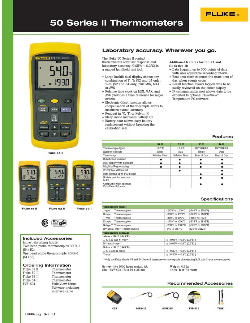
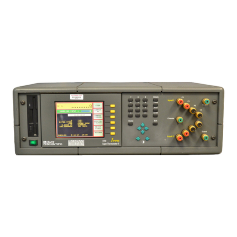
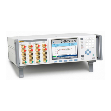
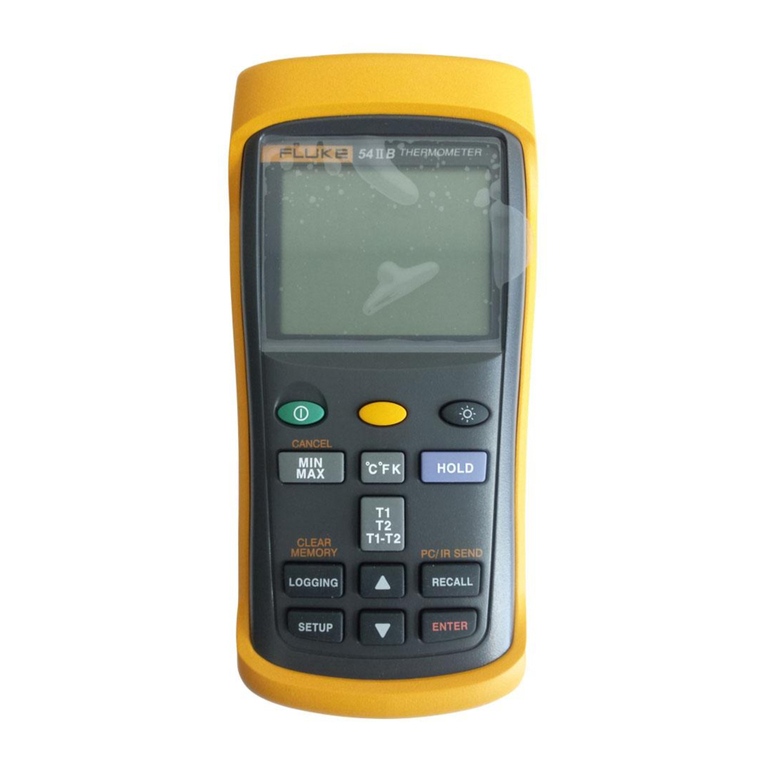
Fluke 2190A User manual

P/N 489229
June 1978
Rev. 1 6/79
2190A
Therm
Instruction Manual

The Fluke Corporation is pleased to hereby grant GIDEP
(Government-Industry Data Exchange Program) permission to reproduce the
manuals listed in the attachment. Permission is granted on the condition
that you legibly reproduce on the copies the legend "Reproduced With
Permission".
It is our understanding from your request dated January 23, 2001,
that the purpose for copying these manuals is to include them in the GIDEP
database, and that the material won't be copied for any other purpose.
Thank you for your cooperation, and for your interest in Fluke.
Sincerely,
Beverly A. Summers
Paralegal
Fluke Corporation
Intellectual Property Law Dept.
Direct: (425) 446-5770 [voice]
(425) 446-5117 [fax]
[email protected] [e-mail]

WARRANTY
Notwithstanding any provision of any agreement the following warranty is exclusive:
The JOHN FLUKE MFG. CO., INC., warrants each instrument it manufactures to be free from defects in material and
workmanship under normal use and service for the period of 1-year from date of purchase. Thiswarranty extends only
to the original purchaser. This warranty shall not apply to fuses, disposable batteries (rechargeable type batteriesare
warranted for go-days). or any product or parts which have been subject to misuse, neglect, accident, or abnormal
conditions of operations.
In the event of failure of a product covered by this warranty, John Fluke Mfg. Co., Inc., will repair and calibrate an
instrument returned to an authorized Service Facility within 1 year of the original purchase; provided the warrantor’s
examination discloses to its satisfaction that the product was defective. The warrantor may, at its option, replace the
product in lieu of repair. With regard to any instrument returned within 1 year of the original purchase, said repairs or
replacement will be made without charge. If the failure has been caused by misuse, neglect, accident, or abnormal
conditions of operations, repairs will be billed at a nominal cost. In such case, an estimate will be submitted before
work is started, if requested.
THE FOREGOING WARRANTY IS IN LIEU OF ALL OTHER WARRANTIES, EXPRESS OR IMPLIED,
INCLUDING BUT NOT LIMITED TO ANY IMPLIED WARRANTY OF MERCHANTABILITY, FITNESS,
OR ADEQUACY FOR ANY PARTICULAR PURPOSE OR USE. JOHN FLUKE MFG. CO., INC., SHALL
NOT BE LIABLE FOR ANY SPECIAL, INCIDENTAL, OR CONSEQUENTIAL DAMAGES, WHETHER IN
CONTRACT, TORT, OR OTHERWISE.
II any failure occurs, the following steps should be taken:
1. Notify the JOHN FLUKE MFG. CO., INC., or nearest Service facility, giving full details of the difficulty, and
include the model number, type number, and serial number. On receipt of this information, service data, or
shipping instructions will be forwarded to you.
2. On receipt of the shipping instructions, forward the instrument, transportation prepaid. Repairs will be
made at the Service Facility and the instrument returned, transportation prepaid.
SHIPPING TO MANUFACTURER FOR REPAIR OR ADJUSTMENT
All shipments of JOHN FLUKE MFG. CO., INC.. instruments should be madevia United Parcel Serviceor”BestWay”’
prepaid. The instrument should be shipped in the original packing carton; or if it IS not available, use any suitable
container that is rigid and of adequate size. If a substitute container is used, the instrument should bewrapped in paper
and surrounded with at least four inches of excelsior or similar shock-absorbing material.
CLAIM FOR DAMAGE IN SHIPMENT TO ORIGINAL PURCHASER
The instrument should be thoroughly inspected immediately upon original delivery to purchaser. All material in the
container should bechecked againsttheenclosed packing list. The manufacturerwill not be responsible for shortages
against the packing sheet unless notified immediately. If the instrument is damaged in anyway, aclaim should be filed
with the carrier immediately. (To obtain a quotation to reparr shipment damage, contact the nearest Fluke Technical
Center.) Final claim and negotiations with the carrier must be completed by the customer.
The JOHN FLUKE MFG. CO., INC, will be happy to answer all applications or use questions, which will enhance your
use of this instrument. Please address your requests or correspondence to: JOHN FLUKE MFG. CO., INC., P.O. BOX
C9090, EVERETT, WASHINGTON 98206, ATTN: Sales Dept. For European Customers: Fluke (Holland) B.V.. P.O. Box
5053, 5004 EB, Tilburg, The Netherlands.
*For European customers, Air Freight prepard.
John Fluke Mfg. Co., Inc., P.O. Box C9090, Everett, Washington 98206
Rev. 6181

Change/Errata Informal
Issue No:
4 2J79
This change/errata contains information necessary to ensure the accuracy of the following manual.
Enter the corrections in the manual if either one of the following conditions exist:
1. The instrument’s PCB revision letter is lower than that which is indicated at the beginnir
of the change/errata.
2. No revision letter is indicated at the beginning of the change/errata.
MANUAL
Title:
Print Date:
Rev and Date:
MODEL 2190A DIGITAL THERMOMETER
JUNE 1978
---
C/E PAGE EFFECTIVITY
Page No. Prlnt Date
1
1O/78
2 1O/78
3 10178
4 2179
5 2179
6 2179

2190A
.ERRATA #l
On page 4-2, replace Figure 4-l
and
Table 4-1 with the following:
Line Voltage Switch Settings
120 left
220 right
240 right
left
right
left
CHANGE #l-l 1690
Rev.-C, Main PCBAssembly
On page 5-10, make the following changes:
DELETE: S2-i/Switch/473454/89536/473454/ 1
CHANGE: Sl-l/Switch 473355 89536 473355
/483891/ /48389’i I
CHANGE #L-l 1732
Rev. -C, Main PCBAssembly, make the following changes:
On page 5-7:
ADD: Cl/Cap,mica,47 pF+5%, 500V/148536/71236/DM15E470J/1
On page 8-3, Figure 8-1, Al Main PCBAssembly make the indicated changes:
1O/78

2190A
ADD an arrow from 4 to scaleswitch:
0
On page 8-5, Figure 8-1, Al Main PCB Assembly, make the following changes:
TO: pf----3
’ bxq
CHANGE #3-l 1789
ERRATA#2
On page
l-2,
Table l-3 ( Specifications) make the following changes:
FROM: Common Mode Rejection Z 160 dB at .50,60 and 400 Hz +O.l% with 1OORunbalance at input.
TO: Common Mode Rejection Z 160 dB at dc, 50,60 and 400 Hz +O.l% with 1OOs2unbalance at input.
FROM: Normal Mode Rejection > 90 dB at 50,60 and 400 Hz *0.10/o
TO: Normal Mode Rejection > 90 dB at dc, 50,60 and 400 Hz +0.1%x
FROM: Power: 12V dc or 100, 200 or 240V ac *IO’% selectable, 50 to 400
HZ;
8W typical.
TO: Power: 12V dc or 100, 120,200 or 240V ac *lo%, selectable, 50 to 400 Hz; 8W typical.
On page 2-2, Figure 2-1, (Controls and Indicators) make the following changes:
On page 3-1, paragraph 3-S, line 9, change “microcomputed” to “microcomputer”.
IO/78
2

. 2190A
On page 3-3, paragraph 3-22, change line 4 to read:
“These voltages appear at FET switches Q12 and Q13 respectively.”
On page 3-3, Figure 3-2, change asshown below:
MEASUREMENT CYCLE = 300 ms
A
/ AUTO \
-, ZERO f I I
’ lmt0 ’ ,,,,TE- ’
i READ
i
AUTO ZERO COMMAND (Q5, QlO, 012, a161 OV i
200
ms 1 GRATE !
I I I
-15v : , I
I
I ‘+ I
I -1101 .O msl I
INTEGRATE COMMAND (Q15) ov , I I I r I
READ COMMAND, DE+ Qll) I
-15v I I I
I -hII+ , I
I
ov 1
i i 1 .O
ms
SETTLING TIME COMMAND n2 (Q8) I
-15v : u u u IJ
I
I I
I I I
COMPARE OUTPUT, CM TPl 01
INTEGRATOR OUTPUT U8-7)
BUFFER OUTPUT (TP7l
DE+ is generated for positive input voltages. Negative Input voltages enable the DE- mode which, in turn, operates FET
switch, Q13.
Waveform is shown for positive input voltage. It is inverted for negative inputs. Shown for full-scale in.
D
3 The Q numbers in parenthesis represent FET switches operated by the commands. See Figure 3-3.
Figure 3-2. Measurement Cycle Waveforms
On page 3-4, Figure 3-3, Simplified Schematic Analog Section, make the following changes:
ADD: Arrow to emitter; defines NPN.
1O/78
3

2190A
On page 4-2, paragraph 4-19, line 6, change to read asfollows:
“ . . . ambient temperature of 25 +2”C (77.0 ?3.6”F).”
On page 4-3, Table 4-2, change minimum use specifications for Mercury Thermometer asfollows:
FROM: “0.05”C resolution.”
TO: “0.05”F resolution.”
On page 4-3, paragraph 4-20, step 8, change to read asfollows:
“Select that portion of Table 4-3, , . .”
On page 4-4, paragraph 4-24, step 4, change to read asfollows:
“4. Select a switch setting of 9 (Cal), seeTable 2-2.”
On page 600-2, paragraph 600-12, delete the last sentence.
On page 602-3, paragraph 602-24, line 4, change “PRI” to “PTI”.
On page 606-3, Table 606-2, step 3, change “+4V” to “+.5V”.
On page 7A-1/7A-2, make the following changes:
Change line 7, of Introduction to read asfollows:
“ . . .
this manual with an X.”
Table on 7A-1/7A-2, ismissing title, at top of table, place the following title there:
“Table 7A-1. Manual
Status
and Backdating Information”
On Table 7A-1, change assembly name of the A3 Assembly to: “Thermocouple Input PCBAssembly”.
On page 3-4, Figure 3-3, change integrator capacitor:
FROM: Cl3
TO: C2.
ERRATA #3
On page 5-9, Table 5-2, Al Main PCB Assembly (cant), make the following changes:
FROM: R14/Res, var, lOOI,+-lo%, ~W/369520/89536/369520/1/1
TO: R14, Res, var 500k &lo%, ‘/W/474387/1 1236/360T503A/l
FROM: U3/1C, CMOS, Hex open drain buffers/473389/12040/MM74C906N/l/l
TO: U3/ SeeFinal Assembly.
ADD: XU3/Socket, IC, 14 pins/387138/71785/133-59-02-059/l
On page 5-3, Table 5-1, Final Assembly, make the following changes:
ADD: U3/IC, CMOS, Hex open drain buffers/473389/i 2040/MM74C906N/l /l
ERRATA +l
On page 602-3, Figure 602-l make the following changes:
ADD to the end of Step 5: the degree symbol (“““) is transmitted to the printer as a (“d”),
2179

2190A
ERRATA #5
On Page 600-2 replace paragraph 600-12 with the following:
600-I 2 The device is a preset 100 to I divider to provide the precision millivolt outputs
from a DC Calibrator required for calibration. The device wires into the thermo-
couple input PCB in place of the thermocouple probe during calibration. Refer
to the Y2022 instruction manual for schematic and additional informalion.
On Page 4-3, Paragraph 4-20 make the following changes:
Place the following note between steps 3 and 4:
On Page 4-6, paragraph 4-26, Step 6 make the following changes:
From: Adjust RI4 for a thermometer display of 10.0,. .
To : Adjust RI4 for a thermometer display of I .O,.
CHANGE #+l, 12061
Rev. E, A3 Thermocouple Input PCB Assembly.
On Page 5-13/5-14, Table 5-4 make the following changes:
Add: C3, C4/Cap. Ta. 1.O fiF +-20%, 7KV DC/t6lY 19/56289/196DlO5XOO35JAL/2
Add: UljlC, Linear/473819/04713/MC79LI2ACP/I
From: R2/Res, mtl film. 187K ?I%, 1/8W/291641/91637/CMF551873F/1
TO: RZ/Res, mtl film, 150K +I%‘, 1/8W/241083/91637/CMF551503F/l
CHANGE #?I, 12148
On Page 5-3, Table 5-l make the following changes:
From: F1-I 20/Fuse, Fast acting/ 196790/7 1400/AGC I-S/l /5/ 1
To: Fl-I?O/Fuse, Slo-blo. 1/8A/Ih648ti/7I400JMDL1-8/1/5/1
From: Fl-240/Fuse, Fast acting/109348/71400/AGCl-16!1/5/1
To: Fl-240/Fuse, Slo-blo, l/16A/l63030/7I400/MDLI -16/1/S/l
ERRATA #6
On Page 4-3 make the indicated changes to the steps of Paragraph 4-20 as shown below:
I. No change
2. No change
3. No change
4. No change
5. No change
6. No change
7. Select the temperature scale (C” or F”) on the 2190A to agree with the temperature
scale of the mercury thermometer in the lag bath.
2179

2190A
ERRATA #I%
(CONT)
8. Read the temperature of the mercury thermometer and find the corresponding mV reading
to this temperature (refer to either the NBS Monograph 125 or the DIN 43710 thermocouple
standard). Interpolation may be used as necessary.
9. Algebraically subtract the mV reading found in Step 8 from the first value found under the
“Divider Output MV” column of Table 4-3 for the thermocouple type in use.
10. Obtain a divider output equal to the result found in Step 9 by adjusting the calibrator and or
the Divider.
11. Verify that the 2190A reads the value listed in Table 4-3 within the limits specified.
12. Repeat steps 8. 9. 10 and I I for the remaining voltages in the “Divider Output mV” column
Table 4-3.
13. No change
14. No change
15. No change
16. No change
17. No change
6 2179

CEAIYGWEERATA
IlWOMATIO!J
ISSOB 110: 6 5/84
This change/errata contains information necessary to ensure the accuracy of
the following manual. Enter the corrections in the manual if either one of
the following conditions exist:
1.
The revision letter stamped on the indicated PCS is equal to or
higher than that given with each change.
2.
No revision letter is indicated at the beginning of the change/errata.
Title:
2190A
Print Date: June
1978
Rev.- Date:
l-6/79
C/E PAGEEFFECTIVITY
Page No. Print Date
1
:
4
:
7
8
9
10
11
12
9179
5180
5/80
5180
5180
5180
6/81
6/81
3182
3182
5/84
5/84

b
21901
CHANGE
tl - 12307
Rev.-E, A4 Output Option PCB Assembly (2180A-4020T)
On page 602-8:
FROM: R19;RES,VAR,lOO ~10%,1/2W1275735l11236136OTlOlA~l
TO: R191RES,VAR,CERMET,lOO ~10%,1/2W12851301895361285130~1
On page
602-10
and
8-10:
Rotate R19 90 degrees to face the outer edge of the PCB.
CHANGE f2
- 12414
Rev.- F,
A3
Thermocouple Input PCB Assy (21gOA-4003T)
On page 5-14:
FROM: C21CAP,MICA,lOO PF ~5$,500V11484941721361DM15FlOlJ~l
TO: C21CAP,MICA,150 PF ~5~,500V1148478172136~DM15F151J~1
On page 8-9:
Change value of C2, FROM: lOOpF, TO: 150pF
CHANGE t3 - 12526
On page
5-3:
In the Use Code Column place a
"1"
after the following
Reference Designators; H2, MPl, MP29 MP3, MP4, AND MP5.
Add the following note to the bottom of page 5-4.
1. If the handle on your case is secured by a rivet then these
components are included in one assembly (C-size Cover Assy).
Order John Fluke p/n:
516703.
CHANGE #4 -
12580
Rev.- G, A3 Thermocouple Input PCB Assembly (2190A-4003T)
Rev.- E, Al Thermometer PCB Assembly
(21
gOA-4001T)
On page 5-10:
FROM: R33lRES,COMP,22M
~5~,1/4W1221986101121lCB226511
TO: R33jRES,COMP,lOM
~5%,1/4W1194944101121
!CB1065/1
On page 8-3:
Change the value of R33, FROM: 22 M, TO:
10 M.
ERRATA
#l
On page 1-2, Table l-3:
ADD: PROTECTION CLASS 1 (Relates solely to insulation or grounding
properties further defined in IEC
348.)
ERRATA 12
On page 4-2, Table 4-1:
Change the position of S5 for the 240 volt selection,
FROM: Right, TO: Left.

2190A
CHANGE 55 -
12919
Rev.- 3,
A3
Thermocouple Input PCB Assy. (2190A-4003T)
Documentation Change, does not affect manual.
ERRATA t3 - 13515
On page
5-3,
under U4:
ADD: IC, UC, programmed for; J, K, T, C, & R152440518953615244051
Thermocouples.
(9004.1)
IAN UPDATED VERSION ON YOUR MICROCOMPUTER MAY BE I
IPRESENT IN YOUR INSTRUMENT. IF SO, YOUR INSTRUMENT :
!AT TURN ON WILL DISPLAY
"9004.1"
INSTEAD OF I
I "2190.1, 9005.1, 2, 3".
THE INFORMATION GIVEN IN:
iYOUR MANUAL IS CORRECT FOR BOTH, UNLESS YOU WISH TOI
lUSE THE -002 OPTION, IN WHICH CASE YOU MUST MAKE I
lTHE CHANGES AS 'DESCRIBED UNDER CHANGE f6 - 12964. :
i I
CHANGE C6 -
12964
Rev.- F, Output Option -002 PCB Assembly (2180A-4020T)
On page 602-7:
FROM: 00210utput Option -002 PCB Assemblyi-0021895361219OA-0021REF
Figure 602-2 (2180A-4020T)
TO: A4lOutput Option -002 PCB Assembly!-0021895361219OA-002iREF
Figure 602-2 (2180A-4020T)
A4Ali0.U. Adapter Assembly 1539288189536!539288!1
Add Table 602-6 and Figure
602-3
to the end of page 602-10:
I
I 1 Ql
I
I
I TRANSISTOR,SI,NPN I 218396
I
I 43
I TRANSISTOR,SI,NPN I 218396 I
ORES DEP CARJOK
+5$,1/4wI 348839 I
j j !: (IC,:-MO;,DUAL,"D;-TYPE
I 340117 I
I
1 U2 :IC,C-MOS,HEX,INVERTER
I 404681
I
I I-I I I
04713
04713
80031
02735
02735
I I
2N3904
I
2 I
2N3904 I REF I
CR251-l-5-lOKT!
1
1
CD4012AE I
1
I
CD4069BE I
1
I
I
I-

L
2190A
I
nnnnnnn
114
81
I
I
I
I
I
I
I
I
I
i
I
I
I
2180A
- 1621 I
Figure 602-i.
I
A4Al O.U. Adapter Assy.
602-11
On page 8-l:
ADD: 8-4.1 A4Al O.U. Adapter PCB Assy, 2180A-1021
8-13.1
ADD THE FOLLOWINGFIGURE BETWEENFIGURES 8-4 AND 8-5:
i
I
I
I
I
i
I
I
I
I
i
I
nnnnnnn
114
8
RI j
Q
Q3
I 2180A-1021, Rev. ---
21808-1621, Rev. ---
Figure 8-4.1 A4Al O.U. Adapter Assy.
5/80
3

2190A
CHANGE
17
- 12993
lTHE INFORMATION CONTAINED WITHIN THIS CHANGE SHOULD BE I
ICOMPLETED ONLY, IF AT TURN ON, YOUR INSTRUMENT DISPLAYS;:
1n9004.1w
or w9005.1n or "9005.2"
or "9005.3". I
I I
On page 2-4, para. 2-25, line
6:
FROM: . . . will display its model number, a decimal point, and the
type of microcomputer in use. Example: "2190.1" indicates type
1 microcomputer in use.
TO: . . . will display the microcomputer version, a decimal point,
and the type of microcomputer in use. Example: a display
reading of
H9004.1m
at turn on indicates that a type
1
of the
9004 version microcomputer is installed.
Replace the portion of Table 2-2 shown in the following Table 2-2:
Table 2-2 Thermocouple Input Module Switch Settings
I I
DISPLAY AT TURN ON I UC
I
i
TYPE SELECT SWITCH SETTING (Sl)
iTYPE I
-1
I I I 0 lll?jq14[5
6
' 7 I
8*1
90~1
I
9004.1,
or
9005.1 I 1
I J I K I T I I c I ; R I :CAL( CAL I
I or 9005.2 I 2 I J I K I I E I 1 S I R I lCALl CAL I
I or 9005.3 I
3
IJ**I K IT**1 i B f I R I iCAL; CAL ;
I I f-I- I-I- I-i- I-I- I I
-I--I
On page
5-3:
FROM: IC, UC, PROGRAMMED FOR; J, K, T, C, & R ; 473264!8953614732641
THERMOCOUPLES. (TYPE
-1)
TO: IC, UC, PROGRAMMED FOR; J,
K,
T, C, i R 1 53499018953615349901
THERMOCOUPLES. (TYPE
tl)
FROM: IC, UC, PROGRAMMED FOR; J,
K,
E, S, h R 1
47337118953614733711
THERMOCOUPLES. (TYPE -2)
TO: IC, UC, PROGRAMMED FOR; J, K, E, S, dr R :
52563418953615256341
THERMOCOUPLES. (TYPE P2)
On page 5-4:
FROM: IC, UC, PROGRAMMED FOR; J DIN, T DIN, I 504530189536~5045301
K, R, h B THERMOCOUPLES. (TYPE
-3)
TO: IC, UC, PROGRAMMED FOR; J DIN, T DIN, I 525642 189536 1525642 I
K, R, & B THERMOCOUPLES. (TYPE t3)
ERRATA t4
On page 602-4, step
10:
FROM:
10. Adjust
~26 for an output of 0
20.1 mV dc.
TO:
10.
Adjust R15 for an output of 0
~0.1 mV dc.
5/80 4

CHANGE
18
-
13287,
13409
Rev.- F, Al Main PCB Assembly (2190A-4001T)
On page
5-11:
ADD: VR4IDiode, Zener~18107310471311N969B11
On page 5-12 and 8-2:
Add VR4 and its symbol directly beneath and parallel to R49.
On page 8-3:
Add VR4 and its symbol between U14-10 and +15V (anode to Ul4-10).
On page 8-4:
Delete the connection between 55-16 (ANALOG COM) and 55-17 (RJ COM).
IALL 2190A MAIN PCBSWITH REV. LETTERS E AND LOWER 1
IARE m COMPATIBLEWITH THE FLUKE 2300A SCANNEROR (
/THE Y2001 THERMOCOUPLEMULTIPOINT SELECTOR. IF YOU ;
IHAVE SUCH AN INSTRUMENT AND YOU WISH TO INTERFACE !
IWITH THE
2300A
OR THE Y2001 You MUST CONTACTYOUR f
INEAREST FLUKE SERVICE CENTERFOR MODIFICATION. I
iHOWEVERIF YOUR2190A MAIN PCB HAS A REV. LETTER OFI
I F OR HIGHER THEN YOUR INSTRUMENT IS COMPATIBLE 1
IWITH THE 2300A OR THE
Y2001
AND NO MOD IS REQUIRED.;
I :
219OA
PCB Assy. (2180A-4020T)
3800141012951T1L1161311
536O45lO12951TIL1161311
380014101295~T1L116131REF
5360451012951TIL116131REF
380014lO1295~TlL116~31REF
5360451O12951TIL11613lREF
IC PWR/GNDchart for U22-4,
CHANGE#9 -
13540
Rev.- G, 002 output option
On page 602-g:
FROM: U210PTO-ISOLATOR
TO: U210PTO-ISOLATOR
FROM: U310PTO-ISOLATOR
TO: U310PTO-ISOLATOR
FROM: U410PTO-ISOLATOR
TO:
~41
0PT0-ISOLATOR
ERRATA 15
On page
8-13,
change the
FROM: GND, TO: GND ISOLATED .
On page 8-5, change S2 to
S3.
On page 4-5:
The celicius equivalent for 400 OF should be 204.4 'C,
M 240.0
'C, please change wherever applicable.
On page l-2, Table l-2:
FROM:
Y2026,
TO: Y2026B

2190A
On
page 2-l
add the following paragraph/procedure:
2-11
a When interfacing
your
2190A with a Fluke 23OOA Scanner, it
is
necessary to readjust the zero calibration of the
2190A.
Use the
following procedure
to accomplish this task.
1.
Turn the 21gOA and 23OOA power off.
2. Remove the Thermocouple Input Assembly from the rear of the
2190A and ensure that the input terminals are open.
3.
Place the
8
position (labled on the PCB) of Sl on and replace
the Thermocouple Input Assembly into the
2190A.
4. Remove a Thermocouple Scanner Card (Option -002) from the
23001b
Scanner,
short the input terminals for one of the channels
and replace the Thermocouple Scanner Card into the 23OOA.
5. Plug the 23OOA interface option cable into the 2190A
Accessory Connector on the rear
of
the 2190A.
6.
Turn the 2190A
and
23OOA
power on.
7.
Set the 23OOA to the channel which was shorted in step 4
above.
8.
Set the 23OOA channel delay to 0.0.
9. Adjust the 21908
zero
potentiometer (located on the 2190A
front panel, behind the screw-locked cover) to obtain a 2190A
display of 0.0.
10.
Turn
the 21908
and 23OOA power
off, remove the Thermocouple
Input
Assembly from
the 2190A, place all switches of
Sl
off
and
replace the Thermocouple Input Assembly into the 2190A.
NOTE
The 21908 zero will need to be readjusted if not
being used with the 23OOA. To readjust the 2190A
zero, turn the 2190A power
off,
remove
the
Thermocouple Input Assembly, short the input
terminals, repeat step
3
above, turn the 2190A power
on, and repeat step 9 above.
On page 602-3, para., 602-25, last sentence:
FROM: The message formats
are
shown In Figure 602-l.
TO: The message formats
are shown
in Figure 602-l and a timing
diagram is
given in
Figre 602-la.
5/80 6

219OA
On page 602-4, add figure 602.la as follows:
2190A DOU ASSEMBLY
TIMING DIAGRAM
I
Am?
(USER SUPPLIED)
t1
t2
t3
t4
t5
1 US max.
20
US tp 300 mS, depending upon reading cycle.
0 US min.
20 US min.
20 US typical
Figure 602-l a Timing Diagram
I
I
I
I
I
I
I
I
I
I
I
I
I
I
CHANGE510 - 14187
Rev.- G, Al Main PCB Assembly (21908-4001)
On
page
5-10:
CHANGE: R33!RES, COMP,
22M &5%,
1/4WZ?219861011211CB226511
TO: R331RES, COMP. 5.1M &5%, lw12g6467joll211CB515511
On page 8-3, in lower left quadrant:
Change the value of R33, FROM:
22M,
TO: 5.1M.
ERRATA16
On page 4-8, paragraph 4-41, line 6:
CHANGE: "be connected to the instrument."
TO: "or a 23OOA Scanner may be connected to the instrument."
Paragraph 4-41, step 1:
CHANGE: "Connect a Y2001 Multipoint Selector to the instrument."
TO: "Connect a Y2001 Multipoint Selector or a 23OOA Scanner to the
instrument.
6/81 7
-"l_-.---l-__ _.."

2190A
Paragraph 4-41, step 2:
CHANGE: Short the input to one channel on the Y2001 and select that
channel on the front panel.
TO: Short the input to one channel on the Y2001 or the 2300A Scanner
and select that channel on the front panel, If the 23OOA Scanner
is used, select a delay of 0.0.
Paragraph
4-41,
step 4:
CHANGE: Apply the output of the dc calibrator to TPl (LO) and TP18 (HI).
TO: Apply the output of the dc calibrator to TPl (HI) and TP18 (LO).
CHANGE
ill -
14299
Rev.- H, Al Main PCB Assembly (2190A-4001)
On page 5-11:
DELETE: XU31SOCKET, IC, 14.PIN1370304191506 1314.AG39D
I1
ERRATA
t7
On page 602-g:
CHANGE:
UlOlIC, C-MOS,
HEX 1NVERTERS~404681104713~MC1406BCP~1~1
TO:
UlOIIC, C-MOS,
HEX INVERTER1404681102735~CD4068BEf111
ERRATA
18
On page
1-3,
Table l-3. Specifications (cant):
CHANGE: "2190A Total Instrument Accuracy Specifications"
TO: "2190A Instrument Accuracy Specificationsn
ERRATA19
On page
4-3,
Table 4-2. Test Equipment Requirements:
Under minimum use specifications column change, FROM:
100 uV
resolution,
TO: Resolution:
100
uV.
Also under Resolution add the following: Accuracy:
.008%
In Figure 4-2, Equipment Connections add a voltmeter as showm below:
VOLTMETER
6/81 8

2190A
ERRATA #lO
On
page
602-4, replace Figure 602-l with the following:
Measurement Data Output Format for
R&232-C and Current Loop Ports
I I
I 11 21
31 41 51 61 71 81
9; 10: 11112i13 114 I 15~16~17118~1g120121~
lNORHAL TEMPERATUREMEASUREMENTDATA I
;cIilcRlsP(sPI* ISPlD ID ID ID/.ID/.ID IsP ISP IF/C~SP~SP;SP:SP~CRILF:
lOPEN THERMOCOUPLEOUTPUT (2190A only)
jCHICHjSPjSPI& ISPjD ID ID ;D/.ID/.ID 1SP ISP IF/CISP(SPIO IC lCRlLF\
IOVERRANGEOUTPUT I
(CHICHISP!SPI& ISPlD ID ID ID/.ID/.lD ISP ISP IF/CISPISPIO IL 1CRILFI
I I
! NOTE: If the limits option in the thermometer is I
I installed (option 27XOA-006) and is indicating I
i an out of limit condition, character slot 17 I
will be an exclamation point (I) for any of the!
I three above modes.
i SYXBOL DESCRIPTION
i CH I
Channel indent numbers (00 thru 99) I
I SP Space I
i: Thermometer limits Option Setpoint exceeded symbol I
I Plus or minus symbol I
I D Temperature data
values
(0 thru 9) I
I . Floating decimal point, will be in character slots
11
or I
I 12 or slot 12 when used with 2180A or 2190A Thermometer (
resp. I
IF/C Fahrenheit or Celsius I
I CR Carriage Return I
I LF Line Feed I
I ? Question mark
I OT Open Thermocouple (Character slots 16 and
17) I'
I OR
Over Range (Character slots 16 and
17)
I
I-----------------------------------------~------------------------- I
On page 602-2, para. 602-8 step 6 add the following:
When using the R&232-C interface, set the address switch
S3 to addres
1,
6, 7, 8 or 9. When using with the 2XXXA-522
Personality Card and the 1120A IEEE-488 Translator, set the
baud rate to 2400 and follow all discussions regarding the
R&232-C interface.
CHANGE512 - 15481
Rev.- J, A3 Thermocouple Input PCB Assembly
(2190-4003)
On page 5-14:
CHANGE: H21SCREW, SEMS, 4-40 X 3/81281196189536128119614
TO: H21SCREW, BRASS, 4-40 X
3/8I615716189536161571612
Other manuals for 2190A
1
Other Fluke Thermometer manuals

Fluke
Fluke 1504 User manual

Fluke
Fluke 65 User manual

Fluke
Fluke 5680 User manual

Fluke
Fluke COMARK P125W User manual

Fluke
Fluke 1551A Ex User manual

Fluke
Fluke CNX t3000 User manual

Fluke
Fluke 53 Instruction Manual

Fluke
Fluke 62 MAX User manual

Fluke
Fluke 54 Series II User manual

Fluke
Fluke 568 EX Installation instructions