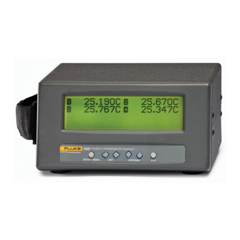
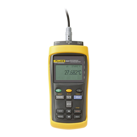
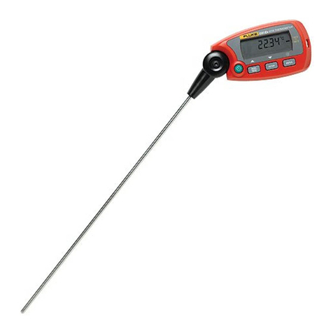
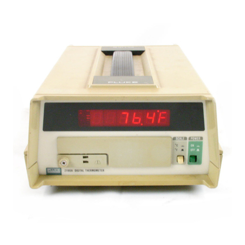
Fluke Hart Scientific 1523 Quick start guide

1523,1524
Reference Thermometer
Technical Guide
March 2014
© 2014 Fluke Corporation. All rights reserved.
All product names are trademarks of their respective companies.
www.calcert.com [email protected]1.800.544.2843 0
5
10
15
20
25
30
Rev11/99
LIMITED WARRANTY AND LIMITATION OF LIABILITY
Each Fluke product is warranted to be free from defects in material and workmanship under normal use and
service. The warranty period is one year and begins on the date of shipment. Parts, product repairs, and
services are warranted for 90 days. This warranty extends only to the original buyer or end-user customer of
a Fluke authorized reseller, and does not apply to fuses, disposable batteries, or to any product which, in
Fluke's opinion, has been misused, altered, neglected, contaminated, or damaged by accident or abnormal
conditions of operation or handling. Fluke warrants that software will operate substantially in accordance
with its functional specifications for 90 days and that it has been properly recorded on non-defective media.
Fluke does not warrant that software will be error free or operate without interruption.
Fluke authorized resellers shall extend this warranty on new and unused products to end-user customers
only but have no authority to extend a greater or different warranty on behalf of Fluke. Warranty support is
available only if product is purchased through a Fluke authorized sales outlet or Buyer has paid the
applicable international price. Fluke reserves the right to invoice Buyer for importation costs of
repair/replacement parts when product purchased in one country is submitted for repair in another country.
Fluke's warranty obligation is limited, at Fluke's option, to refund of the purchase price, free of charge repair,
or replacement of a defective product which is returned to a Fluke authorized service center within the
warranty period.
To obtain warranty service, contact your nearest Fluke authorized service center to obtain return
authorization information, then send the product to that service center, with a description of the difficulty,
postage and insurance prepaid (FOB Destination). Fluke assumes no risk for damage in transit. Following
warranty repair, the product will be returned to Buyer, transportation prepaid (FOB Destination). If Fluke
determines that failure was caused by neglect, misuse, contamination, alteration, accident, or abnormal
condition of operation or handling, including overvoltage failures caused by use outside the product’s
specified rating, or normal wear and tear of mechanical components, Fluke will provide an estimate of repair
costs and obtain authorization before commencing the work. Following repair, the product will be returned to
the Buyer transportation prepaid and the Buyer will be billed for the repair and return transportation charges
(FOB Shipping Point).
THIS WARRANTY IS BUYER'S SOLE AND EXCLUSIVE REMEDY AND IS IN LIEU OF ALL OTHER
WARRANTIES, EXPRESS OR IMPLIED, INCLUDING BUT NOT LIMITED TO ANY IMPLIED WARRANTY
OF MERCHANTABILITY OR FITNESS FOR A PARTICULAR PURPOSE. FLUKE SHALL NOT BE LIABLE
FOR ANY SPECIAL, INDIRECT, INCIDENTAL, OR CONSEQUENTIAL DAMAGES OR LOSSES,
INCLUDING LOSS OF DATA, ARISING FROM ANY CAUSE OR THEORY.
Since some countries or states do not allow limitation of the term of an implied warranty, or exclusion or
limitation of incidental or consequential damages, the limitations and exclusions of this warranty may not
apply to every buyer. If any provision of this Warranty is held invalid or unenforceable by a court or other
decision-maker of competent jurisdiction, such holding will not affect the validity or enforceability of any other
provision.
11/99
www.calcert.com [email protected]1.800.544.2843 0
5
10
15
20
25
30

iii
Table of Contents
1 Before You Start .......................................................................1
1.1 Introduction............................................................................................... 1
1.2 Standard Equipment................................................................................. 1
1.3 Safety Information ..................................................................................... 1
1.3.1 Warning .....................................................................................................1
1.3.2 Cautions ..........................................................................................................2
1.4 CE Comments........................................................................................... 3
1.4.1 EMC Directive .................................................................................................3
1.4.2 Immunity Testing .............................................................................................3
1.4.2.1 For Use As a Portable (Hand-held) Instrument ...................................................... 3
1.4.2.2 For Use As a Benchtop Instrument (AC Adapter).................................................. 4
1.4.3 Locking out non SI units..................................................................................4
1.5 Using Clamp-On Ferrites .......................................................................... 4
1.6 Emissions Testing ..................................................................................... 5
1.7 Low Voltage Directive (Safety).................................................................. 5
1.8 Authorized Service Centers ...................................................................... 5
2 Quick Start................................................................................7
2.1 Setup......................................................................................................... 7
2.2 Specifications ........................................................................................ 17
3 General Operation .................................................................23
3.1 Battery..................................................................................................... 23
3.2 DC Power Source ................................................................................... 23
3.3 Probe ...................................................................................................... 24
3.3.1 Internal or External reference junction compensation may be used with this
instrument. ................................................................................................................25
3.3.2 TC Internal Reference Junction.....................................................................25
3.3.3 TC External Reference Junction....................................................................25
3.4 Probe Lock Function............................................................................... 25
3.5 INFO-CON Connector............................................................................. 26
4 Display Functions and User Interface..................................29
4.1 Main Screen............................................................................................ 29
4.2 STATS...................................................................................................... 29
4.3 °C °F ....................................................................................................... 29
www.calcert.com [email protected]1.800.544.2843 0
5
10
15
20
25
30
1523, 1524 Reference Thermometer
iv
4.4 HOLD ...................................................................................................... 29
4.5 SETUP..................................................................................................... 30
4.5.1 Channel T1 ....................................................................................................30
4.5.1.1 Probe .................................................................................................................... 30
4.5.1.2 Config ................................................................................................................... 30
4.5.1.3 Base X .................................................................................................................. 30
4.5.1.4 Aux Displ ..............................................................................................................30
4.5.1.5 Temp Res.............................................................................................................. 31
4.5.1.6 RJ ......................................................................................................................... 31
4.5.2 Channel T2 (1524 Only) ................................................................................31
4.5.2.1 Probe .................................................................................................................... 32
4.5.2.2 Config ................................................................................................................... 32
4.5.2.3 Base X .................................................................................................................. 32
4.5.2.4 Aux Displ ..............................................................................................................32
4.5.2.5 Temp Res.............................................................................................................. 33
4.5.3 Instrument .....................................................................................................33
4.5.3.1 Fast Scan Mode ................................................................................................... 33
4.5.3.2 Contrast ................................................................................................................ 33
4.5.3.3 Auto-Off ................................................................................................................ 33
4.5.3.4 Backlight Time...................................................................................................... 33
4.5.3.5 Serial Port ............................................................................................................. 33
4.5.3.6 Baud Rate............................................................................................................. 34
4.5.3.7 Date/Time ............................................................................................................. 34
4.6 SAVE ....................................................................................................... 34
4.7 ARROWS, UP, DOWN ............................................................................. 34
4.8 ENTER..................................................................................................... 35
4.9 RECALL .................................................................................................. 35
4.9.1 Review Saved................................................................................................35
4.9.2 Send Saved...................................................................................................35
4.9.3 Delete Saved.................................................................................................35
4.9.4 Send Logs .....................................................................................................35
4.9.5 Delete Logs ...................................................................................................36
4.10 NEXT ....................................................................................................... 36
4.11 SHIFT ...................................................................................................... 36
4.12 RESET ..................................................................................................... 36
4.13 Ω mV ....................................................................................................... 36
4.14 TREND .................................................................................................... 36
4.15 LOG ........................................................................................................ 37
4.15.1 Free ...............................................................................................................37
4.15.2 Interval...........................................................................................................37
4.15.3 Tag.................................................................................................................38
www.calcert.com [email protected]1.800.544.2843 0
5
10
15
20
25
30
v
4.15.4 Session..........................................................................................................38
4.16 HOME ..................................................................................................... 38
5 LOGS .......................................................................................39
5.1 DEMAND LOG ........................................................................................ 39
5.2 AUTO-LOG ............................................................................................. 39
5.2.1 Auto-Log Operation.......................................................................................39
5.2.2 Sending Auto Log Data to a Computer.........................................................41
5.2.3 Data Upload Format......................................................................................41
5.2.4 Deleting Auto Log Data.................................................................................41
6 Digital Communication Interface..........................................43
6.1 Wiring...................................................................................................... 43
6.1.1 Setup .............................................................................................................44
6.1.2 Serial Operation ............................................................................................44
6.1.3 Data Upload Format .....................................................................................44
6.2 Command Syntax ................................................................................... 44
6.3 Serial Commands by Function or Group ................................................ 45
6.4 Serial Commands - Alphabetic Listing ................................................... 48
7 Calibration of Your Reference Thermometer Readout ........77
7.1 General ................................................................................................... 77
7.2 Introduction............................................................................................. 77
7.3 Terminology............................................................................................. 77
7.4 Fundamentals ......................................................................................... 77
7.5 Environmental Test Conditions................................................................ 77
7.6 Calibration Equipment ............................................................................ 77
7.7 Manual Calibration.................................................................................. 78
7.7.1 General..........................................................................................................78
7.7.2 As Found Data Procedure.............................................................................80
7.7.2.1 As Found Calibration Parameters ........................................................................ 80
7.7.2.2 As Found Data...................................................................................................... 80
7.7.3 Alignment Procedure.....................................................................................80
7.7.3.1 Alignment Test Data ............................................................................................. 80
7.7.3.2 Calculate New Adjustment Values ....................................................................... 80
7.7.4 As Left Data...................................................................................................80
7.8 Preparation for Reference Thermometer Calibration.............................. 80
7.8.1 Serial Communication ...................................................................................80
7.8.2 Cabling .........................................................................................................81
www.calcert.com [email protected]1.800.544.2843 0
5
10
15
20
25
30
1523, 1524 Reference Thermometer
vi
7.8.3 Scan Mode ....................................................................................................81
7.8.4 AC Adapter ...................................................................................................81
7.9 Manual Calibration Process.................................................................... 81
7.9.1 Procedure......................................................................................................82
7.9.1.1 Visual Inspection .................................................................................................. 82
7.9.1.2 1523/24 Calibration Parameters (As Found) ........................................................ 82
7.9.1.3 1523/24 Accuracy Test (As Found) ...................................................................... 84
7.9.2 1523/24 Alignment ........................................................................................89
7.9.2.1 L75_OHMS Range................................................................................................ 92
7.9.2.2 LO_OHMS Range................................................................................................. 92
7.9.2.3 MED_OHMS Range.............................................................................................. 92
7.9.2.4 HI_OHMS Range .................................................................................................. 92
7.9.2.5 Millivolt Range ...................................................................................................... 92
7.9.3 1523/24 As Left Test Data .............................................................................93
8 Troubleshooting .....................................................................95
9 Maintenance ...........................................................................97
Index...............................................................................................99
www.calcert.com [email protected]1.800.544.2843 0
5
10
15
20
25
30
vii
Figures
Figure 1 Locking out non SI units ...................................................................... 4
Figure 2 Clamp-On Ferrite ................................................................................. 5
Figure 3 Input/Output Connections - 1523 ........................................................ 7
Figure 4 Input/Output Connections - 1524 ........................................................ 8
Figure 5 Keys..................................................................................................... 9
Figure 6 1523 Menu......................................................................................... 11
Figure 7 1523 Menu (cont) .............................................................................. 11
Figure 8 1523 Menu (cont) .............................................................................. 12
Figure 9 1524 Menu......................................................................................... 14
Figure 10 1524 Menu (cont) ............................................................................ 14
Figure 11 1524 Menu (cont) ............................................................................ 15
Figure 12 1524 Menu (cont) ............................................................................ 16
Figure 13 1524 Menu (cont) ............................................................................ 17
Figure 14 1524 Menu (cont) ............................................................................ 17
Figure 15 12V DC Power source Polarity ........................................................ 24
Figure 16 Probe wiring diagrams..................................................................... 27
Figure 17 RS-232 wiring .................................................................................. 44
Figure 18 Flow chart for manual calibration .................................................... 79
www.calcert.com [email protected]1.800.544.2843 0
5
10
15
20
25
30
1523, 1524 Reference Thermometer
viii
Tables
Table 1 International Symbols............................................................................ 3
Table 2 1523 Input/Output Connections ............................................................ 7
Table 3 1524 Input/Output Connections ............................................................ 8
Table 4 1523 Key Functions............................................................................. 10
Table 5 1524 Key Functions............................................................................. 12
Table 6 General Specifications ....................................................................... 18
Table 7 Millivolt Measurement.......................................................................... 18
Table 8 Reference Junction Compensation..................................................... 18
Table 9 Ohms Measurement, RTDs ................................................................ 18
Table 10 Ohms Measurement, Thermistor ...................................................... 19
Table 11 Equivalent temperature accuracies derived from primary
specifications (Ω, mV) ............................................................................ 19
Table 12 Temperature, Thermocouples External Reference Junction............. 20
Table 13 Temperature, RTD Ranges
and Accuracies (RTD-90) ................................................................................ 21
Table 14 Temperature, Thermistor ................................................................... 21
Table 15 Fast Scan Mode Specifications ........................................................ 21
Table 16 Sample Interval per Channel in Seconds.......................................... 21
Table 17 Channel to Channel Differential Specifications ................................ 22
Table 18 Commands by Function or Group..................................................... 46
Table 19 Statistical Types ................................................................................ 73
Table 20 Probe Conversion Types ................................................................... 73
Table 21 Probe Characterization Parameters .................................................. 74
Table 22 Calibration Range Identifiers............................................................. 75
Table 23 Demand Log Statistical Types .......................................................... 76
Table 24 Error Messages ................................................................................. 76
Table 25 Test Equipment Specifications .......................................................... 78
Table 26 Standard Reference Resistor Specification ...................................... 78
Table 27 Standard Voltage Reference Specification ....................................... 78
Table 28 1523/24 Accuracy Test Settings and Specifications......................... 81
Table 29 1523/24 Accuracy Test Settings and Specifications – Voltage ......... 82
Table 30 As Found Readout/Calibration Parameter Settings .......................... 82
Table 31 1523/24 Alignment Settings .............................................................. 89
www.calcert.com [email protected]1.800.544.2843 0
5
10
15
20
25
30

1
Before You Start
Safety Information
1 Before You Start
1.1 Introduction
7KH5HIHUHQFH7KHUPRPHWHUVDUHGHVLJQHGWREHUHOLDEOHVWDEOHWHP
SHUDWXUHPHDVXULQJLQVWUXPHQWVWKDWFDQEHXVHGLQWKH¿HOGRUODERUDWRU\7KH\RIIHU
DFFXUDF\SRUWDELOLW\DQGVSHHGIRUQHDUO\HYHU\¿HOGFDOLEUDWLRQDSSOLFDWLRQ7KH
LQVWUXPHQWVKDYHEHHQGHVLJQHGZLWKWKH¿HOGXVHULQPLQGDQGDUHHDV\WRXVHZKLOH
PDLQWDLQLQJVWDELOLW\XQLIRUPLW\DQGDFFXUDF\FRPSDUDEOHWRVRPHODERUDWRU\LQVWUX
PHQWV<RXU)OXNHDQGWKHUPRPHWHUVDUHDKDQGKHOGEDWWHU\RSHUDWHG
LQVWUXPHQWWKDWPHDVXUHVWHPSHUDWXUHXVLQJ3ODWLQXPUHVLVWDQFH7KHUPRPHWHUV357
7KHUPLVWRUVDQG7KHUPRFRXSOHV7&
1.2 Standard Equipment
8QSDFNWKHLQVWUXPHQWFDUHIXOO\DQGLQVSHFWLWIRUDQ\GDPDJHWKDWPD\KDYHRFFXUUHG
GXULQJVKLSPHQW,IWKHUHLVVKLSSLQJGDPDJHQRWLI\WKHFDUULHULPPHGLDWHO\
9HULI\WKDWWKHIROORZLQJFRPSRQHQWVDUHSUHVHQW
● 5HIHUHQFH7KHUPRPHWHUZLWK$$EDWWHULHV
● $&$GDSWHUZLWKSRZHUFRUG
● 56&DEOH
● 8VHU¶V*XLGH
● 'RFXPHQWDWLRQ&'
● 5HSRUWRI&DOLEUDWLRQDQGFDOLEUDWLRQODEHO
● &ODPSRQIHUULWHV
,IDOOLWHPVDUHQRWSUHVHQWFRQWDFWDQ$XWKRUL]HG6HUYLFH&HQWHU6HH6HFWLRQ
$XWKRUL]HG6HUYLFH&HQWHUVRQSDJH
1.3 Safety Information
7KH5HIHUHQFH7KHUPRPHWHULVGHVLJQHGLQDFFRUGDQFHZLWK(1^QG(GL
WLRQ`DQG&$1&6$1R8VHWKLVLQVWUXPHQWRQO\DVVSHFL¿HGLQWKLV
PDQXDORWKHUZLVHWKHSURWHFWLRQSURYLGHGE\WKHLQVWUXPHQWPD\EHLPSDLUHG
$WarningLGHQWL¿HVFRQGLWLRQVDQGDFWLRQVWKDWSRVHKD]DUGVWRWKHXVHUDCaution
LGHQWL¿HVFRQGLWLRQVDQGDFWLRQVWKDWPD\GDPDJHWKHLQVWUXPHQWEHLQJXVHG
,QWHUQDWLRQDOV\PEROVXVHGRQWKHUHIHUHQFHWKHUPRPHWHUDQGLQWKLVPDQXDODUHH[
plained in 7DEOHRQSDJH
1.3.1 Warning
7RDYRLGSRVVLEOHHOHFWULFVKRFNRUSHUVRQDOLQMXU\
● 'RQRWXVHWKHUHIHUHQFHWKHUPRPHWHULQHQYLURQPHQWVRWKHUWKDQWKRVHOLVWHGLQ
WKHXVHU¶VJXLGH
www.calcert.com [email protected]1.800.544.2843 0
5
10
15
20
25
30
1523, 1524 Reference Thermometer
Safety Information
2
● 'RQRWXVHWKHUHIHUHQFHWKHUPRPHWHUIRUDQ\DSSOLFDWLRQRWKHUWKDQWKDWZKLFK
LVVSHFL¿HG7KHLQVWUXPHQWZDVGHVLJQHGIRUWHPSHUDWXUHPHDVXUHPHQWDQG
FDOLEUDWLRQ$Q\RWKHUXVHRIWKHLQVWUXPHQWPD\FDXVHXQNQRZQKD]DUGVWRWKH
XVHU
● ,IWKHUHIHUHQFHWKHUPRPHWHULVXVHGLQDPDQQHUQRWLQDFFRUGDQFHZLWKWKH
HTXLSPHQWGHVLJQWKHRSHUDWLRQDQGWKHSURWHFWLRQSURYLGHGE\WKHLQVWUXPHQW
PD\EHLPSDLUHG,QDGGLWLRQVDIHW\KD]DUGVPD\DULVH
● 'RQRWDSSO\PRUHWKDQWKHUDWHGYROWDJHDVPDUNHGRQWKHUHIHUHQFH
WKHUPRPHWHUEHWZHHQWKHLQSXWVRUEHWZHHQDQ\LQSXWDQGHDUWKJURXQG9
P$PD[DOOWHUPLQDOV
● )ROORZDOOHTXLSPHQWVDIHW\SURFHGXUHV
● &DOLEUDWLRQHTXLSPHQWVKRXOGRQO\EHXVHGE\WUDLQHGSHUVRQQHO
● 7KHUHIHUHQFHWKHUPRPHWHULVLQWHQGHGIRULQGRRUXVHRQO\
● %HIRUH\RXXVHWKHLQVWUXPHQWLQVSHFWWKHFDVH/RRNIRUFUDFNVRUPLVVLQJ
SODVWLF3D\SDUWLFXODUDWWHQWLRQWRWKHLQVXODWLRQVXUURXQGLQJWKHFRQQHFWRUV'R
QRWXVHWKHUHIHUHQFHWKHUPRPHWHULILWDSSHDUVGDPDJHGRURSHUDWHVDEQRUPDOO\
3URWHFWLRQPD\EHLPSDLUHG:KHQLQGRXEWKDYHWKHLQVWUXPHQWVHUYLFHG
● $OZD\VXVHDQLVRODWHG57'RU357PHWDOVKHDWKLVRODWHGIURPOHDGZLUHV
● 0DNHVXUHWKHEDWWHU\GRRULVFORVHGDQGODWFKHGEHIRUH\RXRSHUDWHWKH
UHIHUHQFHWKHUPRPHWHU
● 'RQRWRSHUDWHWKHUHIHUHQFHWKHUPRPHWHUDURXQGH[SORVLYHJDVYDSRURUGXVW
● )RUEDWWHU\RSHUDWLRQXVHRQO\$$EDWWHULHVSURSHUO\LQVWDOOHGLQWKHUHIHUHQFH
WKHUPRPHWHUFDVH
● 2QWKHPRGHOWKHUPRFRXSOHVFDQRQO\EHXVHGRQFKDQQHO
1.3.2 Cautions
7RDYRLGSRVVLEOHGDPDJHWRWKHUHIHUHQFHWKHUPRPHWHURUWRHTXLSPHQWXQGHUWHVW
● 'RQRWDSSO\PRUHWKDQWKHUDWHGYROWDJHDVPDUNHGRQWKHUHIHUHQFH
WKHUPRPHWHUEHWZHHQWKHLQSXWVRUEHWZHHQDQ\LQSXWDQGHDUWKJURXQG9
P$PD[DOOWHUPLQDOV
● 8QOHVVUHFDOLEUDWLQJWKHLQVWUXPHQW'2127FKDQJHWKHYDOXHVRIWKH
FDOLEUDWLRQFRQVWDQWVIURPWKHIDFWRU\VHWYDOXHV7KHFRUUHFWVHWWLQJRIWKHVH
SDUDPHWHUVLVLPSRUWDQWWRWKHVDIHW\DQGSURSHURSHUDWLRQRIWKHLQVWUXPHQW
● 7KHLQVWUXPHQWDQGDQ\WKHUPRPHWHUSUREHVXVHGZLWKLWDUHVHQVLWLYH
LQVWUXPHQWVWKDWFDQEHHDVLO\GDPDJHG$OZD\VKDQGOHWKHVHGHYLFHVZLWKFDUH
'2127DOORZWKHPWREHGURSSHGVWUXFNVWUHVVHGRURYHUKHDWHG
● '2127RSHUDWHWKLVLQVWUXPHQWLQDQH[FHVVLYHO\ZHWRLO\GXVW\RUGLUW\
HQYLURQPHQW
● 8VHWKHSURSHUSUREHVIXQFWLRQDQGUDQJHIRU\RXUPHDVXUHPHQW
● (QVXUHSUREHFRHI¿FLHQWVDUHGRZQORDGHG
www.calcert.com [email protected]1.800.544.2843 0
5
10
15
20
25
30
3
Before You Start
CE Comments
Table 1 International Symbols
Symbol Description Symbol Description
AC (Alternating Current) PE Ground
AC-DC Hot Surface (Burn Hazard)
Battery Read the User’s Guide (Important
Information)
Complies with European Union
directives Off
DC On
Double Insulated Canadian Standards Association
Electric Shock C-TICK Australian EMC mark
Fuse
The European Waste Electrical
and Electronic Equipment (WEEE)
Directive (2002/96/EC) mark.
1.4 CE Comments
1.4.1 EMC Directive
Fluke¶VHTXLSPHQWKDVEHHQWHVWHGWRPHHWWKH(XURSHDQ(OHFWURPDJQHWLF
&RPSDWLELOLW\'LUHFWLYH(0&'LUHFWLYH(&7KH'HFODUDWLRQRI&RQIRU
PLW\IRU\RXULQVWUXPHQWOLVWVWKHVSHFL¿FVWDQGDUGVWRZKLFKWKHXQLWZDVWHVWHG
7KHLQVWUXPHQWZDVGHVLJQHGVSHFL¿FDOO\DVDWHVWDQGPHDVXULQJGHYLFH&RPSOLDQFH
WRWKH(0&GLUHFWLYHLVWKURXJK(1(OHFWULFDOHTXLSPHQWIRUPHDVXUH
PHQWFRQWURODQGODERUDWRU\XVH±(0&UHTXLUHPHQWV
$VQRWHGLQWKH(1WKHLQVWUXPHQWFDQKDYHYDU\LQJFRQ¿JXUDWLRQV7KH
LQVWUXPHQWZDVWHVWHGLQDW\SLFDOFRQ¿JXUDWLRQZLWKVKLHOGHG56FDEOHV
1.4.2 Immunity Testing
1.4.2.1 For Use As a Portable (Hand-held) Instrument
7KHLQVWUXPHQWZDVWHVWHGWR%DVLF,PPXQLW\5HTXLUHPHQWVIRUSRUWDEOHWHVWDQGPHD
VXUHPHQWHTXLSPHQW
www.calcert.com [email protected]1.800.544.2843 0
5
10
15
20
25
30

1523, 1524 Reference Thermometer
Using Clamp-On Ferrites
4
1.4.2.2 For Use As a Benchtop Instrument (AC Adapter)
7KHLQVWUXPHQWZDVWHVWHGWR,PPXQLW\5HTXLUHPHQWVIRU&RQWUROOHG(0(QYLURQ
PHQWV8WLOL]HGLQWKLVVWDWHWKHLQVWUXPHQWLVGHVLJQHGWRRSHUDWHLQDFRQWUROOHG
HOHFWURPDJQHWLFHQYLURQPHQW7KHLQVWUXPHQWH[SHULHQFHVGHJUDGDWLRQLQWKHSUHVHQFH
RIVWURQJ¿HOGVLQWKHIUHTXHQF\UDQJHRIWR0+]DQGZHVXJJHVWWKDWLWQRWEH
XVHGLQFORVHSUR[LPLW\WR9+)WUDQVPLWWHUV
1.4.3 Locking out non SI units
7KURXJKDVSHFL¿FNH\SUHVVVHTXHQFHWKHXVHUFDQFKRRVHWRGLVDEOHWKH&)WRJJOH
VZLWFKVRWKDWWHPSHUDWXUHLVGLVSOD\HGLQ6,XQLWVRQO\2QFHWKHXQLWVWRJJOHVZLWFK
KDVEHHQORFNHGVXEVHTXHQWNH\SUHVVHVZLOOQRWDOORZWHPSHUDWXUHWREHGLVSOD\HGLQ
)
Instructions for locking out non SI units (see illustration below)
6LPXOWDQHRXVO\SUHVVDQGKROGGRZQWKH&)NH\DQGWKH%$&./,*+7NH\
SUHVVWKH32:(521NH\
7KHGLVSOD\ZLOOUHDGSI units only ON
5HOHDVHWKH&)DQGWKH%$&./,*+7NH\
7KH&)NH\ZLOOQRORQJHUWRJJOHEHWZHHQXQLWV
Figure 1
Press
Display reads: SI units only ON
°C °F
Press and hold +
°C °F
Release +
Locking out non SI units
5HSHDWLQJWKHVWHSVDERYHZLOOHQDEOHWKH&)WRJJOHVZLWFKDOORZLQJWHPSHUDWXUHWR
EHGLVSOD\HGLQ)7KHGLVSOD\ZLOOUHDGSI units only OFF
1.5 Using Clamp-On Ferrites
&ODPSRQIHUULWHVDUHSURYLGHGIRUXVHLQLPSURYLQJWKHLQVWUXPHQW¶VHOHFWURPDJQHWLF
(0LPPXQLW\LQHQYLURQPHQWVRIH[FHVVLYH(0LQWHUIHUHQFHOLNHDUHDVRIKHDY\
LQGXVWULDOHTXLSPHQW:HUHFRPPHQGSODFLQJWKHIHUULWHVRQWKHFDEOHVRISUREHVDW
WDFKHGWRWKHLQVWUXPHQW
7RDWWDFKDIHUULWHWRDSUREHFDEOHPDNHDORRSLQWKHFDEOHQHDUWKHFRQQHFWRUDQG
FODPSWKHIHUULWHDURXQGKDOIRIWKHORRSDVVKRZQLQWKHGLDJUDP7KHIHUULWHFDQEH
www.calcert.com [email protected]1.800.544.2843 0
5
10
15
20
25
30
5
Before You Start
Authorized Service Centers
HDVLO\GHWDFKHGDQGPRYHGWRDQHZSUREHZKHQQHHGHG6HH)LJXUHRQRSSRVLWH
SDJH
Figure 2
clamp-on ferrite
probe cable
Clamp-On Ferrite
1.6 Emissions Testing
7KHLQVWUXPHQWIXO¿OOVWKHOLPLWUHTXLUHPHQWVIRU&ODVV%
1.7 Low Voltage Directive (Safety)
,QRUGHUWRFRPSO\ZLWKWKH(XURSHDQ/RZ9ROWDJH'LUHFWLYH(&)OXNH
HTXLSPHQWKDVEHHQGHVLJQHGWRPHHWWKH(1
www.calcert.com [email protected]1.800.544.2843 0
5
10
15
20
25
30
7
Quick Start
Setup
2 Quick Start
2.1 Setup
Figure 3
RS232 12 V DC
30
V MAX
Input/Output Connections - 1523
Table 2 1523 Input/Output Connections
No. Name Description
1 Serial Serial interface connector
2 Connector, T1 Sensor Connector, Channel 1
4 Power External Power adapter connection
www.calcert.com [email protected]1.800.544.2843 0
5
10
15
20
25
30

1523, 1524 Reference Thermometer
Setup
8
Figure 4
RS232 12 V DC
30 V MAX
T1 T2
Input/Output Connections - 1524
Table 3 1524 Input/Output Connections
No Name Description
1 Serial Serial interface connector
2 Connector, T1 Sensor Connector, Channel 1
3 Connector, T2 Sensor Connector, Channel 2
4 Power External Power adapter connection
www.calcert.com [email protected]1.800.544.2843 0
5
10
15
20
25
30
1523, 1524 Reference Thermometer
Setup
10
Table 4 1523 Key Functions
No Key Description
1Power on or off
2Yellow Second or Special Function Key
3Turns the backlight on or off
4STATS 1st Press: MAX, 2nd Press: MIn, 3rd Press: AVE, 4th Press: STD DEV
5°C °FUnits, °C/°F
6HOLD 1st press - Holds value on screen "-- HOLD --" across bottom of screen. 2nd press -
Releases Screen hold.
7SETUP Enters setup menu, see menu structure
8SAVE Saves measurement as a logged data point
9Arrows increment or decrement selections in an active eld. In Graph Mode, Arrows change
the scale of the graph.
10 ENTER Selects highlighted selection, Saves a new selection.
11 RECALL 1st Press - Enters Recall menu, 2nd Press - Exits Recall Menu
12 NEXT Moves down to next option on screen.
13
+
STATS “RESET” - Resets Stats Data
14
+
°C °F“ΩmV” - Toggles from °C to Ωor Ωto °C (PRT, thermistor), °C to mV or mV to °C (TC)
15
+
HOLD “TREND” - Starts Graphing data
16
+
ENTER “HOME” Returns user to main screen
www.calcert.com [email protected]1.800.544.2843 0
5
10
15
20
25
30

11
Quick Start
Setup
Figure 6 1523 Menu
Figure 7 1523 Menu (cont)
www.calcert.com [email protected]1.800.544.2843 0
5
10
15
20
25
30

Figure 8 1523 Menu (cont)
Table 5 1524 Key Functions
No Key Description
1Power on or off
2Yellow Second or Special Function Key
3Turns the backlight on or off
4STATS 1st Press: Max, 2nd Press: Min, 3rd Press: Ave, 4th Press: STD DEV
5°C °FUnits, °C/°F
6HOLD 1st press - Holds value on screen "-- HOLD --" across bottom of screen. 2nd press -
Releases Screen hold.
7SETUP Enters setup menu, see menu structure
8SAVE Saves measurement as a logged data point
www.calcert.com [email protected]1.800.544.2843 0
5
10
15
20
25
30

13
Quick Start
Setup
No Key Description
9Arrows increment or decrement selections in an active eld. In Graph Mode, Arrows
change the scale of the graph.
10 ENTER Selects highlighted selection, Saves a new selection.
11 RECALL 1st press - Enters Recall Menu, 2nd press - Exits Recall Menu
12 NEXT Moves down to next option on screen.
13
+
STATS “RESET” - Resets Stats Data
14
+
°C °F“ΩmV” - Toggles from °C to Ωor Ωto °C (PRT, thermistor), °C to mV or mV to °C (TC)
15
+
HOLD “TREND” - Starts Graphing data
16
+
SAVE “LOG” - Log a series of measurements, see Auto Log in menu structure
17
+
ENTER “HOME” Returns user to main screen
www.calcert.com [email protected]1.800.544.2843 0
5
10
15
20
25
30
Other manuals for Hart Scientific 1523
4
This manual suits for next models
5
Table of contents
Other Fluke Thermometer manuals