Flux FMT 50 PP User manual

Operating manual
with spare parts list
Liquid Meter FMT 50 PP
Contents
1. Product description 2
2. Safety instructions 2
3. Technical Description 4
4. Operation 4
5. Fault monitoring 5
6. Meter programming 5
7. Spare parts construction and spare parts list 6
8. Dimensional Drawing 7
9. Chart of pressure loss 8
10. Features 8
11. Declaration of Conformity 9

- 2 -
1. Product description
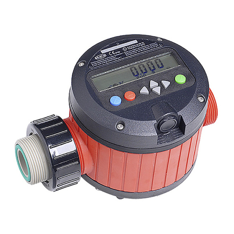
The FMT 50 is a flow meter for flowing liquids based on the measuring principle of a turbine wheel
meter. It can be used as a fixed meter or as a manual flow meter. The optional pulse generator
allows it to be used in a fluid management system.
The FMT 50 must not be operated with flammable and explosive liquids from hazard
material classes AI, AII and B. Liquids of hazardous material class A III must not be
used, if they are heated above their flash point.
The FMT 50 turbine wheel meter consists of a measurement chamber with a turbine wheel and a
cover containing the evaluation electronic system as well as display and keyboard. The turbine
wheel has a magnet pair which in the case of volume flow transfers the meter pulses to a reed
switch on the evaluation electronic system.
2. Safety instructions
The device is a state of the art piece of equipment and has been constructed according to recognised safety
specifications. It is nevertheless possible that use of the device will present hazards to the operator or to third parties, or
may damage the device or other property. It is therefore essential to act in accordance with these operating instructions,
and in particular with those sections identified as warnings.
Warnings and symbols
In the operating instructions, the following signs are used for highlighting important information.
Special information regarding the economic use of the device/machine.
Special information or "do’s and don’ts" for damage prevention.
Information or "do’s and don'ts" for the prevention of damage to persons or equipment.

- 3 -
Appropriate use
The device may only be used if it is in perfect condition, and then only for its intended purpose, in compliance
with all safety regulations, with an awareness of the potential risks, and according to the operating
instructions. Any faults that may impair the safety must be rectified immediately.
The system and its components are only to be used for handling the liquids listed and the purpose described.
Using the machine for any other purpose would constitute inappropriate use. The manufacturer is not responsible
for any damages arising as a result of this, the risk for this is borne only by the operator.
In the event of the measuring medium being contaminated by particles >150 µ, it is vital that suitable filters are
used. If not the flow meter could become clogged and impaired in its operability.
When used in the urea range (AUS32), the urea solution must be in accordance with DIN 70070.
Organisational measures
These operating instructions should always be kept readily available at the site of operation! Each person
concerned with the assembly, commissioning, maintenance and operation of the equipment must have read
and understood the entire manual. It is essential that the type plate and the warnings attached to the device
are observed, and are maintained in a fully readable condition.
Qualified Personnel
The operating, servicing and assembly personnel must be appropriately qualified for their work. The areas of
responsibility, the accountability and the supervision of the personnel must be precisely determined by the
operator. If the personnel do not have the required knowledge, they must be trained and instructed. The
operator must also ensure that the contents of the operating instructions are properly understood by the
personnel.
Water Protection
The device has been designed to handle materials that are hazardous to water. The regulations (e.g. WHG,
VawS) applying to the site of operation are to be observed.
Servicing and Maintenance
According to the statutory regulations only specialist contractors are to be entrusted with work on systems for
liquids that are harmful to water. No alterations, extensions, or conversions of the device with potential impact
upon safety are permitted without prior consent of the manufacturer. Spare parts must comply with the technical
requirements specified by the manufacturer. This is always assured if original spare parts are used.
Except for battery changing, only the manufacturer is to undertake manipulations of whatever kind on the flow
meter.
Electric power
Work on the electrical equipment of the device may only be carried out by a qualified electrician or by trained
persons under the guidance and supervision of a qualified electrician according to electro technical guidelines.
Machine or system parts, on which inspection, maintenance or repair work is to be carried out, must be
de-energised.
Hydraulics
Only persons with special knowledge and experience with hydraulic systems may carry out work on hydraulic
parts and equipment. All lines, hoses and screw joints should regularly be checked for leaks and external
damage. Any damage must be rectified immediately. Any oil spurting out can cause injuries and fire. The relevant
safety regulations must be followed when handling oils, greases or other chemical substances!

- 4 -
3. Technical Description
3.1 Display
LC display with five-digit volume indicator with 16 mm high digits and display of the litre
measurement unit (optional US-Gal, UK-Gal) and low battery capacity display.
The minimum digital step of the measured value is 0.02 litre and that of the non-resettable
totalisers 1 litre.
3.2 Keyboard
Membrane keyboard with 2 keys: „Total“, „Reset“ and „Mode“.
3.3 Battery
Lithium battery (Type CR ½ AA, 3.6V, 1200 mAh) with a minimum operating life of approx.
10 years given a 1,000,000 litre flow rate during this period.
The battery can be replaced once the housing is opened. Cumulative and calibration values
are not affected by replacement.
3.4 Acquisition of values
Logging the measurement chamber pulse signal.
Fault-redundant storage and read-out of measurement unit and calibrating factor.
4. Operation
4.1 Delivery state
On delivery the meter is provided with the factory "litre" measurement unit and the "1,000"
calibrating factor. Pre-tested meters have a calibrating factor already factory-adjusted.
Alternatively this adjustment can be undertaken at a later date. The meter as it is can meter
deliveries.
4.2 Basic state, flow measurement
In the basic state the LC display indicates the metered volume since the last reset. The display
has three digits before the decimal point and two after; 0.01 litres is the minimum digital step.
The "litre" measurement unit (optional US-Gal, UK-Gal) is shown on the lower line.
The keys are blocked when metering takes place.
4.3 Reset – "Reset" key
On pressing the "Reset" key, the programme status is shown for as long as the key remains
pressed. On releasing the key, all the segments are tested one after the other followed by
volume meter resetting. Should pulse signals proceed (volume flow) during the above, then the
display test is interrupted and changed to the basic state.
4.4 Totaliser – Key „Total“
On pressing the "Total" key, the totaliser status is shown for as long as the key remains
pressed. The display is rounded in litres (optional US-Gal, UK-Gal). Should pulse signals
proceed (volume flow) during the display, then the totaliser status display is interrupted and
changed to the basic state.
4.5 Calibrating factor display – Keys „Total“ + „Reset“
When the "Reset" key is pressed in addition to the pressed "Total" key (totaliser status display),
the set calibrating factor is displayed for as long as the two keys are pressed. The calibrating
factor can be between 0.500 and 1.500.
Should pulse signals proceed (volume flow) during the display, then the calibrating factor
display is interrupted and changed to the basic state.

- 5 -
5. Fault monitoring
5.1 Battery symbol display in the basic state
The built-in 3.6 V lithium battery, type CR ½ AA, is designed for a minimum operating life of
approx. 10 years given a 1,000,000 litre flow rate during this period. The appearance of the
battery symbol in the basic state indicates that the battery capacity is exhausted and that the
battery must be replaced within the next 6 months. The times may be reduced given extreme
operating conditions such as a high flow rate or very low temperatures!
The battery can be replaced without tools once the housing is opened. Cumulative and
calibration values are not affected by replacement.
5.2 Display of five dashes „-----“
The fact of the meter stopping operations and the appearance of five horizontal dashes in the
display points to a fault in the evaluation electronics. As a result, the meter must be replaced.
6. Meter programming
The measurement unit (litre, US-Gal, UK-Gal) and the calibrating factor (0.500 - 1.500) can be
set and stored in a fault-redundant manner.
Before a new calibrating factor can be established, a delivery must be made into a
satisfactorily accurate vessel or undertaken by means of a reference meter. The new
calibrating factor is calculated as follows:
shown
delivered
existingnew
Volume
Volume
FactorFactor ×=
Example: A 2 litre measurement vessel is filled; the meter only indicates 1.90 litres. The
existing calibrating factor is 1.040.
The new calibrating factor is calculated to:
090.1
90
.
1
00.2
040.1 =×
(rounded)
Attention: No volume pulses are counted when the meter is in the programming mode. When
no key is pressed for over 5 minutes in the programming mode, the meter automatically
returns to the basic state.
6.1 Changing over into the programming mode
In order to get into the programming mode, the "Mode" key is to be pressed for approximately
5 seconds. Then all segments rapidly flash (approx. 3 Hz) on the LC display.
6.2 Setting the measurement unit
After releasing the "Mode" key, the measurement unit set appears in the display. Renewed
pressing of the „Total“ key results in the measurement unit switching between „Litre“, „US-Gal“
and „UK-Gal“. Renewed pressing of the "Mode" key and the set measurement unit is taken on.
Attention: Any change to the measurement unit causes the volume indicator and totaliser to be
reset.

- 6 -
6.3 Setting the calibrating factor
After pressing the "Mode" key, the calibrating factor set appears in the display. Pressing the
"Total" key results in the calibrating factor being counted up in 0.010 steps and pressing the
„Reset“ key in it being counted down accordingly.
Press the "Mode" key and the set calibrating factor is taken on.
6.4 Resetting all settings (initialisation)
The effect of pressing and holding the "Total" and "Reset" keys at the same time when setting
the measurement unit or calibrating factor is to delete all the meter values and carry out an
initialisation.
Following values are initialised:
Measurement unit: Litre
Calibrating factor: 1.000
Delivery quantity: 0.00 litres
Totaliser: 0 litres
6.5 Ending the programming mode
In order to end the programming mode, the "Mode" key is again to be pressed after setting the
calibrating factor. The meter then reverts to the basic state. When no key is pressed for over
5 minutes in the programming mode, the meter automatically returns to the basic state.

- 7 -
7. Spare parts construction and spare parts list
Spare parts list
Pos. Description PP
10 Cover complete. + Battery A05 00 001
20 Measuring chamber + typeplate A05 00 002
30 Battery 940 04 033
40 Four cylinder head screws DIN 912 - M 4x45, A2 900 65 016

- 8 -
8. Dimensional drawing
9. Chart of pressure loss
0,0
0,5
1,0
1,5
0 10 20 30 40 50 60 70 80 90 100 110 120
Volumenstrom [L/min]
D
r
u
c
k
v
e
r
l
u
s
t
[
b
a
r
]
10. Features
Volume flow range 5 – 50 l/min
Viscosity range 0.8 – 40 mPa s
Operating pressure 4 bar
Burst pressure 9 bar
Accuracy uncalibrated ± 2%
Accuracy calibrated ± 1%
Repeat accuracy ± 0.5 %
Nominal width 1“ External thread
Protection category IP 65
Battery Li-MO, Type CR ½ AA, 3,6 V, 1200 mAh, exchangeable
Pulser output: optional, 25 Pulses/litre
Temperature range Operation: -10°C - +50°C
Storage: -20°C - +70°C
Dimensions approx. 90 x 130 x 61 mm
Weight approx. 0,3 kg

- 9 -
11. Declaration of Conformity
EG-Konformitätserklärung
EC Declaration of Conformity
Déclaration de Conformité CE
Hiermit erklären wir, dass die Bauart des FLUX Flüssigkeits-Mengenmessers FMT 50 in den verschiedenen
Werkstoffen und Bauarten in der gelieferten Ausführung den folgenden einschlägigen Bestimmungen entspricht:
We herewith confirm that the construction of the FLUX Liquid Meter FMT 50 in different materials and versions
corresponds to the following EC-rules:
Nous confirmons que la construction du Compteur de Débit FLUX FMT 50 de matériaux et versions différents est
conforme aux dispositions règlementaires suivantes:
(1) EG-Richtlinie Maschinen EC Machinery Directive Directive CE Machines
98/37/EG 98/37/EC 98/37/CE
(2) EG-Richtlinie EMV EC Electromagnetic Directive CE Comptabilité
2004/108/EG Compatibility Directive Electromagnétique d’Appareils
2004/108/EC 2004/108/CE
(3) EG-Niederspannungsrichtlinie EC Low Voltage Directive Directive CE Bas Voltages
2006/95/EG 2006/95/EC 2006/95/CE
Angewendete harmonisierte Normen:
Applied harmonised standards:
Normes appliquées harmonisées
DIN EN 55014 DIN VDE 0843 T1
Maulbronn, 01.07.2008
FLUX-GERÄTE GMBH
Klaus Hahn
Geschäftsführer

- 10 -
Talweg 12 75433 Maulbronn
Telefon: 07043 101-0 Telefax: 07043 101-444
Fax International: + 49 7043 101-555
Table of contents
Other Flux Measuring Instrument manuals