● RM 32-bit Cortex MCU, frequency up to 64 M HZ, 25% higher than the previous generation of M CU.
● PW M frequency up to 128k, high frequency for higher throttle makes running smoother.
● ES C firmware is optimized, makes the throttle linearity smoother and the response faster.
● Supports regular 1-2ms pulse width input, as well as Oneshot125 (125-250us), Oneshot42 (41.7-83.3us) and
Multshot (5- 25us). The input signal is automatically detected by the ESC upon power up.
● All Dshot and Proshot signals are supported .
● Damped light does regenerative braking, causing very fast motor retardation, and inherently also does active
freewheeling.
● Small size and light weight, support higher KV motor and more power load .
● The output of the modular BEC can supply power to the receiver, steering gear and other external devices,
which makes the application of the E SC more extensive;.
● Adjustable B EC output 5V / 3A or 12V / 2A , more flexible application.
Thank you for using our product. Any Improper operation may cause personal injury or damage to the
product and related equipments. This high power system for RC model can be dangerous ,we strongly
recommend reading the user manual carefully and completely. We will not assume any responsibility for any
losses caused by unauthorized modifications to our product. We have the right to change the design,
appearance, performance and usage requirements of the product unannounced.
Brushless ESC
User Manual
*All pictures are for reference only
*Please ensure all solder joints are insulated with heat shrink where necessary.
Programming parameters below can be accessed from the configuration software (B LHeliSuite32).
01 Main features
ATTENTION
●Firmware:Flycolor_Raptor_5.
●The supported working voltage is 3-6s liPo when 5V / 3A B EC is selected, it is 4-6s liPo when 12V / 2A BE C is selected .
02 Specifications
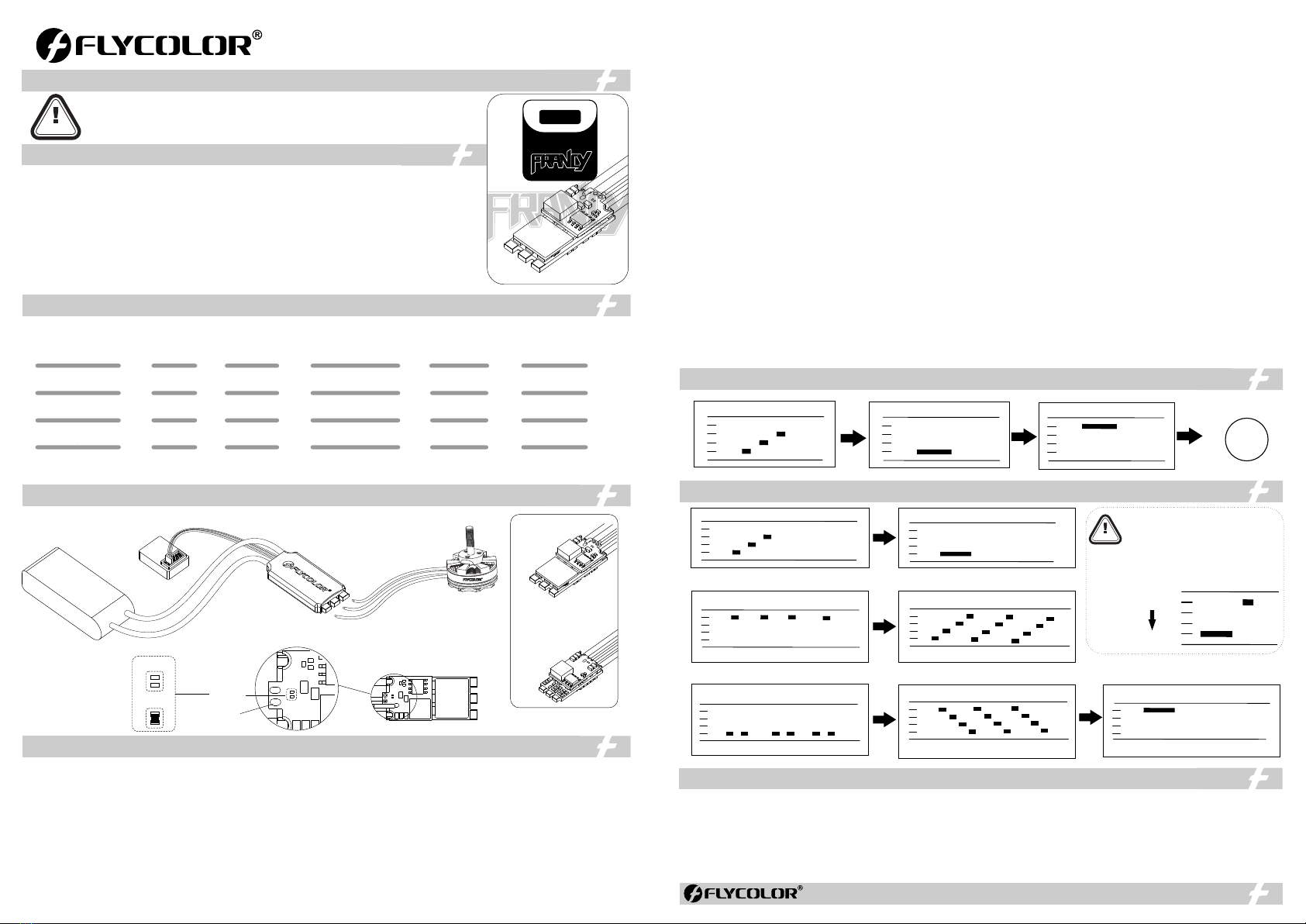
03 Wiring diagram
04 Programming parameter
www.flycolor.net 251400-1160, V1.1
*All pictures are for reference only
BEC / LiPo
Burst Current
(10S,Good H.D. )
Size
(For reference)
Weight
(For reference)
Con. Current
(Good H.D. )
Model
A·40A50
30A·20A
Francy 2 series
NC=5V
SC=12V
Default
NC=5V
5V-12V Output
2
B L 3 2-
2
25A 12.5g 29x14x9mm
Francy 2-20A 20A
50A 16.5g
5 V , 3 A / 3 - 6 S
1 2 V, 2 A /4 - 6 S
33x16x10mm
Francy 2-40A 40A
60A 16.5g 33x16x10mm
Francy 2-50A 50A
35A 12.5g 29x14x9mm
Francy 2-30A 30A
5 V , 3 A / 3 - 6 S
1 2 V, 2 A /4 - 6 S
5 V , 3 A / 3 - 6 S
1 2 V, 2 A /4 - 6 S
5 V , 3 A / 3 - 6 S
1 2 V, 2 A /4 - 6 S
Motor
Battery
Receiver
ESC
2.Throttle signal detected
(arming sequence start):
1. Power up:
Once Once
1.Power up: 2.Throttle signal detected
(arming sequence start):
Once
3.When throttle is above midstick
(measuring max throttle):
4.If throttle is above midstick for 3 seconds:
This beep sequence indicates that max
throttle has been stored
Once
While
measuring
5.When throttle is below midstick
(measuring min throttle):
While
measuring
6.If throttle is below midstick for 3 seconds:
This beep sequence indicates that min
throttle has been stored.
Once
Complete
7.Throttle calibration is complete.
After this, the motor will run.
Once
Example:
Highest tone
Lowest tone
1.Throttle calibration will be more simple
if using Flight Controller Configurator.
2.When the input signal is Dshot, throttle
calibration is disabled, and the throttle
calibration values are ignored.
OK
3.Zero throttle detected
(arming sequence end):
Once
4.After this, the
motor will run.
Short beep
Long beep
05 Beeps-Normal operation
06 Beeps - Throttle calibration
ATTENTION
1. Rampup power: Rampup power can be set to relative values from 3% to 150%. This is the maximum power that is allowed when ramping up at low rpms and
during startup. For low rpms, the maximum power to the motor is limited, in order to facilitate detection of low BEMF voltages.
Rampup power also affects bidirectional operation, as the parameter is used to limit the power applied during direction reversal.
During startup, the actual applied power depends on throttle input, and can be lower than the maximum level set by the rampup power parameter, but the
minimum level is a quarter of the maximum level.
2. Motor timing: Motor timing can be set between approximately 1° and approximately 31° in approximately 1° increments (actual accurate values here are
15/16ths of a degree). Typically a medium setting will work fine, but if the motor stutters it can be beneficial to increase timing. Some motors with high inductance
can have a very long commutation demagnetization time. This can result in motor stop or stutter upon quick throttle increase, particularly when running at a low
rpm. Setting timing to high will allow more time for demagnetization, and often helps. Motor timing can also be set to auto.
3. PWM frequency: Motor pwm frequency can be programmed in a range. Support variable pwm frequency where the pwm frequency is controlled by motor RPM.
-Low frequency for low throttle gives good active braking where it is most needed. -High frequency for higher throttle makes running smoother
4. Demag compensation: It is a feature to protect from motor stalls caused by long winding demagnetization time after commutation. The typical symptom is
motor stop or stutter upon quick throttle increase, particularly when running at a low rpm. As mentioned above, setting high commutation timing normally helps,
but at the cost of efficiency. Generally, a higher value of the compensation parameter gives better protection. If demag compensation is set too high, maximum
power can be somewhat reduced.
5. Sine Modulation Mode:
Sine modulation mode can give a few percent more efficient running &smoother running. Note: if sine mode is chosen, then variable pwm frequency is disabled.
6. Maximum Acceleration: Maximum acceleration can be set between 0.1%/ms and 25.5%/ms. It can also be set to maximum, in which case acceleration is not
limited. Limiting acceleration is primarily intended as a backup parameter that can be used in cases where too hard acceleration gives desyncs. When setting to
e.g. 10%/ms, it means that the power applied to the motor is not allowed to increase by more than 10% per millisecond.
7. Motor Direction: Motor direction can be set to fwd/rev/bidirectional 3D/bidirectional 3D rev/bidirectional soft and bidirectional soft rev. In bidirectional mode,
center throttle is zero and above is fwd rotation and below is reverse rotation. When bidirectional operation is selected, throttle calibration is disabled.
8. Startup Beep Volume: Sets the volume of beeps during power up.
9. Beacon/Signal Volume: Sets the volume of beeps when beeping beacon beeps. The ESC will start beeping beacon beeps if the throttle signal has been zero
for a given time. Note that setting a high beacon strength can cause hot motors or ESCs!
10. Beacon delay: Beacon delay sets the delay before beacon beeping starts.
11.Throttle Cal Enable: If disabled, throttle calibration is disabled.
12. Min throttle, max throttle and center throttle:
These settings set the throttle range of the ESC. Center throttle is only used for bidirectional operation. The values given for these settings are for a normal
1000us to 2000us input signal, and for the other input signals, the values must be scaled. For Dshot input signal, these settings have no effect.
13.Temperature protection:
Temperature protection can be enabled or disabled. And the temperature threshold can be programmed The programmable threshold is primarily meant as a
support for hardware manufacturers to use, as different hardwares can have different tolerances on the max temperatures of the various components used.
14.Low RP M power protect: It can be enabled,disabled or on adaptive. Disabling it can be necessary in order to achieve full power on some low kV motors
running on a low supply voltage. However, disabling it increases the risk of sync loss, with the possibility of toasting motor or E S C.
15.Low Voltage Protection: It can be set between 2.5V and 4.0V per lipo cell. Or it can be disabled. When enabled, it will limit power applied to the motor if the
battery voltage drops below the programmed threshold. This feature is primarily intended for fixed wing crafts.
16.Current Protection: Some E S Cs do not support this function,For these ESC, the settings have no effect.
17.Brake on stop: Brake on stop can be set between 1% and 100%, or disabled. When not disabled, brake will be applied when throttle is zero. For nonzero
throttle, this setting has no effect.
18.Auto Telemetry: When it is enabled, the ESC will autonomously output telemetry at 32ms intervals, regardless of whether or not there are telemetry
requests from the input signal.
19.L ED Control: L E Ds can be controlled on E S Cs that support it.
20.Stall protection: It can be set to normal or relaxed. Relaxed increases the risk of damage to ESC or motor but can recover faster when props hit obstacles.
21.Non Damped Mode:Damped light mode is implemented by doing regenerative braking, and inherently active freewheeling is also implemented. Then
losses due to braking are counteracted by the reduced losses of active freewheeling. OFF- Damped light is available ; ON- No Damped light。
22.S.BU S: If a valid S.BU S channel (0 to 16) is selected, then the input signal will be interpreted as S.BUS.
23. S.P ORT: If a valid S.PORT physical ID (1 to 28) is selected, then the telemetry format will be S.PORT. Note that only E SCs that use USART1 (port PB6) for
telemetry support S.PORT. If the "S.PORT Physical I D" programming parameter shows up in B L HeliSuite32, then your E SC supports it.
24.Music Note Config: Set up personalized music.
07 Attentions
● ESC will automatically detect the input throttle signals every time as
soon as it powered on, and then execute the corresponding signal-
receiving mode.
● User need to calibrate the throttle range when starting to use a new
ESC or another transmitter.
● Please don't flash any other firmware to avoid product damage.
● Observe polarity at all times. Double check before applying power.
● Power off before unplugging ,plugging in or making any connections.
● Please do not exceed the current & voltage range.
● All welding requires good welding technology, short circuit between the
element or the wire should be avoided at any time.
● Please ensure that all wires and connecting parts are well insulated to
avoid product damage due to short circuit.
● Never use this product in harsh environments such as humidity, high
temperature, and so on to avoid product damage.
● Please contact Flycolor sales or technical support for more information.