Table of Contents
PART1-Receiver Binding
ELRS Bindin .................................................................................................................
..................................................................................................
01
Bindin DJI C2 Remote Controller ...............................................................................
.....................................................................................................................
.....................................................................................................................
...............................................................................................................
..................................................
..........................................................................
..................................................................................
..................................................................................................
.....................................................................................................
04
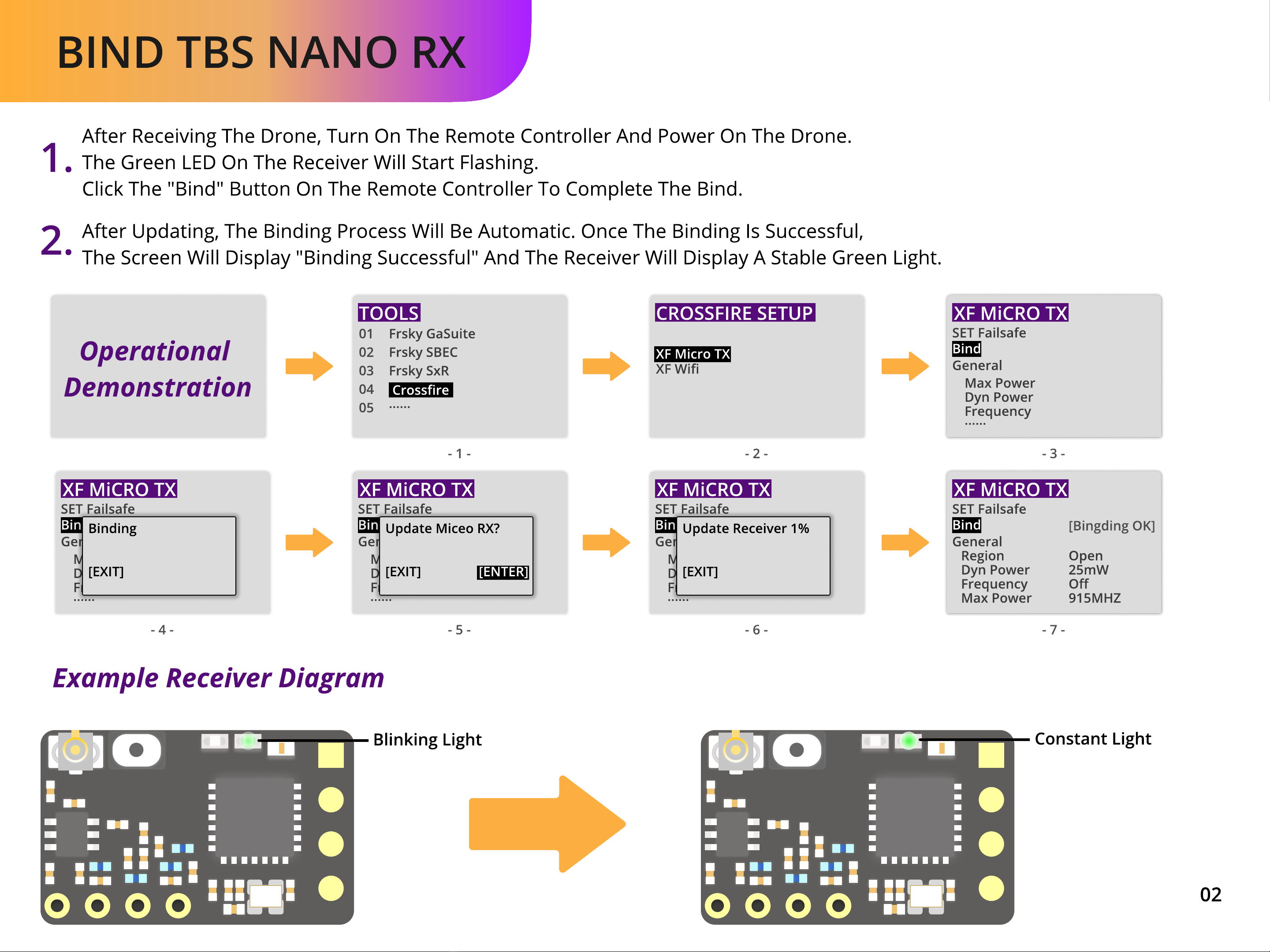
Bind TBS Nano RX ..........................................................................................................
.........................................................................................................
........................................................................................................................
02
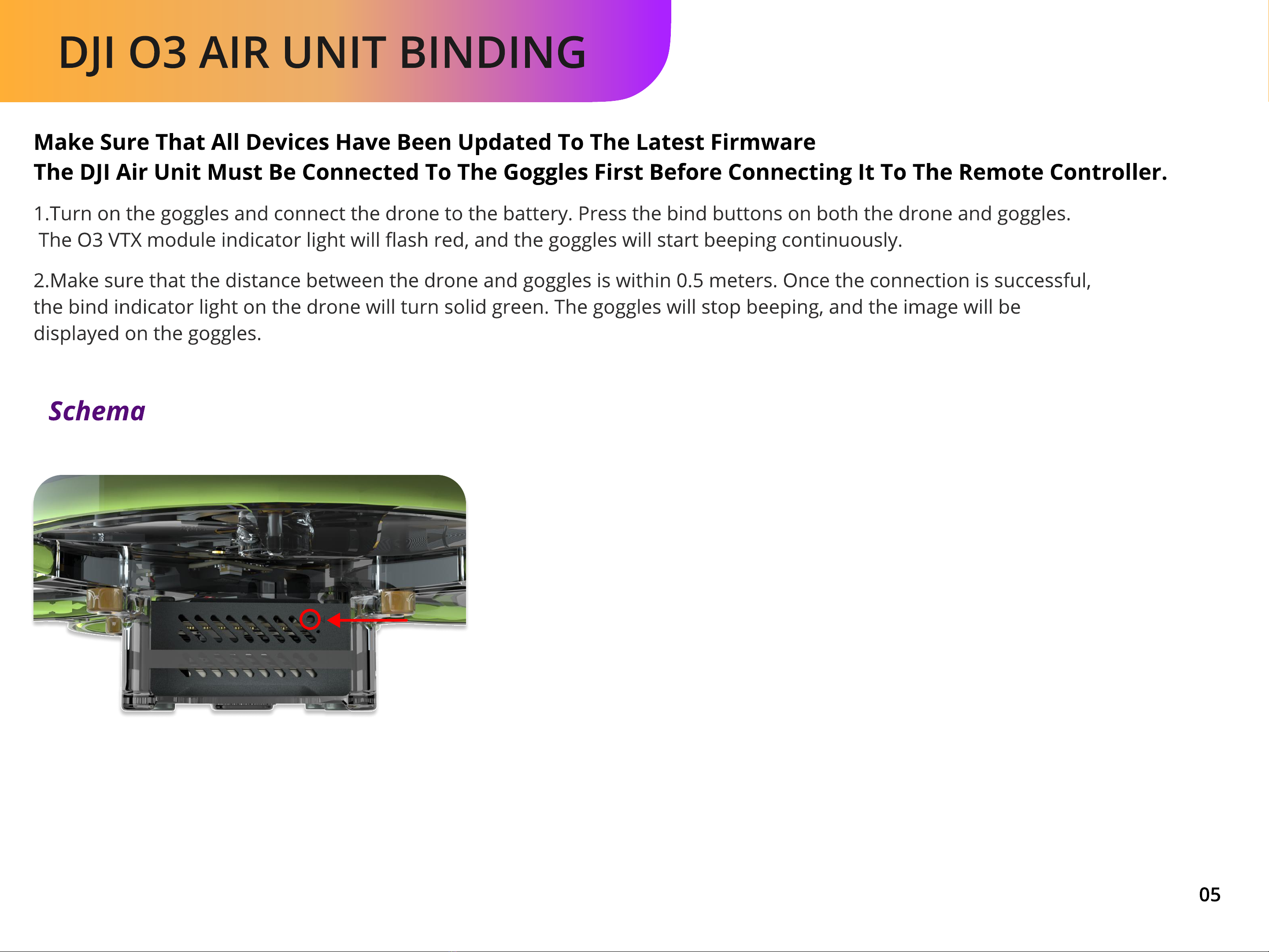
DJI O3 Air Unit Bindin 05
Bind XM+ ........................................................................................................................
..................................................................................................................
03
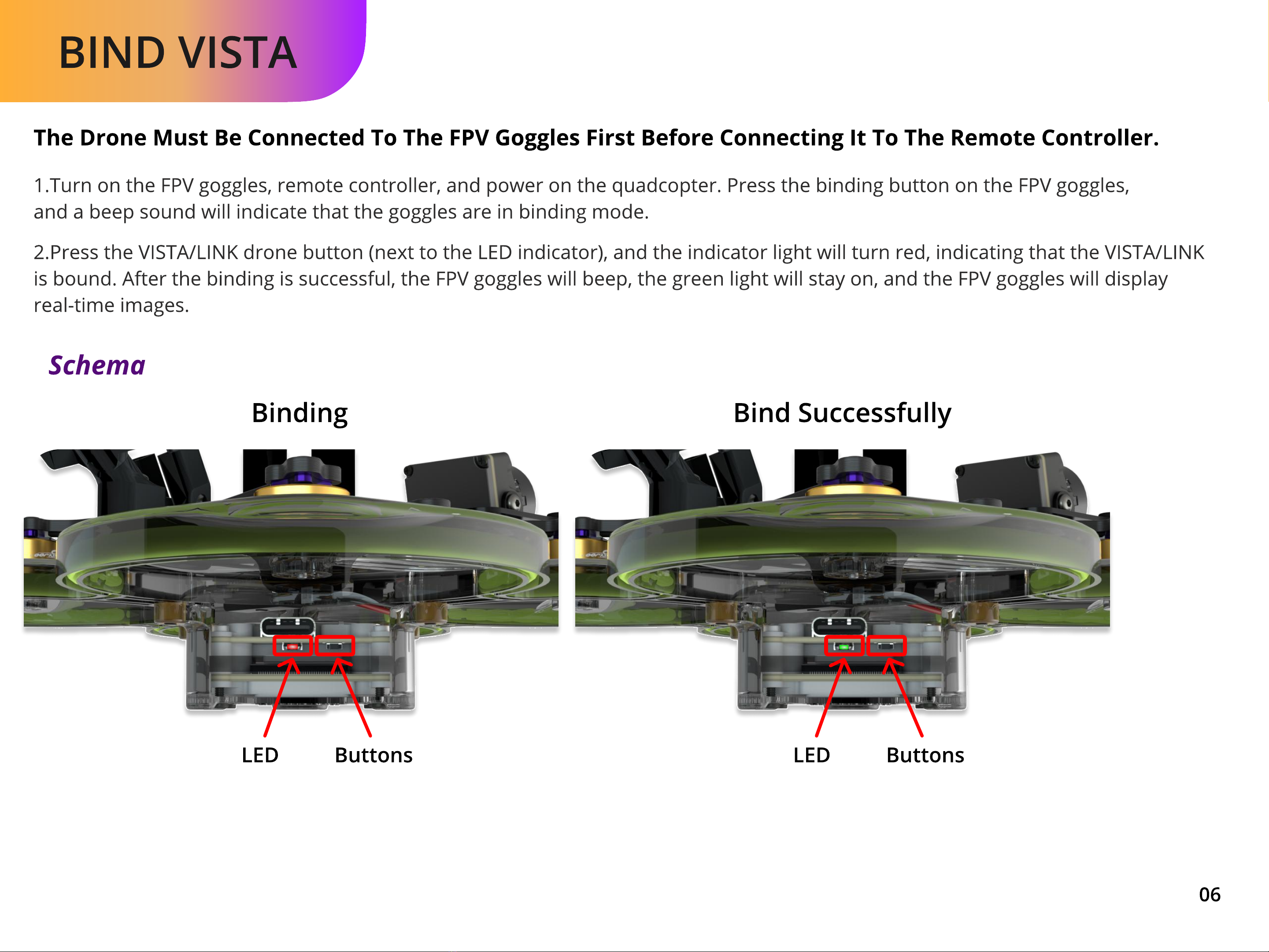
Bind VISTA 06
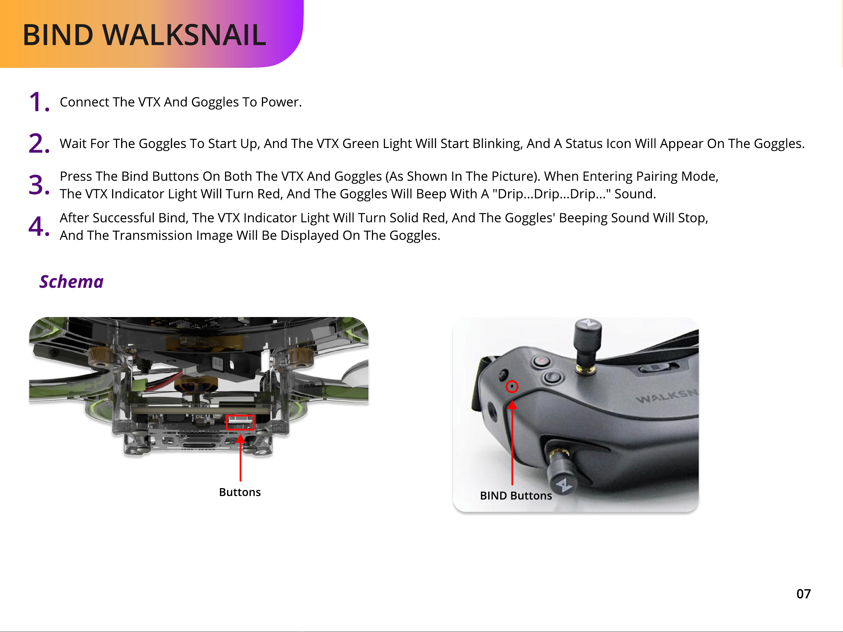
Bind Walksnail 07
Bind HDzero 08
Adjustment of VTX Power and Channels(ANLOG) 09
Modes & LED 10
Propeller Direction 11
prei ht check 12
PART2-Goggle Binding
PART3-VTX Adjustment
PART4-Mode Channel Setup
PART
5
-Propeller
I
nstallation
/
Ta
k
eo
Precautions
E
x
pansion Module
-
GPS Installation 13
GPS
s
ettin s
/
Compass
s
ettin s 15
Compass cali
b
ration 16
LED
s
trip
r
eplacement 19


 user manual")