Teal GOLDEN EAGLE User manual

01
1
2
3
4
5
6
7
1
2
3
1
2
GOLDEN EAGLE SYSTEM
FIELD MAINTENANCE
& SCHEDULE
Field-replaceable items are parts that can easily be replaced in the field without requiring special expertise or
tools other than those provided in the Field Spares Kit. Repairs, upgrades, or software updates that cannot be
performed in the field are beyond the scope of this manual, and doing so may void conditions and terms of the
warranty.
FIELD REPLACEABLE ITEMS
MAINTENANCE SCHEDULE
AFTER 10 FLIGHT
HOURS (OR AS
NEEDED)
Clear and format SD Card media
Clean all sensors and the vehicle with a damp cloth and a can of air
Fully discharge all batteries and charge back to full capacity
Verify that the gimbal and camera connectors and securely seated
Update the Golden Eagle and the TAC software
Delete and re-download oine maps to ensure the latest versions
Clear flight logs from the Golden Eagle
AFTER 150 FLIGHTS
(OR AS NEEDED)
Replace propeller assemblies
Replace rotor arm assemblies
Retire battery pack after 150 charge/discharge cycles
ROTOR ARM REPLACEMENT
Damaged or worn rotor arms require the entire assembly to be replaced but can easily be done so in the field.
The arms are prewired with the motor installed, and only need to be locked into place and secured with a
single Torx T8 screw per arm. The Torx T8 screwdriver is included in the Field Repair Kit.
Arms are keyed to the appropriate sockets on the airframe so that CW and CCW arms cannot be inadvert-
ently interchanged.
REPLACEMENT
INSTRUCTIONS
Place the drone on its back on a table or workspace where the antenna
can hang o the edge to prevent being damaged.
Remove the single T8 Torx screw on the motor arm using a T8 Torx
screwdriver.
© 2022 Teal Drones, Inc. SUP-00005, REV A

!
Step 4
3
4
5
6
7
1
2
3
4
5
REPLACEMENT
INSTRUCTIONS
(CONTINUED)
Set the screw aside for re-use.
Carefully pull the arm straight out from its socket in the drone.
Insert the new arm into the airframe. Push firmly until you feel the connectors
“click”.
NOTE: If you feel any resistance and the arm will not easily click into place,
ensure that you are not attempting to insert a CW arm into a CCW position,
and vice-versa.
Tools Needed:
One (1) T8 Torx Screwdriver
Removal:
One (1) T8 Torx Screw Per
Rotor Arm
Use a Torx T8 screwdriver to tighten the screw to 0.6N*m (0.44 ft-lbs) and
secure the arm into place.
Make sure that the motor functions properly before the next flight.
CAMERA & GIMBAL PAYLOAD REPLACEMENT
Both the FLIR Hadron EOIR camera and gimbal can be replaced in the field. Use the specific tools to ensure
that no components are damaged in the process. Use the following instructions to replace both parts.
REPLACEMENT
INSTRUCTIONS
Place the drone on its back on a table or workspace where the antenna can
hang o the edge to prevent being damaged.
Remove the two (2) M3 x 8mm screws on the gimbal brackets using a T8
Torx screwdriver.
Tools Needed:
One (1) T8 Torx Screwdriver
Removal:
Two (2) M3 x 8mm Screws
Set the screws aside for re-use.
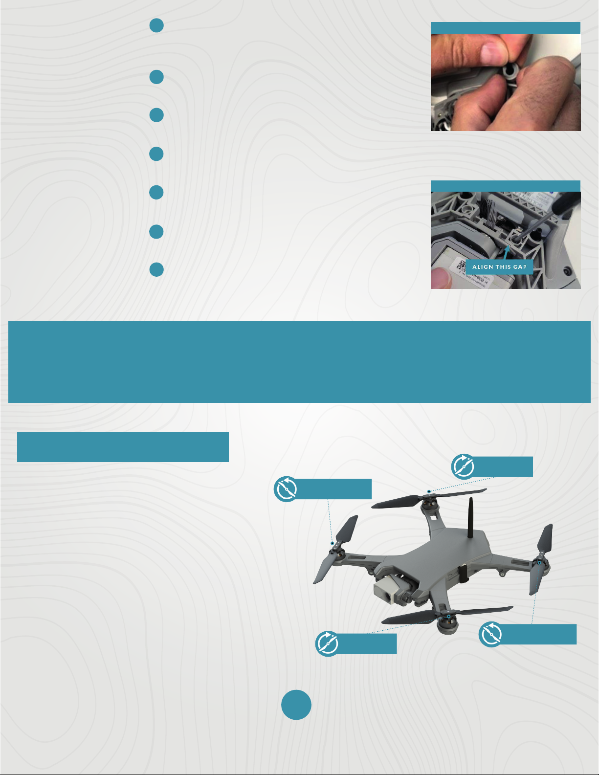
Squeeze the side latches of the camera data
cable connector to release the connector (as
shown in the image to the right).
Carefully pull the connector straight up to
disconnect it from its socket in the drone.
02
© 2022 Teal Drones, Inc. SUP-00005, REV A

Step 15
Step 10
Step 6
Step 18
Step 14
6
7
8
9
10
11
12
13
14
15
16
17
18
19
CAUTION: The exposed PCB is ESD
sensitive and static discharge can damage
the electronics. Minimize handling of the
exposed PCB.
Use your fingernail or a flathead screwdriver to
press on the tab on the motor control cable
connector (as shown in the image to the right).
Carefully pull the connector up to disconnect it
from its socket in the drone.
REPLACEMENT
INSTRUCTIONS
(CONTINUED)
Use a T5 Torx screwdriver to remove the
four (4) M1.6 x 4mm screws from the back of the Hadron camera.
Set the screws aside for re-use.
Disconnect the Hadron camera from the gimbal
by carefully pulling it away from the gimbal (as
shown in the image to the right).
Tools Needed:
One (1) T5 Torx Screwdriver
Removal:
Four (4) M1.6 x 4mm Screws
Check that the gasket around the PCB on the
Hadron camera is properly aligned and adjust if
needed.
Push the Hadron camera onto the gimbal. Press
firmly until you feel the connector “click” into
place.
Use a T5 Torx screwdriver to secure the four (4)
M1.6 x 4mm screws in the back of the Hadron
camera.
Connect the camera data cable connector to
the mating socket in the drone so that the side
of the cable as shown in the image to the right
is facing towards the front of the drone.
Connect the gimbal motor cable connector to
the mating socket in the drone so that the tab
on the connector is facing toward the front of
the drone (as shown in the image to the right).
Align the threaded inserts on the gimbal under
the holes on the gimbal brackets.
Place the two (2) M3 x 8mm screws into the
holes on the gimbal brackets.
Align the gaps (as shown in the image to the
right).
Use a Torx T8 screwdriver to tighten the
screws to 0.6 N*m (0.44 ft-lbs).
03
© 2022 Teal Drones, Inc. SUP-00005, REV A

2
1
3
4
5
6
✓
✓
✓
7
8
9
Step 5
Step 7
Step 9
PAYLOAD MOUNTING BRACKET REPLACEMENT
The gimbal brackets can be easily replaced in the field; however, the black silicone gimbal dampers
cannot. If the dampers need to be replaced or serviced, please contact Teal Drone Customer Support or
an authorized service center.
REPLACEMENT
INSTRUCTIONS
Place the drone on its back on a table or workspace where the antenna can
hang o the edge to prevent being damaged.
Make sure that the camera data cable and gimbal motor cable are not
strained in any way.
Remove the two (2) M3 x 8mm screws on the gimbal brackets using a T8
Torx screwdriver.
Tools Needed:
One (1) T8 Torx Screwdriver
Removal:
Two (2) M3 x 8mm Screws
Set the screws aside for re-use.
Use your fingers or plastic pliers that will not
damage the silicone damper to hold the body of
one of the front dampers in place (as shown in
the image to the right).
Firmly, but slowly, pull the bracket away from the
damper body until the end of the damper pulls
through the hole.
Follow the same directions to remove the rear
damper (as shown in the image to the right).
Remove the remaining dampers.
Set the new bracket so that the recesses for the
screw head and dampers are visible and away
from the body of the drone (as shown in the
image to the right).
Manually move the gimbal pitch and roll axis and check for binding or obstructions.
Ensure that no wires are pinched.
Power on the system and confirm the gimbal properly functions and is properly oriented.
SYSTEM
CHECKOUT
04
© 2022 Teal Drones, Inc. SUP-00005, REV A
10
11
12
13
14
15
16
Step 10
Step 15
✓
✓
✓
!
REPLACEMENT
INSTRUCTIONS
(CONTINUED)
Hold the bracket in place and pull the end of
the silicone damper through the hole in the
bracket (as shown in the image to the right).
Make sure that the damper is properly seated
in the bracket.
Repeat this procedure for the remaining
dampers.
Align the threaded inserts on the gimbal
under the holes on the gimbal brackets.
Place the two (2) M3 x 8mm screws into the
holes on the gimbal brackets.
Align the gaps (as shown in the image to the
right).
Use a Torx T8 screwdriver to tighten the
screws to 0.6 N*m (0.44 ft-lbs).
Manually move the gimbal pitch and roll axis and check for binding or obstructions.
Ensure that no wires are pinched.
Power on the system and confirm the gimbal properly functions and is properly oriented.
SYSTEM
CHECKOUT
PROPELLER REPLACEMENT
Individual damaged or worn propellers require
the entire 2-prop assembly to be replaced, but
are easily installed, removed, or replaced with
a simple push-and-twist method that requires
no tools or hardware.
The propeller assemblies are keyed so that
CCW and CW props cannot be inadvertently
mounted to the wrong hub.
The two CW prop assemblies have black rivets
that secure their blades, and the two CW
propeller motors have a black ring below the
spring.
The two CCW prop assemblies have silver
rivets that secure their blades, and the two
CCW propeller motors have a silver ring below
the spring.
NOTE: CW prop assemblies lock into place by turning
it in a CCW direction, and CCW prop assemblies lock
into place by turning it in a CW direction.
CLOCKWISE
PROPELLER (CW)
COUNTERCLOCKWISE
PROPELLER (CCW)
COUNTERCLOCKWISE
PROPELLER (CCW)
CLOCKWISE
PROPELLER (CW)
05
© 2022 Teal Drones, Inc. SUP-00005, REV A
Step 1
1
1
2
3
PROPELLER INSTALLATION
PROPELLER REMOVAL
To remove a prop assembly, push down and rotate it a quarter turn until it hits
its mechanical limit. Allow the spring to push the hub up, then pull the assembly
o the shaft.
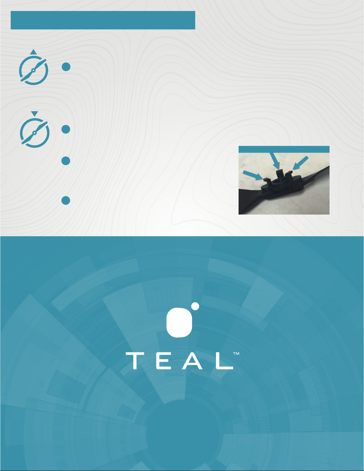
To attach a prop assembly to a motor, line up and insert the three (3) bent legs on
the underside of the prop assembly into the three (3) slots on the motor (as
shown in the image to the right).
Push down to compress the spring on the
shaft, then rotate a quarter turn until it hits
its mechanical limit. Allow the spring to
push the hub up into its locked position.
Verify that the newly installed propellers
spin feely.
PROPELLER REMOVAL & INSTALLATION
TEALDRONES.COM
06
© 2022 Teal Drones, Inc. SUP-00005, REV A
Table of contents
Other Teal Drone manuals

Popular Drone manuals by other brands

HEQ
HEQ SWAN-K1 quick start guide

MicaSense
MicaSense RedEdge-M / DJI Matrice 100 Integration guide

Wowitoys
Wowitoys Folding Elf H4805 user manual

Ultimate Drone Fishing
Ultimate Drone Fishing Poseidon Pro Pre-Flight Checklist

Reely
Reely TQ Performance Drone RtF operating instructions

Autel Robotics
Autel Robotics EVO Lite Series quick start guide


