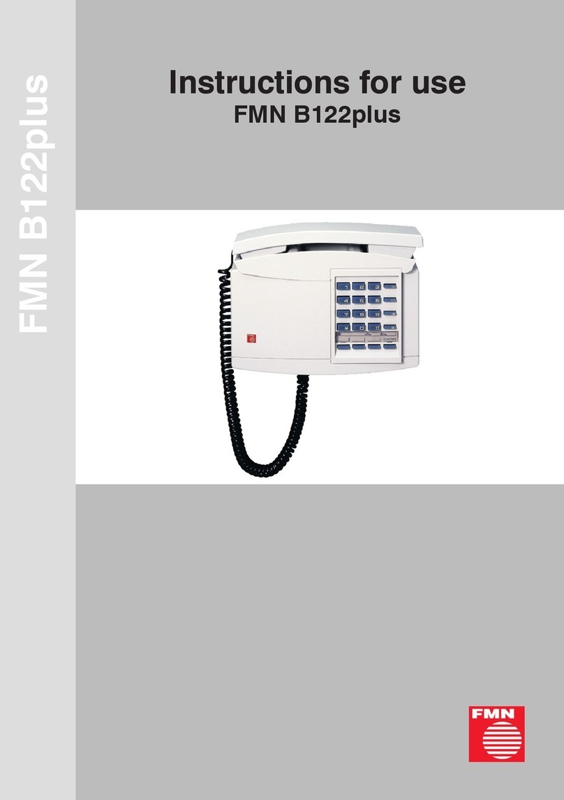
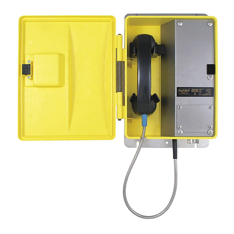
FMN alpha open air User manual

1
Instructions for use
alpha® open air

2
3
Safety precautions
l Your telephone is a wall-mounted telephone and designed for operation on an
analogue telephone line (analogue access with standard requirements) via the plug
of the telephone connecting cord. It can be connected to main lines and extensions.
l Always remove the plug of the telephone connecting cord from the wall socket
before opening the alpha open air! (Exception: when programming the unit.
Only the SET key located on the main board of the phone may be actuated
(see drawing 4).)
l Allow repairs by authorized specialists only!
l Do not use or install your phone in rooms with danger of explosion and near
electromagnetic fields (e. g. domestic appliances, TV sets or video recorders)!
l The last step when beginning operation is to plug the telephone connecting cord
into the wall socket!
l The first step when ending operation is to remove the plug of the telephone
connecting cord from the wall socket!
l The telephone connecting cord is only to be plugged into the designated socket!
l The telephone connecting cord is immediately to be removed from the socket if
there is danger of touching conductive parts due to improper use!
l Using the phone during thunderstorms is on one's own risk!
l Your telephone should only be passed on to third parties if the operating
instructions are included!
l When the telephone has reached the end of its service life, it should be disposed of
in an environmentally friendly manner!
l Danger in case of noncompliance with safety precautions
Your telephone is state of the art. However, it may be dangerous if the telephone is
not mounted and installed by qualified personnel.
l Prohibition to make any changes or modifications
The mechanical design as well as all safety-related matters of the telephone may
not be changed or modified without prior and express consent of the manufacturer.
In no event shall FMN be liable for any damages caused by such unauthorized
modification of the unit. Especially all kinds of repair and soldering works on the
main board (PCB) are prohibited.
ESD protection measures
Comply with the ESC protection measures according to
DIN EN 61340-5-1/-2 when opening the unit (potential equaliza-
tion between body and ground of the unit as well as ground of
the casing via high-value resistance (approx. 1 MOhm) e. g. usual
wrist band).

2
3
Table of contents
Safety precautions .......................................................................... 2
Table of contents ............................................................................. 3
Versions of the alpha open air / Mounting..................................... 4
1. Versions of the alpha open air .....................................................................4
2. Delivery scope .............................................................................................4
3. Mounting instructions ..................................................................................4
3.1 Mounting on a wall with cable entry at the bottom of the casing .............4
3.2 Mounting on a wall with the cable leading through the back panel of
the casing ..................................................................................................5
Installation ....................................................................................... 6
4. Installation ....................................................................................................6
Telephone with 4 destination dialling keys.................................... 7
5. Settings ........................................................................................................7
5.1 Notes..........................................................................................................7
5.2 Telephone with 4 destination dialling keys ................................................7
5.2.1 Default setting .........................................................................................7
5.2.2 Normal telephone function (Default setting) ..........................................8
5.2.3 Programming the flash key.....................................................................8
5.2.4 Programming manual direct station selection........................................8
5.2.5 Programming automatic direct station selection....................................9
5.2.6 Programming the destination dialling keys ............................................9
Telephone with automatic direct station selection ........................ 9
5.3 Telephone with automatic direct station selection ..................................10
5.3.1 Default setting .......................................................................................10
5.3.2 Programming the destination dialling key............................................10
Connection permit/Warranty/Consumer Advice/Conformity ...... 10
6. Connection permit .....................................................................................10
7. Warranty.....................................................................................................11
8. Consumer Advice ......................................................................................11
9. Conformity..................................................................................................11

4
5
1. Versions of the alpha open air
Following versions are covered by these instructions for use:
alpha open air with 4 destination dialling keys
telephone with 4 programmable destination dialling keys; can be used in
several operating modes (see point 5.2)
alpha open air without keypad (automatic direct station selection)
with automatic direct station selection, when lifting the handset the number
preprogrammed in the telephone is automatically dialled out (see point 5.3)
Mounting and installation of both versions is according to points 3 and 4. Features of
each version and their programming are described in point 5.
2. Delivery scope
• 1 alpha open air • 4 hexagon head wood screws 6x50
• 1 folding ferrite • 4 sealing washers (plastic)
• 1 instructions for use • 4 washers (steel)
• 1 offset screw driver
3. Mounting instructions
You can mount the alpha open air on a wall or a pole.
It can be mounted on a pole using two mounting clips (not within the delivery scope)
which are screwed on the 4 fixing holes of the back panel of the casing.
The cable entry for the telephone connecting cord is foreseen at the bottom of the
back compartment (as supplied). It can also be lead through the back panel of the
back compartment if the telephone connecting cord is not to be accessible from
outside. Please follow the instructions below:
3.1 Mounting on a wall with cable entry at the bottom of the casing
1. Mark the 4 fixing points on the wall according to drawing 1 or the drilling template
(see last page of instructions).
2. For mounting on a solid wall: drill holes into the marked fixing points and put dow-
els into the drilled holes (e. g. 8 mm dowels); for mounting on a wood wall etc.:
drill holes (∅4 mm) into the marked fixing points.
3. Take the alpha open air out of the packaging. Remove the front panel from the
back compartment by loosening the 4 Security-TORX screws (tool: offset screw
driver). Unplug the connector of the handset and the telephone connecting cord
from the main board (PCB), lay the front panel aside.
4. Fix the back compartment of the casing into the wall using the 4 hexagon head
wood screws supplied each together with one steel and one plastic washer
(for sealing purposes); further with point 4: Installation.
Versions of the alpha open air / Mounting

4
5
3.2 Mounting on a wall with the cable leading through the back panel of
the casing
1. Mark 4 fixing points and the drilling for the cable leading (back panel) on the wall
according to drawing 1 or the drilling template (see last page of instructions).
2. For mounting on a solid wall: drill holes into the marked fixing points and put
dowels into the drilled holes (e. g. 8 mm dowels);
for mounting on a wood wall etc.: drill holes ∅4 mm into the marked fixing points.
3. Cable entry on the back panel: drill a hole (min. ∅ 6 mm) into the marked point.
4. Take the alpha open air out of the packaging. Remove the front panel from the
back compartment by loosening the 4 Security-TORX screws (tool: offset screw
driver). Unplug the connector of the handset and the telephone connecting cord
from the main board (PCB), lay the front panel aside.
5. Remove the connecting cord by unscrewing the 2 pin screw terminal, pull the cord
out of the ferrite ring, the protection sleeve remains in the casing. Pull the connect-
ing cord through the drill hole in the fixing panel and through the protection sleeve
in the back panel. Pull the cord twice through the ferrite ring and screw it back onto
the 2 pin screw terminal.
6. Fix the back compartment of the casing to the wall using the 4 hexagon head wood
screws supplied each together with one steel and one plastic washer (for sealing
purposes).
Drawing 1
ø
8
approx. 1200
120
124
le
Drilling orcabentry
f
min.diameter 6mm
30
44
Ferrite ring
Mounting
Dimensions with
protection-frame:
height: 332 mm
(without handset cord)
width: 326 mm
depth: 130mm (with handset)
Dimensions without
protection-frame:
height: 260 mm
(without handset cord)
width: 250 mm
depth: 130mm (with handset)

6
7
4. Installation
1. Plug the connectors of the telephone connecting cord and the handset cord back
onto the main board; place the folding ferrite supplied at least 10 cm behind the
end of the armoured metal handset cord (according to drawings 2 / 3) and snap it
into place. (Note: Take care of the distance of at least 10 cm when assembling the
phone. The handset cord needs to be laid in a loop into the casing.)
2. If you do not want to change the settings (see point 5 Settings) fix the front panel
back onto the casing using the 4 Security-TORX screws. (tool: offset screw driver)
3. Plug the plug of the connecting cord back into the telephone socket.
Drawing 2
1 2
armoured metal
handset cord
folding ferrite
approx.100
handset cord
Telephone with 4
destination dialling keys
telephone connecting
cord
to hook switch
armoured metal
handset cord
folding ferrite
telephone connecting
cord
approx.100
handset cord
Drawing 3
1 2 3 F
4 5 6 E
7 8 9 D
A 0 B C
Telephone with automatic
direct station selection
Each version of the alpha open air has a different default setting. The default settings
are described in points 5.2.1 and 5.3.1. If you want to make any changes, follow the
instructions on the following pages.
Installation

6
7
Telephone with 4 destination dialling keys
5. Settings
The alpha open air needs to be opened in order to be able to make settings and
program the destination dialling keys (remove the front panel from the casing by
unscrewing the 4 Security-TORX screws).
5.1 Notes
lThe destination dialling memories are automatically cleared if the operation
mode is changed. They need to be programmed anew if required.
lAccording to point 5.2.5, the telephone will be in working condition if the
destination dialling key 1 (or A see drawing 3) is programmed with a
call number.
l Changes of settings become effective by replacing the handset.
lThe telephone can only be programmed when it is connected to the
telephone line.
lThe Set key can be pressed by using a small screw driver or a similar tool.
lAll settings remain when the telephone is disconnected from the
telephone line.
lImportant: This telephone does not have a ringer, also pulse dialling, ground
and last number redial are not possible.
5.2 Telephone with 4 destination dialling keys
Description of the operating panel: telephone with 4 destination dialling keys
Destination
dialling key 4
(Flash key)
Destination
dialling key 1
Back view of main board with cover
Drawing 4
1 2
to hook switch
telephone connecting
cord
1 2 3 4
Set key
Destination
dialling key 2
Destination
dialling key 3
1 2 3A
B
6
54
789
0
C
D
ABC DEF
MNOJKLGHI
PQRS TUV WXYZ
5.2.1 Default setting
lAnalogue standard telephone with DTMF dialling without reservation
l4 destination dialling memories with a maximum of 20 digits each (empty)
5.2.2 Normal telephone function (default setting)
Dialling and communication is possible without reservation.
If your telephone is set in accordance with points 5.2.3 - 5.2.5, you can reset it to
normal telephone function (default setting) as follows:

8
9
- handset is off-hook
- press Set key (see drawing 3)
- press Digit key 1
- press Set key
5.2.3 Programming the flash key
The second destination dialling key has a double function. It is the flash key in this
mode. The flash time can be set. Dialling and communication is possible without
reservation.
Setting:
- handset is off-hook
- press Set key
- press digit key 2
- press Set key
Setting the flash time:
- handset is off-hook
- press Set key
- press Digit key 0 and the relevant code (0 to 7, see below)
- press Set key
Codes and their meaning:
- Code 0: Flash time: 80 ms
- Code 1: Flash time: 90 ms (default setting)
- Code 2: Flash time: 120 ms
- Code 3: Flash time: 180 ms
- Code 4: Flash time: 240 ms
- Code 5: Flash time: 300 ms
- Code 6: Flash time: 360 ms
- Code 7: Flash time: 480 ms
5.2.4 Programming manual direct station selection
Four destination dialling keys are available (for programming destination dialling keys
1 to 4 see Point 5.2.6). Generally, dialling must be started via one of the destination
dialling keys. The handset microphone is deactivated until then. Once the destination
dialling key is pressed, the microphone is activated and the keypad unlocked. It then
can be used without reservation.
Setting:
- handset is off-hook
- press Set key
- press Digit key 3
- press Set key
5.2.5 Programming automatic direct station selection
Automatic direct station selection is activated by lifting the handset. The number pre-
programmed on the destination dialling key 1 is dialled out automatically (see point
5.2.6). Once the number of destination dialling key 1 is dialled out, the microphone is
activated and the keypad is unlocked. It can be used without reservation.
Setting:
Telephone with 4 destination dialling keys

8
9
Telephone with 4 destination dialling keys / automatic direct station selection
- handset is off-hook
- press Set key
- press Digit key 4
- press Set key
Note: The telephone is in working condition if the destination dialling key 1 is
programmed with a call number.
5.2.6 Programming the destination dialling keys
Setting:
- handset is off-hook
- press Set key
- press Destination dialling key 1, 2, 3 or 4
- enter number (previously programmed numbers will be overwritten)
- press Set key
5.3 Telephone with automatic direct station selection
In addition to point 5.1 please note the following:
lThe telephone will be in working condition if key F is programmed with a
call number.
lImportant: This telephone does not have a ringer, also pulse dialling, ground,
flash and last number redial are not possible.
One destination dialling key is available. Automatic direct station selection is activat-
ed when the handset is lifted. The number preprogrammed in the destination dialling
memory is dialled out automatically (for programming the destination dialling me
mory, see point 5.3.2). Once the number is dialled out, the microphone is activated.
front panel
main board with
keypad located on the
back of the front panel
Security-
TORX screw
Drawing 5

10
11
Telephone with automatic direct station selection / Connection permit
Drawing 6
1 2 3 F
4 5 6 E
7 8 9 D
A 0 B C
keypad key F
key E
Back view of main board
Description of the operating panel
5.3.1 Default setting
ltelephone with automatic direct station selection - DTMF dialling
l1 destination dialling memory with a maximum of 20 digits,
(the memory is empty or preprogrammed by default with a call number
(option))
5.3.2 Programming the destination dialling key
- remove the front panel (see drawing 5)
- lift the handset
- press key E of the keypad located on the back of the front panel (see drawing 6)
- press key F of the keypad (= destination dialling key)
- enter number (previously programmed call numbers will be overwritten)
- press key E of the keypad
- replace the handset after fixing the front panel to the back compartment.
6. Connection permit
This telephone is designed for connection to analogue telephone lines (analogue
access with standard requirements) of the public telecommunications network. It may
be connected and operated by any person.
The telephone is compliant with the harmonized standards for connection to public
telecommunications networks.
This, however, is no guarantee for successful operation of the telephone unit on each
network termination point due to the differences in the public telecommunications
network between the different countries.
For operating problems, contact your specialist dealer.

10
11
Warranty / Consumer Advice / Conformity
7. Warranty
• The liability for defects and other damages complies with the regulations of our
general conditions of supply and terms of trade.
• Claims based on defects are subject to a limitation period of 12 months, as far as
the law - particularly Sec. 479 para. 1 German Civil Code (“BGB”) (rights of re-
course) - does not prescribe longer terms.
All parts or services where a defect as to quality becomes apparent within the limita-
tion period shall, at our discretion, be repaired, replaced or provided again free of
charge provided that the reason for the defect had already existed at the time when
the risk passed. In case that the customer is consumer in terms of
Sec. 3 German Civil Code, the legal requirements apply.
• Other claims for reimbursement of expenses, based on whatever legal reason, in-
cluding infringement of duties arising in connection with the contract or tort, shall be
excluded, as far as mandatory liability shall not apply, e. g. according to the German
Product Liability Act (“Produkthaftungsgesetz”), in the case of intent, gross negli-
gence, injury of life, body or health, or breach of a condition which goes to the root
of the contract (“wesentliche Vertragpflichten”).
• Damages caused by improper use, operation, storage, maintenance as well as by
influences beyond one‘s control or other outside influences, do not come under the
warranty, furthermore not the consumption of consumer goods.
• Claims based on defects attributable to improper modifications or repair work car-
ried out by the purchaser or third parties and the consequences shall likewise be
excluded.
8. Consumer advice
In case that our customer is consumer in terms of Sec. 13 German Civil Code, an
absolute right of return of 2 weeks after receipt of the goods - without giving any
reasons - is granted according to Sec. 356 German Civil code.
For the observance of the prescribed period, it is sufficient to send back the goods
within the prescribed period or to send the written request for return to
FMN communications GmbH, Grimmelallee 4, 99734 Nordhausen. In case the
goods have a value of up to 40 Euro, the regular costs of sending back the goods will
have to be paid by the consumer.
9. Conformity
The FMN communications GmbH declares that the telephone “alpha open air”
complies with the essential requirements and the other relevant provisions of the
directive 1999/5/EG (R&TTE Directive).
The complete declaration of conformity can be found and downloaded
on our website http://www.fmncom.com.
Copyright
All rights reserved. Duplication of these instructions for use or parts thereof by any reproduction method whatsoever is not
permitted without prior permission of the manufacturer.
Amendments may be published without prior notification.
Notwithstanding the above declaration, the manufacturer accepts no liability for
errors in these instructions or their consequences.

FMN communications GmbH
Grimmelallee 4 99734 Nordhausen
P. O. Box 10 04 65 99724 Nordhausen
Phone +49 (36 31) 56-50 00
Fax +49 (36 31) 56-32 24
Internet www.fmncom.com
HOTLINE +49 (36 31) 56-34 16
We are at your disposal to answer your questions.
Subject to change.
Instructions for use 2006.3.0160.02
Edition: No. 05/09 (1111-5385)
Drilling template
∅8 (Mounting using dowels e. g. solid wall)
∅4 (Mounting without dowels e. g. wood wall)
min.∅6
Table of contents
Other FMN Telephone manuals
