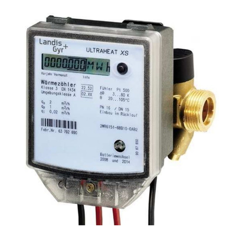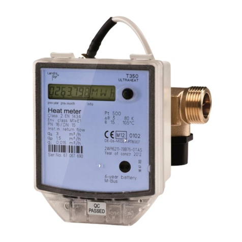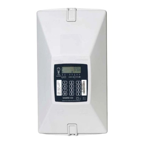
Table of contents 3/96
D000062026 en a –E650 Series 4 –ZMD400AT/CT, ZFD400AT/CT –User Manual © Landis+Gyr
Table of contents
Revision history ...................................................................................................................................2
Table of contents .................................................................................................................................3
About this document............................................................................................................................5
1Safety...........................................................................................................................................6
1.1 Safety information...................................................................................................................6
1.2 Responsibilities.......................................................................................................................6
1.3 Safety regulations ...................................................................................................................7
1.4 Radio interference...................................................................................................................7
1.5 Safety-related meter data........................................................................................................8
2Device description......................................................................................................................9
2.1 Field of application..................................................................................................................9
2.2 Standards..............................................................................................................................10
2.3 Characteristics ......................................................................................................................11
2.4 Type designation...................................................................................................................13
2.5 Block schematic diagram ......................................................................................................14
2.6 Measuring system.................................................................................................................17
2.6.1 Input signals ....................................................................................................................17
2.6.2 Signal processor..............................................................................................................18
2.6.3 Measured quantities ........................................................................................................20
2.6.4 Formation of measured quantities....................................................................................21
2.6.5 Summation channels.......................................................................................................27
2.7 Data profile............................................................................................................................27
2.7.1 Stored value profile..........................................................................................................27
2.7.2 Load profile 1 and load profile 2 (option)..........................................................................27
2.7.3 Event log..........................................................................................................................28
2.8 Communication.....................................................................................................................31
2.8.1 Optical interface...............................................................................................................31
2.8.2 Communication units .......................................................................................................31
2.9 MAP software tools...............................................................................................................33
2.10 Anti-tampering features.........................................................................................................34
2.10.1 DC magnet detection.......................................................................................................34
3Mechanical construction..........................................................................................................35
3.1 Housing.................................................................................................................................35
3.2 Faceplates ............................................................................................................................39
3.3 Connections..........................................................................................................................40
3.4 Connection diagrams (examples)..........................................................................................42
3.5 Dimensions...........................................................................................................................46
4Installation and uninstallation .................................................................................................47
4.1 Basic information for connecting the meter............................................................................47
4.1.1 Connection to low voltage with current transformers........................................................47
4.1.2 Connection to medium and high voltage (Aron circuit).....................................................48
4.1.3 Connection to medium and high voltage (three-phase four-wire circuit)...........................49
4.2 Mounting the meter...............................................................................................................50
4.3 Connecting the meter............................................................................................................52
4.3.1 Connecting the phase connection lines............................................................................53
4.3.2 Connecting the signal inputs and outputs ........................................................................54
4.3.3 Maximum current of auxiliary current outputs...................................................................55
4.3.4 Connection of active inputs..............................................................................................56
4.3.5 Connecting the RS485 interface......................................................................................56

