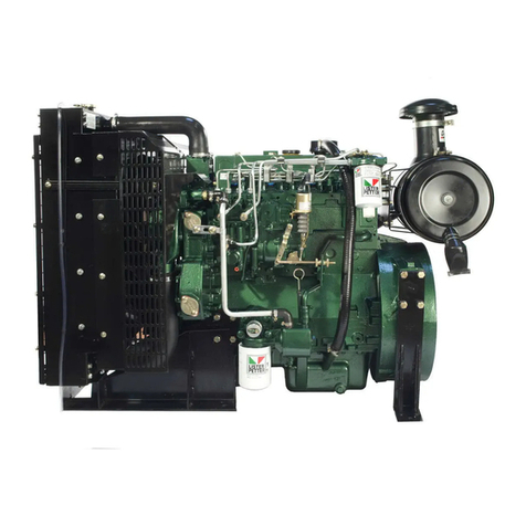
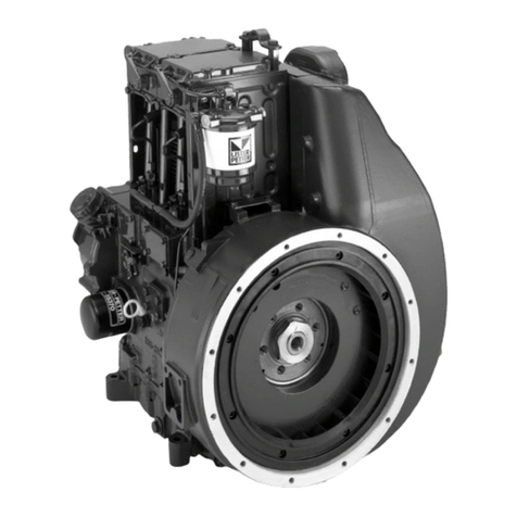
Lister Petter TS1 Instruction manual

P027-08270 | edition 8 | April 2021
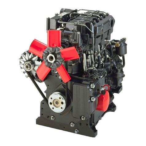
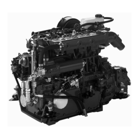
TS, TR, TX Engines
Workshop Manual
T SERIES

TS, TR, TX engines workshop manual 2
Disclaimer
The information, specications, illustrations, instructions and
statements contained within this publication are given with
Lister Petter Power Systems' best intentions and are believed
to be correct at the time of going to press.
Our policy is one of continued development and we reserve
the right to amend any technical information with or without
prior notice.Whilst every eort is made to ensure the accuracy
of the particulars contained within this publication neither
the Manufacturer, the Distributor nor the Dealer shall in
any circumstances be held liable for any inaccuracy or the
consequences thereof.
The information given is subject to the Company’s current
Conditions ofTender and Sale, is for the assistance of users and
is based upon results obtained from tests carried out at the
place of manufacture. The Company does not guarantee that
the same results will be obtained elsewhere under dierent
conditions.
© Copyright Lister Petter Limited Power Systems
All rights reserved
Associated Publications
Operators Handbook P027-08185
TS, TR Master Parts Manual P027-08030
TX Master Parts Manual P027-08929
Technical Handbook P027-09212

TS, TR, TX engines workshop manual 3
Introduction
1. General Information
1.1 Safety Precautions and Safe Working Practices 6
1.2 Safety Symbols 8
1.3 Engine Features 9
1.4 Engine Identication 10
1.5 Battery Details 10
2. Engine Servicing & Adjustments
2.1 Preliminary Instructions 12
2.2 The Air Cleaner 12
2.3 The Cold Start Aid 12
2.4 The Manifolds 13
2.5 The Air Cowling 14
2.6 The Cylinder Cooling Fins 14
2.7 The Axial Fan - TX 14
2.8 Drive Belt Tension 15
2.9 Axial Fan Drive Guard - TX 15
2.10 The Cylinder Head Cover 15
2.11 The Cylinder Head 15
2.12 Cylinder Head Clearance 16
2.13 The Valve Rocker Stub Shafts - TS/TR 17
2.14 The Valve Rockers - TX 17
2.15 The Valves 18
2.16 The Valve Guides 18
2.17 The Valve Seats 19
2.18 Valve Clearance 20
2.19 The Decompressor 20
2.20 The Crankshaft Pulley - TX 21
2.21 The Gear End Cover 21
2.22 The Fuel Tank 22
2.23 The Fuel Filter 22
2.24 Priming the Fuel System 23
2.25 The Fuel Lift Pump 23
2.26 The Fuel Injector 24
2.27 The Fuel Pump 25
2.28 Fuel Pump Timing 27
2.29 Governor Modications 29
2.30 The Governor 29
2.31 Setting the Governor 30
2.32 Governor 'G' Setting and Timing Tables 33
2.33 Speed Adjustment 34
2.34 The Engine Controls 34
2.35 The Fuel Pump Tappet 35
2.36 The Camshaft 35
2.37 The Camshaft Gearwheel 36
2.38 The Camshaft Bushes 37
2.39 The Cylinder Barrel 38
2.40 The Piston and Connecting Rod 39
2.41 The Flywheel 40
2.42 The Fanshroud - TS/TR 40
2.43 Flywheel Housing - TX 41
2.43 Main Bearing Housing 41
2.44 The Crankshaft 42
2.45 Crankshaft End Float 44
2.46 Checking Bearing Clearance 44
2.47 Crankshaft Main Bearings 44
2.48 Gear End Drives 46
2.49 The Oil Filter 46
2.50 The Oil Dipstick 47
2.51 The Oil Sump 47
2.52 The Oil Strainer and Pump 48
2.53 The Oil Seals 48
3. Engine Fluids
3.1 Engine Fluids - Lubricating Oil 50
3.2 Engine Fluids - Fuel 51
4. Operating Instructions
4.1 Preliminary Instructions 53
4.2 Hand Starting 54
4.3 Electric Starting 55
4.4 Stopping the Engine 55
5. Routine Maintenance
5.1 Preliminary Instructions 56
5.2 Routine Maintenance - Schedule Hours 56
5.3 Spanner Torque Settings 57
5.4 Jointing Compounds 58
5.5 Dimensions of Wearing Parts 58
5.5 Long Term Storage 63
6. Troubleshooting
6.1 Preliminary Information 64
6.2 Method of Troubleshooting 64
6.3 Troubleshooting Tables 64
7. Dismantle & Rebuild
TS/TR Dismantle and Rebuild 67
TX Dismantle and Rebuild 69
Contents

TS, TR, TX engines workshop manual 4
8. Flywheel Charge Windings
8.1 Charge Windings 72
8.2 Syncro Charge Windings 72
8.3 Nicsa Charge Windings 75
9. Electrical Wiring Diagrams
9.1 Wiring Diagrams 79
10. Technical Data
10.1 Engine Mechanical Data - TS 86
10.2 Engine Mechanical Data - TR 87
10.3 Engine Mechanical Data - TX 88
10.4 Builds - TS 89
10.5 Builds - TR 90
10.6 Builds - TX 91
11. Conversion Factors
11.1 Formulae 92
11.2 Conversion Factors 93
12. Index

TS, TR, TX engines workshop manual 5
Introduction
The purpose of this manual is to give information, operating,
maintenance and repair procedures for the 'T' Series of
engines.
Themanualisdesignedprimarily forusebyqualiedtechnicians
with electrical and mechanical experience.
This work can only be carried out if the necessary hand and
service tools are available.When the user has insucient tools,
experience or ability to carry out adjustments, maintenance and
repairs then this work should not be attempted.
Where accurate measurements, or torque values, are required
they can only be made using calibrated instruments.
Under no circumstances should makeshift tools or equipment
be used, as their use may adversely affect safe working
procedures and engine operation.
The specication details given apply to a range of engines and
not to any one particular engine. In cases of diculty the user
should consult the local Lister Petter Power Systems Distributor
or Dealer for further advice and technical assistance.
The information, specications, illustrations, instructions and
statements contained within this publication are given with
our best intentions and are believed to be correct at the time of
going to press. Our policy is one of continued development
and we reserve the right to amend any technical information
with or without prior notice.
Whilst every effort is made to ensure the accuracy of the
information contained within this publication, neither the
Manufacturer, DistributororDealershallinanycircumstancesbe
held liable for any inaccuracy or the consequences thereof.
The information given is subject to the Company’s current
Conditions ofTender and Sale, is for the assistance of users and
is based upon results obtained from tests carried out at the
place of manufacture. This Company does not guarantee that
the same results will be obtained elsewhere under dierent
conditions.
Parts that have not been approved by the Lister Petter Power
Systems organisation cannot be relied upon for correct material,
dimensions or finish. This Company cannot therefore, be
responsible for any damage arising from the use of such parts
and the guarantee will be invalidated.
When purchasing parts or giving instructions for repairs users
should, in their own interests, always specify Genuine Lister
Petter Parts and quote the Description of the Part and the
Engine Serial Number.
Training
Comprehensive training in the correct operation, service and
overhaul procedures of engines is available at the Lister Petter
Power Systems International Product Training Centre. Please
contact Lister Petter Power Systems for details.
If Problems Occur
If problems occur with your engine, or any of the Lister Petter
Power Systems approved accessories tted to it, your local Lister
Petter Power Systems Distributor should be consulted.
There are Lister Petter Power Systems Distributors in most
countries of the world and details for these can be obtained
from any one of the companies listed on the back cover.
Using this Workshop Manual
Each section title is given at the top of the relevant pages and
each section has its own‘Contents’page.
A full cross reference 'Index' appears at the back of the
manual.
It is recommended the individual steps contained in the various
maintenance or repair operations are followed in the sequence
in which they appear.
At times it may be necessary to refer to other parts of the
section, or to a dierent section, for more specic or detailed
information.
Caution and Warning Symbols
When an engine is operating or being overhauled there are a
number of associated practices which may lead to personal
injury or product damage.
Your attention is drawn to the symbols shown and described
below which are applied throughout this manual.
CAUTION
This caution symbol draws attention to special
instructions or procedures which, if not correctly
followed, may result in damage to, or destruction of,
equipment.
WARNING
This warning symbol draws attention to special
instructions or procedures which, if not strictly observed,
may result in personal injury.
WARNING
A WARNING SYMBOL WITH THIS TYPE OF TEXT DRAWS
ATTENTION TO SPECIAL INSTRUCTIONS OR PROCEDURES
WHICH, IF NOT STRICTLY OBSERVED, MAY RESULT IN
SEVERE PERSONAL INJURY, OR LOSS OF LIFE.
Note:
A note is used to draw your attention to additional or important information.

TS, TR, TX engines workshop manual 6
1. General Information
1.1 Safety Precautions and Safe
Working Practices
At all times follow the recommended precautions and safe
operating and working practices.The following are of a general
nature and more specific information appears where it is
relevant.
Caution and Warning Symbols
CAUTION
This caution symbol draws attention to special
instructions or procedures which, if not correctly
followed, may result in damage to, or destruction of,
equipment.
WARNING
This warning symbol draws attention to special
instructions or procedures which, if not strictly observed,
may result in personal injury.
WARNING
A WARNING SYMBOL WITH THIS TYPE OF TEXT DRAWS
ATTENTION TO SPECIAL INSTRUCTIONS OR PROCEDURES
WHICH, IF NOT STRICTLY OBSERVED, MAY RESULT IN
SEVERE PERSONAL INJURY, OR LOSS OF LIFE.
Follow All Safety Instructions
a. Carefully read all safety messages in this manual and the
safety and informative symbols on your engine and plant.
b. Starting any diesel engine can be dangerous in the hands of
inexperienced people. Engine operators must be instructed
in the correct procedures before attempting to start any
engine.
c. Do not make any unauthorised modications as these may
aect the safe operation of the engine and put the operator
at risk.
d. Ensure all starting devices are removed, or isolated, before
commencing any work on the engine or plant.
Emergency Considerations
a. Be prepared with suitable equipment, and knowledge, in
case a re starts.
b. Know where to make calls to the emergency services from.
c. Ensure a third party knows where you are working and when
you leave the working area.
Handling Fluids Safely
a. When working with fuel or batteries do not smoke or work
near to heaters or other re hazards.
b. Store ammable liquids away from re hazards.
c. Do not expose pressurised containers to heat and do not
incinerate or puncture them.
d. Handle fuel with care and always stop the engine before
refuelling. Do not overll the fuel tank.
e. Thoroughly clean any lubricating or fuel oil from the skin as
soon as possible.
f. Rectify all fuel, coolant and oil leaks as soon as practicable
and clean any spills when they occur.
g. Remove any build-up of grease, oil or debris.
h. Batteries contain sulphuric acid - if the acid has been splashed
on the skin, eyes or clothes flush it away with copious
amounts of fresh water and seek medical aid.
Personal Safety
a. Tie long hair close to your head.
b. Do not wear a necktie, scarf, loose clothing or necklace when
working close to a running engine.
c. It is advisable to remove rings and other jewellery to prevent
possible entanglement in moving parts.
These items could also cause an electric short circuit if any
part of the electrical system is being worked on.
d. Ensure any lifting equipment to be used has the correct
capacity to lift the engine.
e. Lifting equipment must be designed to give two vertical lifts
from directly above the engine lifting eyes.
f. The engine lifting eyes tted to the engine are suitable for
lifting the engine and accessory assemblies originally tted
by Lister Petter. They must not be used to lift the complete
plant.
g. Do not work under any plant that is only held by overhead
lifting equipment.
Personal Protective Clothing & Equipment
a. Wear close tting clothing and personal protective clothing
and safety equipment appropriate to the work being done.
b.Wear suitable ear protection to protect against objectionable
or uncomfortable loud noise.
Prolonged exposure to loud noise can cause impairment, or
loss of hearing.
c. The use of music or radio headphones could cause a loss of
concentration.
Handling Chemical Products Safely
a. Direct exposure to hazardous chemicals can cause serious
injury.
b. Potentially hazardous chemicals include such items as
lubricants, fuel, coolant concentrate, battery acid, paint and
adhesives.

TS, TR, TX engines workshop manual 7
c. Manufacturers Safety Data Sheets will provide specic details
of the physical and health hazards, safety and emergency
proceduresandany necessarypersonalprotectionequipment
required while working with hazardous materials.
Rotating Machinery
a. Entanglement with any rotating equipment can cause serious
injury or death.
b. If unprotected skin comes into contact with rotating
equipment severe burns can result.
Safe Maintenance Considerations
a. Understand the service procedures before commencing
any work.
b. Ensure the work area is clean, dry, well ventilated and has
adequate lighting.
c. Isolate the engine starting system before commencing any
work on the plant.
d. All persons using equipment or processes in connection with
the maintenance of plant and machinery must have received
adequate and suitable training.
High Pressure Fluids
a. Never allow any part of the body to come into contact with
high pressure hydraulic oil, compressed air or fuel oil, for
example when testing fuel injection equipment.
b. Both digested and ingested uids can lead to serious injury,
possibly with fatal results in a very short period of time.
Electrical System Considerations
a. Ensure that the battery is of sucient capacity to start the
engine down to its minimum operating temperature taking
into account any drag that may be imposed on the engine
by the type of transmission that is attached to it.
b. Ensure the battery and all engine wiring cables are of
sucient size to carry the currents required.
c. Check that the engine mounted alternator is of sucient
output to cope with the total electrical load required by the
machine to which it is tted.
d. Ensure engine wiring cables are:
Bound together in a loom and adequately supported. Routed
to avoid any hot surfaces, particularly the exhaust system. Not
in contact with any rough surfaces or sharp corners so as to
avoid any possibility of chang taking place.
Alternator / Charge Windings Precautions
a. Never remove any electrical cable while the battery is
connected in the circuit.
b. Only disconnect the battery with the engine stopped and all
switches in the OFF position.
c. Ensure cables are tted to their correct terminals. A short
circuit or reversal of polarity will ruin diodes and transistors.
Never connect a battery into the system without checking
that the voltage and polarity are correct.
d. Never ash any connection to check the current ow or
experiment with any adjustments or repairs to the system.
e. The battery and alternator/charge windings must be
disconnected before commencing any electric welding
when a pole strap is directly or indirectly connected to the
engine.
f. Starting engines that are tted with charge windings which
have been disconnected from the batter will cause irreparable
damage unless the stator leads from the rectier/regulator
have been removed.
Starter Battery Precautions
WARNING
Sulphuric acid in battery electrolyte is poisonous, is
strong enough to burn skin, eat holes in clothing and
cause blindness if splashed into the eyes.
a. Do not smoke near the batteries and keep sparks and ames
away from them.
b. Batteries contain sulphuric acid - if the acid has been splashed
ontheskin,eyesorclothesushitaway withcopiousamounts
of fresh water and seek immediate medical aid.
c. Keep the top of the battery well ventilated during charging.
Switch off the battery charger before connecting or
disconnecting the charger leads.
d.Disconnect the battery negative (earth) lead first and
reconnect last.
e. Never 'ash' connections to check current ow.
f. A damaged or unserviceable battery must never be used.
g. Do not attempt to charge a frozen battery; it may explode;
warm the battery to 16°C (60°F).
Asbestos Dust
a. Avoid breathing dust that may be generated when handling
components containing asbestos bres. Inhaled asbestos
bres may cause lung cancer.
b. Components that may contain asbestos include brake pads,
brake band and lining assemblies, clutch plates and some
gaskets.
The asbestos in these products is usually found in a resin or
it is sealed.
Normal handling is not hazardous as long as airborne dust
containing asbestos is not generated.
Oil Seals Containing Viton
Some engines may be tted with seals or 'O' rings manufactured
from 'Viton' or a similar material.
When exposed to abnormally high temperatures, in excess of
400°C (752°F), an extremely corrosive acid is produced which
cannot be removed from the skin.
If signs of decomposition are evident, or if in doubt, always wear
disposable heavy duty gloves.

TS, TR, TX engines workshop manual 8
Fuel System Precautions
a. When priming or checking the fuel injection pump timing,
care must be taken to wipe spilled fuel from the outside of
the engine.
b. Always t a new joint when a union has been disturbed.
c. Special care must be taken to see that there is no leakage from
the joints of the fuel pipe connection to the pump.
d. When tightening or loosening the fuel injection pump
delivery connections, use two spanners to prevent the un-
sealing of the fuel pump delivery valve holders.
e. When retting the fuel pipe from the pump to injector, the
connection to the injector must be tightened before the
connection to the fuel pump.
This procedure will ensure that there is no leakage from
these joints.
f. It is most important that all fuel joints are tight and leak
proof.
g. Always ll the fuel tank through a ne strainer, preferably at
the end of the engine work period.
If any sediment is stirred up during the process this has time
to settle before the engine is used again, this will minimise
the risk of condensation contaminating the fuel. If cans are
used, avoid tipping out the last few drops.
h. Funnels are very dicult to keep clean in dusty conditions.
Wash them before and after use and wrap them up when not
required, or ll the tank direct from a small mouthed screw
capped fuel can.
i.The fuel injection equipment is manufactured to very accurate
limitsandthesmallestparticleof dirt willdestroy itseciency.
Fuel free from water and contaminants is of the utmost
importance.
Precautions for Oil, Filters and Elements
a. Used liquid lters and elements contain some of the ltered
liquid and should be handled and disposed of with care.
b. After handling new or used elements the users hands should
be thoroughly washed, particularly before eating.
c. Fuel and new or used lubricating oil may cause skin
irritation.
Contact with used lubricating oil can cause cancer, birth defects
or other reproductive harm.
d.The materials used in the manufacture and treatment of some
lters and elements may cause irritation or discomfort if they
come into contact with the eyes or mouth and they may give
o toxic gasses if they are burnt.
e. Extreme care must be taken to ensure that waste oil, lter
elements, solvents or other toxic wastes are disposed
of in accordance with local regulations to prevent
contamination.
f. As a direct result of combustion the lubricating oil may contain
harmful acids and therefore it should not be left in the sump
if it is known that the engine will not be used for extended
periods.
1.2 Safety Symbols
This section identies the ISO 8999 symbols currently used by Lister Petter Power Systems.
T SERIES ENGINES WORKSHOP MANUAL
8
Oil Seals Containing Viton
Some engines may be fitted with seals or 'O' rings
manufactured from 'Viton' or a similar material.
When exposed to abnormally high temperatures, in
excess of 400°C (752°F),an extremely corrosive acid
is produced which cannotbe removed from the skin.
If signs of decomposition are evident, or if in doubt,
always wear disposable heavy duty gloves.
Fuel System Precautions
a.When priming or checking the fuel injection pump
timing,care must be taken to wipe spilled fuel from
the outside of the engine.
b.Always fit a new joint when a union has been
disturbed.
c.Special care must be taken to see that there is no
leakage from the joints of the fuel pipe connection
to the pump.
d.When tightening or loosening the fuel injection
pump delivery connections, use two spanners to
prevent the un-sealing of the fuel pump delivery
valve holders.
e.When refitting the fuel pipe from the pump to
injector,the connection to the injector must be
tightened before the connection to the fuel pump.
This procedure will ensure that there is no leakage
from these joints.
f.It is most important that all fuel joints are tight and
leak proof.
g.Always fill the fuel tank through a fine strainer,
preferably at the end of the engine work period.
If any sediment is stirred up during the process
this has time to settle before the engine is used
again, this will minimise the risk of condensation
contaminating the fuel.If cans are used,avoid
tipping out the last few drops.
h.Funnels are very difficult to keep clean in dusty
conditions. Wash them before and after use and
wrap them up when not required, or fill the tank
direct from a small mouthed screw capped fuel can.
i.The fuel injection equipment is manufactured to
very accurate limits and the smallest particle of dirt
will destroy its efficiency.Fuel free from water and
contaminants is of the utmost importance.
Precautions for Oil, Filters and Elements
a.Used liquid filters and elements contain some
of the filtered liquid and should be handled and
disposed of with care.
b.After handling new or used elements the users
hands should be thoroughly washed, particularly
before eating.
c.Fuel and new or used lubricating oil may cause
skin irritation.
Contactwith used lubricating oil can cause cancer,
birth defects or other reproductive harm.
d.The materials used in the manufacture and
treatmentof some filters and elements may cause
irritation or discomfort if they come into contact
with the eyes or mouth and they may give off toxic
gasses if they are burnt.
e.Extreme care mustbe taken to ensure that
waste oil, filter elements, solvents or other toxic
wastes are disposed of in accordance with local
regulations to prevent contamination.
f.As a direct result of combustion the lubricating oil
may contain harmful acids and therefore it should
notbe left in the sump if itis known thatthe engine
will not be used for extended periods.
1.2 SAFETY SYMBOLS
This section identifies the ISO 8999 symbols currently used by Lister Petter Power Systems.

TS, TR, TX engines workshop manual 9
1.3 Engine Features
T SERIES ENGINES WORKSHOP MANUAL
9
1.3 ENGINE FEATURES
TS/TR1 TS/TR2
TS/TR3 TX2
TX3

TS, TR, TX engines workshop manual 10
1.4 Engine Identication
Nomenclature
TSandTR - one,twoandthree cylinder,directinjection, naturally
aspirated ywheel fan air cooled diesel engines.
TX - two and three cylinder, direct injection, naturally aspirated,
axial fan air cooled diesel engines.
Engine Serial Number
The engine serial number is stamped on a plate attached to
the engine.
It is necessary to identify the type and build of each engine to
enable the correct maintenance procedures, as described later
in this publication, to be carried out.
An example number is shown below.
03 001234 TS3 A 01
03........................................Year code (03 = 2003)
001234............................... Unique engine number
TS3 ...................................................Engine series
A ......................................... Anti clockwise rotation
01...................................................... Build number
1.5 Battery Details
WARNING
Battery posts, terminals and related accessories contain
lead and lead compounds, chemicals known to the State
of California to cause cancer and reproductive harm.
Wash hands after handling.
WARNING
Sulphuric acid in battery electrolyte is poisonous, is
strong enough to burn skin, eat holes in clothing and
cause blindness if splashed into the eyes.
Battery Polarity
All electric start engines have a 12 or 24 Volt negative earth
system and a 12 Volt ywheel mounted charging system is
available for some TS and TR engine builds.
Recommended Battery Type
HeavyDutyBatteriestoBS3911:982orIEC95-1arerecommended
for all engine applications.
For temperatures below -18°C (0°F), high discharge, low
resistance Arctic or Alkaline batteries must be used.
Lister Petter Power Systems recommend that a battery should
provide a minimum cranking period of 60 seconds from a
70% charged 12 volt battery, with a minimum voltage at the
end of the cranking period of 8.4 volts (16.8 volts on a 24 volt
system).
Preparing a Battery for Use
The following procedure should be used to prepare a battery
with factory sealed charge.
1.Where necessary remove the ash seal in each vent plug hole.
2. Fill with battery grade sulphuric acid of specic gravity 1.260
(1.200 for tropical climates - see Note).The temperature of this
acid should not be above 30°C (90°F) before lling.The correct
level is 6mm (0.25in) above the separator guards.
3. Stand the lled battery for one hour and adjust the acid to
the correct level by adding more acid where necessary.
4. Charge the battery at 6-12 amps for a minimum period of
4 hours.
5. At the end of this charge period the specic gravity of the acid
in any cell should not be less than 1.260 (1.200 for tropical
climates).
If the specic gravity readings are uneven or the specic
gravity low, continue charging until two consecutive half
hourly readings of specic gravity and charge voltage are
approximately the same.
Discontinue charging and allow the battery to cool if the
temperature rises above 40°C (110°F).
Note:
Tropical climates apply to those countries or areas where the average temperature of
any month of the year exceeds 27°C (80°F).
Connecting Batteries
It is most important to ensure that the starter battery, or
batteries, are properly connected and all connections are
tight.
T SERIES ENGINES WORKSHOP MANUAL
10
1.4 ENGINE IDENTIFICATION
Nomenclature
TS and TR - one, two and three cylinder, direct
injection, naturally aspirated flywheel fan air cooled
diesel engines.
TX - two and three cylinder, direct injection, naturally
aspirated, axial fan air cooled diesel engines.
Engine Serial Number
The engine serial number is stamped on a plate
attached to the engine.
It is necessary to identify the type and build of
each engine to enable the correct maintenance
procedures, as described later in this publication,
to be carried out.
An example number is shown below.
03 001234 TS3 A 01
03........................................ Year code (03 = 2003)
001234............................... Unique engine number
TS3...................................................Engine series
A ......................................... Anti clockwise rotation
01...................................................... Build number
1.5 BATTERY DETAILS
WARNING
Battery posts, terminals and related accessories
contain lead and lead compounds, chemicals
known to the State of California to cause cancer
and reproductive harm. Wash hands after
handling.
WARNING
Sulphuric acid in battery electrolyte is poisonous,
is strong enough to burn skin, eat holes in
clothing and cause blindness if splashed into
the eyes.
Battery Polarity
All electric start engines have a 12 or 24 Volt
negative earth system and a 12 Volt flywheel
mounted charging system is available for some TS
and TR engine builds.
Recommended Battery Type
Heavy Duty Batteries to BS3911:982 or IEC95-1 are
recommended for all engine applications.
For temperatures below -18°C (0°F), high discharge,
low resistance Arctic or Alkaline batteries must be
used.
Lister Petter Power Systems recommend that a
battery should provide a minimum cranking period
of 60 seconds from a 70% charged 12 volt battery,
with a minimum voltage at the end of the cranking
period of 8.4 volts (16.8 volts on a 24 volt system).
Preparing a Battery for Use
The following procedure should be used to prepare a
battery with factory sealed charge.
1.Where necessary remove the flash seal in each
vent plug hole.
2.Fill with battery grade sulphuric acid of specific
gravity 1.260 (1.200 for tropical climates - see
Note). The temperature of this acid should not be
above 30°C (90°F) before filling. The correct level
is 6mm (0.25in) above the separator guards.
3.Stand the filled battery for one hour and adjust
the acid to the correct level by adding more acid
where necessary.
4.Charge the battery at 6-12 amps for a minimum
period of 4 hours.
5.At the end of this charge period the specific gravity
of the acid in any cell should not be less than 1.260
(1.200 for tropical climates).
If the specific gravity readings are uneven or the
specific gravity low, continue charging until two
consecutive half hourly readings of specific gravity
and charge voltage are approximately the same.
Discontinue charging and allow the battery to cool
if the temperature rises above 40°C (110°F).
Note:
Tropical climates apply to those countries or
areas where the average temperature of any
month of the year exceeds 27°C (80°F).
Connecting Batteries
It is most important to ensure that the starter
battery, or batteries, are properly connected and all
connections are tight.
Figure 1.5.1 Battery Connections
A - 12 volt system using four 6 volt batteries connected in
series-parallel; B - 12 volt system using two 6 volt batteries
connected in series.
Connecting a Slave Battery
A slave, or booster battery can be connected in
parallel with the existing battery to aid starting in
cold weather conditions.
Figure 1.5.1 Battery Connections
A - 12 volt system using four 6 volt batteries connected in series-parallel;
B - 12 volt system using two 6 volt batteries connected in series.
Connecting a Slave Battery
A slave, or booster battery can be connected in parallel with the
existing battery to aid starting in cold weather conditions.
WARNING
Heavy duty jumper leads must always be used and no
attempt must be made to use any others.
WARNING
Do not allow the jumper lead free ends to directly, or
indirectly touch the engine at any time.
TS, TR, TX engines workshop manual 11
1. Connect one end of the jumper lead to the positive (+) post
of the slave battery.
2. Connect the other end of the jumper lead to the positive (+)
post of the battery connected to the starter motor.
3. Connect one end of the jumper lead to the negative (-) post
of the slave battery.
4. Make the nal connection of the negative (-) cable to a good
earth on the engine frame and away from all the batteries.
Disconnecting a Slave Battery
1. Start the engine.
2. Disconnect the slave battery negative (-) jumper lead rst.
3. Disconnect the remaining jumper leads.
Servicing a Battery
In freezing weather conditions, run the engine for at least 30
minutes to ensure thorough mixing after adding distilled water
to the battery.
The battery electrolyte level should be checked every 500 hours
and distilled water added, if necessary, to bring the level to the
bottom of each ller neck.
Keep the battery clean by wiping it with a damp cloth. If the
terminals or battery posts are corroded wash them with a
solution of 1 part baking soda to 4 parts of water.
To help reduce corrosion coat the battery terminals or posts
with petroleum jelly and baking soda.
Battery Cold Cranking Performance
The cold cranking battery performance rating gures given
relate to the cranking current required from a starter battery
when tested at -18°C (0°F) and not the current available from the
battery at the engine operating ambient temperature stated.
This is in accordance with BS3911 Part 2 and lEC95-1.
To use the table:
1. Select the system voltage and ambient temperature range.
2. Read o the value in Amps.
3. Refer to a battery catalogue for the battery required.
Notes:
The recommendations made assume that the engine is lled with the recommended
type and grade of lubricating oil and is not required to start against high inertia loads
such as concrete mixers, tar boilers, hydraulic pumps, screw pumps and similar. In
these applications, wherever possible, means should be provided to overcome such
loads by the inclusion of clutches and unloading valves, etc. Heavy Duty Batteries
are recommended for all applications and for temperatures below -18°C (0°F). high
discharge, low resistance Arctic or Alkaline batteries must be used.
Battery Charging
Battery charging is by means of the alternator, flywheel
mounted charge windings or a remote mounted charger.
Before attempting to charge the starter battery, on engines
tted with charge windings or an alternator, the regulator/
rectier, or alternator, must be disconnected from the starter
battery.
Failure to do this will result in discharge of the starter battery
and/or damage to the regulator/rectier.
Too little charging can be indicated by the specic gravity being
frequently below 1230.
Too much charging is indicated by the specic gravity of the
acid being generally at the fully charged value of 1270 to 1290
and by unusually frequent topping-up being necessary.
Model Ambient Temperature Range
Volts Above 27°C (80°F) 26° to 1°C (79°-34°F) 0° to -8°C (32°-18°F) -9° to -18°C (16°-0°F)
TS1 12
24
120A
65A
135A
75A
180A
115A
285A
185A
TS2 12
24
122A
122A
157A
150A
220A
205A
365A
320A
TS3 12
24
142A
135A
187A
165A
265A
238A
445A
385A
TR1 12
24
120A
68A
135A
82A
180A
120A
300A
195A
TR2 12
24
135A
125A
165A
155A
238A
210A
385A
335A
TR3 12
24
150A
140A
187A
172A
265A
238A
485A
400A
TX2 12 102A 150A 228A 420A
TX3 12
24
142A
108A
187A
127A
295A
170A
540A
315A

TS, TR, TX engines workshop manual 12
2. Engine Servicing & Adjustments
2.1 Preliminary Instructions
WARNING
Maintenance must be performed by qualied persons
who are conversant with the hazards of fuels, electricity
and machinery.
WARNING
BEFORE COMMENCING ANY WORK ON THE ENGINE,
PARTICULARLY WHEN WORKING WITH ENGINE FLUIDS,
READ 1.1 SAFETY PRECAUTIONS AND SAFE WORKING
PRACTICES.
Dismantling and Rebuilding
When the engine is being dismantled all items must be
identied and retained in their respective cylinder orientation
and all related components must be treated similarly.
The instructions given deal with individual components and
it may be necessary to remove others before the relevant
instructions can be carried out.
a. Disconnect or isolate any non-electric starting systems.
b. Disconnect and remove the battery.
c. Drain the diesel fuel and lubricating oil.
d. Disconnect all services.
e. Remove any accessories or components that may be
susceptible to damage when the engine is turned out of its
normal plane.
Because of the various engine congurations, and installations
in which the engine can be tted, it is not possible to give
detailed instruction for each one.
When assembling the engine, use the same type of lubricating
oil as used in the engine to spray all moving parts during
assembly. All bearings and bushes must be well lubricated
during assembly.
Renew all joints, gaskets, connecting rod nuts and bolts and
the cylinder head bolts.
2.2 The Air Cleaner
Inlet Manifold Loading
A conventional air cleaner may be mounted direct on the
manifold, or on a light extension which must be no more than
152mm (6ins) long.
Heavy air cleaners must be remotely mounted, or mounted on
the engine using a special bracket, and connected by means
of exible pipe or hose, with no solid extensions between the
manifold and the exible element.
Care must be taken to ensure all joints are kept air tight.
The standard air cleaner is tted to the air manifold adaptor by
a jubilee clip. Access to the paper element is gained by undoing
the cruciform headed screw in the centre of the main body of
the the lter casing. If the element is found to be dirty it must
be replaced.
The Cyclonic Air Cleaner
The air cleaner can be engine or remote mounted. It should
be cleaned daily under very dusty operating conditions and as
specied in "5.4 Routine Maintenance - schedule hours".
The air cleaner mounting bracket bolts are torqued to 21.0 Nm
(15.5lbf ft).
1. Release the cover clips and remove the end cap.
T SERIES ENGINES WORKSHOP MANUAL
13
2.1 PRELIMINARY INSTRUCTIONS
WARNING
Maintenance must be performed by qualified
persons who are conversant with the hazards
of fuels, electricity and machinery.
WARNING
BEFORE COMMENCING ANY WORK ON THE
ENGINE, PARTICULARLY WHEN WORKING
WITH ENGINE FLUIDS, READ 1.1 SAFETY
PRECAUTIONS AND SAFE WORKING
PRACTICES.
Dismantling and Rebuilding
When the engine is being dismantled all items
must be identified and retained in their respective
cylinder orientation and all related components
must be treated similarly.
The instructions given deal with individual
components and it may be necessary to remove
others before the relevant instructions can be
carried out.
a.Disconnect or isolate any non-electric starting
systems.
b.Disconnect and remove the battery.
c.Drain the diesel fuel and lubricating oil.
d.Disconnect all services.
e.Remove any accessories or components that
may be susceptible to damage when the engine
is turned out of its normal plane.
Because of the various engine configurations, and
installations in which the engine can be fitted, it is
not possible to give detailed instruction for each
one.
When assembling the engine, use the same type
of lubricating oil as used in the engine to spray all
moving parts during assembly. All bearings and
bushes must be well lubricated during assembly.
Renew all joints, gaskets, connecting rod nuts and
bolts and the cylinder head bolts.
2.2 THE AIR CLEANER
Inlet Manifold Loading
A conventional air cleaner may be mounted direct
on the manifold, or on a light extension which must
be no more than 152mm (6ins) long.
Heavy air cleaners must be remotely mounted, or
mounted on the engine using a special bracket,
and connected by means of flexible pipe or hose,
with no solid extensions between the manifold and
the flexible element.
Care must be taken to ensure all joints are kept air
tight.
The standard air cleaner is fitted to the air manifold
adaptor by a jubilee clip. Access to the paper
element is gained by undoing the cruciform headed
screw in the centre of the main body of the the filter
casing. If the element is found to be dirty it must be
replaced.
The Cyclonic Air Cleaner
The air cleaner can be engine or remote mounted. It
should be cleaned daily under very dusty operating
conditions and as specified in "5.4 Routine
Maintenance - schedule hours".
The air cleaner mounting bracket bolts are torqued
to 21.0Nm (15.5lbf ft).
1.Release the cover clips and remove the end
cap.
Figure 2.2.1 Cyclonic Type Air Cleaner
2.Remove the outer element (A) and clean or
replace it as necessary.
3.Replace the element.
4.Replace the cover with the inlet facing
downwards.
Note:
After the outer element (A) has been cleaned
three times the inner element (B) must be
replaced. No attempt must be made to clean
the inner element.
2.3 THE COLD START AID
TS and TR Engines
The cold starting aid may be fitted to the combustion
air intake ports and is used when the ambient
temperature is below -10°C (14°F).
1.With the fuel turned on, turn the engine for up to
2. ENGINE SERVICING & ADJUSTMENTS
Figure 2.2.1 Cyclonic Type Air Cleaner
2. Remove the outer element (A) and clean or replace it
as necessary.
3. Replace the element.
4. Replace the cover with the inlet facing downwards.
Note:
After the outer element (A) has been cleaned three times the inner element (B) must
be replaced. No attempt must be made to clean the inner element.
2.3 The Cold Start Aid
TS and TR Engines
The cold starting aid may be tted to the combustion air intake
ports and is used when the ambient temperature is below
-10°C (14°F).
1. With the fuel turned on, turn the engine for up to 20
revolutions to prime the fuel and lubrication systems.
2. Withdraw the plunger (A) and ll one third of the cup (B) with
the same type of lubricating oil as used in the engine.

TS, TR, TX engines workshop manual 13
T SERIES ENGINES WORKSHOP MANUAL
14
20 revolutions to prime the fuel and lubrication
systems.
2.Withdraw the plunger (A) and fill one third of the
cup (B) with the same type of lubricating oil as
used in the engine.
Figure 2.3.1 Cold Start
3.Replace the plunger and inject the oil just before
starting the engine.
CAUTION
The device must not be used more than three
times in succession during the same attempt to
start the engine.
TX Engines
The TX inlet manifold may have a cold weather
glowplug fitted and care must be taken to ensure
the battery is isolated and the cable removed
before attempting to remove the manifold from the
engine.
The glowplug is energised during the starting
sequence by the start key.
Figure 2.3.2 TX Glowplug
2.4 THE MANIFOLDS
Manifold Loading
A small, light exhaust silencer may be mounted
direct on the manifold, or on a light extension which
must be no more than 152mm (6ins) long.
Heavy exhaust silencers and air cleaners must
be remotely mounted, or mounted on the engine
using a special bracket, and connected by means
of flexible pipe or hose, with no solid extensions
between the manifold and the flexible element.
All joints must be gas tight.
WARNING
EXHAUST GASSES CONTAIN CARBON
MONOXIDE WHICH IS A COLOURLESS,
ODOURLESS AND POISONOUS GAS THAT CAN
CAUSE UNCONSCIOUSNESS AND DEATH.
CAUTION
Detrimental damage to the engine, or loss of
performance, may be caused if exhaust gasses
are sucked in by the air cleaner or the fan.
The exhaust manifold is made of cast iron and the
inlet manifold of light alloy, both are secured to the
cylinder head on studs and nuts which are torque
loaded.
Bolted to the side of the exhaust manifold is the
standard exhaust silencer which has provision for
fitting a tail pipe or a lightweight extension; the
outlet of the silencer tail pipe must face away from
the engine.
Removing the Manifolds - TS/TR
1.Remove the air cleaner and exhaust silencer.
2.Remove the nuts, spring washers and distance
pieces.
3.Unscrew and remove the cold start pots, if fitted.
4Remove the manifolds.
Refitting the Manifolds - TS/TR
1.Fit new gaskets if necessary.
2.Refit the manifolds and torque the nuts to:
Top nuts - 21.0Nm (15,5lbf ft).
Bottom nuts - 9.0Nm (6.5lbf ft).
Removing the Manifolds - TX
1.Remove the air cleaner and silencer
2.Remove the nuts and spring washers retaining
the exhaust manifold and lift it off.
3.Remove the axial fan air cowling.
4.If a glowpiug is fitted remove the cable.
5.Remove the nuts and spring washers retaining
the inlet manifold and lift it off.
Refitting the Manifolds - TX
1.Fit new inlet and exhaust manifold gaskets.
2.Refit the inlet and exhaust manifolds and torque
the nuts to:
Inlet - 13.5Nm (10.0lbf ft).
Exhaust - 21.0Nm (15.5lbf ft).
Figure 2.3.1 Cold Start
3. Replace the plunger and inject the oil just before starting
the engine.
CAPTION
The device must not be used more than three times in
succession during the same attempt to start the engine.
TX Engines
TheTX inlet manifold may have a cold weather glowplug tted
and care must be taken to ensure the battery is isolated and
the cable removed before attempting to remove the manifold
from the engine.
The glowplug is energised during the starting sequence by
the start key.
T SERIES ENGINES WORKSHOP MANUAL
14
20 revolutions to prime the fuel and lubrication
systems.
2.Withdraw the plunger (A) and fill one third of the
cup (B) with the same type of lubricating oil as
used in the engine.
Figure 2.3.1 Cold Start
3.Replace the plunger and inject the oil just before
starting the engine.
CAUTION
The device must not be used more than three
times in succession during the same attempt to
start the engine.
TX Engines
The TX inlet manifold may have a cold weather
glowplug fitted and care must be taken to ensure
the battery is isolated and the cable removed
before attempting to remove the manifold from the
engine.
The glowplug is energised during the starting
sequence by the start key.
Figure 2.3.2 TX Glowplug
2.4 THE MANIFOLDS
Manifold Loading
A small, light exhaust silencer may be mounted
direct on the manifold, or on a light extension which
must be no more than 152mm (6ins) long.
Heavy exhaust silencers and air cleaners must
be remotely mounted, or mounted on the engine
using a special bracket, and connected by means
of flexible pipe or hose, with no solid extensions
between the manifold and the flexible element.
All joints must be gas tight.
WARNING
EXHAUST GASSES CONTAIN CARBON
MONOXIDE WHICH IS A COLOURLESS,
ODOURLESS AND POISONOUS GAS THAT CAN
CAUSE UNCONSCIOUSNESS AND DEATH.
CAUTION
Detrimental damage to the engine, or loss of
performance, may be caused if exhaust gasses
are sucked in by the air cleaner or the fan.
The exhaust manifold is made of cast iron and the
inlet manifold of light alloy, both are secured to the
cylinder head on studs and nuts which are torque
loaded.
Bolted to the side of the exhaust manifold is the
standard exhaust silencer which has provision for
fitting a tail pipe or a lightweight extension; the
outlet of the silencer tail pipe must face away from
the engine.
Removing the Manifolds - TS/TR
1.Remove the air cleaner and exhaust silencer.
2.Remove the nuts, spring washers and distance
pieces.
3.Unscrew and remove the cold start pots, if fitted.
4Remove the manifolds.
Refitting the Manifolds - TS/TR
1.Fit new gaskets if necessary.
2.Refit the manifolds and torque the nuts to:
Top nuts - 21.0Nm (15,5lbf ft).
Bottom nuts - 9.0Nm (6.5lbf ft).
Removing the Manifolds - TX
1.Remove the air cleaner and silencer
2.Remove the nuts and spring washers retaining
the exhaust manifold and lift it off.
3.Remove the axial fan air cowling.
4.If a glowpiug is fitted remove the cable.
5.Remove the nuts and spring washers retaining
the inlet manifold and lift it off.
Refitting the Manifolds - TX
1.Fit new inlet and exhaust manifold gaskets.
2.Refit the inlet and exhaust manifolds and torque
the nuts to:
Inlet - 13.5Nm (10.0lbf ft).
Exhaust - 21.0Nm (15.5lbf ft).
Figure 2.3.2 TX Glowplug
2.4 The Manifolds
Manifold Loading
A small, light exhaust silencer may be mounted direct on the
manifold, or on a light extension which must be no more than
152mm (6ins) long.
Heavy exhaust silencers and air cleaners must be remotely
mounted, or mounted on the engine using a special bracket,
and connected by means of exible pipe or hose, with no solid
extensions between the manifold and the exible element.
All joints must be gas tight.
WARNING
EXHAUST GASSES CONTAIN CARBON MONOXIDE WHICH
IS A COLOURLESS, ODOURLESS AND POISONOUS GAS
THAT CAN CAUSE UNCONSCIOUSNESS AND DEATH.
CAPTION
Detrimental damage to the engine, or loss of
performance, may be caused if exhaust gasses are
sucked in by the air cleaner or the fan.
The exhaust manifold ismade of cast iron and the inlet manifold
of light alloy, both are secured to the cylinder head on studs
and nuts which are torque loaded.
Bolted to the side of the exhaust manifold is the standard
exhaust silencer which has provision for tting a tail pipe or a
lightweight extension; the outlet of the silencer tail pipe must
face away from the engine.
Removing the Manifolds - TS/TR
1. Remove the air cleaner and exhaust silencer.
2. Remove the nuts, spring washers and distance pieces.
3. Unscrew and remove the cold start pots, if tted.
4. Remove the manifolds.
Retting the Manifolds - TS/TR
1. Fit new gaskets if necessary.
2. Ret the manifolds and torque the nuts to:
Top nuts - 21.0Nm (15,5lbf ft).
Bottom nuts - 9.0Nm (6.5lbf ft).
Removing the Manifolds - TX
1. Remove the air cleaner and silencer
2. Remove the nuts and spring washers retaining the exhaust
manifold and lift it o.
3. Remove the axial fan air cowling.
4. If a glowpiug is tted remove the cable.
5. Remove the nuts and spring washers retaining the inlet
manifold and lift it o.
Retting the Manifolds - TX
1. Fit new inlet and exhaust manifold gaskets.
2. Ret the inlet and exhaust manifolds and torque the nuts to:
Inlet - 13.5Nm (10.0lbf ft).
Exhaust - 21.0Nm (15.5lbf ft).
3. Replace the glowpiug cable.
4. Replace the axial fan air cowling.

TS, TR, TX engines workshop manual 14
2.5 The Air Cowling
Three sides of the engine are encased in an air cowl and two
sides shields, which together with the air bae(s) direct cooling
air from the ywheel fan around the cylinders.
Removing the Air Cowling - TS/TR
1. Remove the cold start pots if tted.
2. Drain the fuel and remove the engine mounted fuel tank,
if tted.
3. Remove the gear end air shield by removing the setscrews,
spring washers and plain washers in the top plate and air
cowling.
T SERIES ENGINES WORKSHOP MANUAL
15
3.Replace the glowpiug cable.
4.Replace the axial fan air cowling.
2.5 THE AIR COWLING
Three sides of the engine are encased in an air
cowl and two sides shields, which together with the
air baffle(s) direct cooling air from the flywheel fan
around the cylinders.
Removing the Air Cowling - TS/TR
1.Remove the cold start pots if fitted.
2.Drain the fuel and remove the engine mounted
fuel tank, if fitted.
3.Remove the gear end air shield by removing the
setscrews, spring washers and plain washers in
the top plate and air cowling.
Figure 2.5.1 Air Cowling - TS/TR
4.Remove the manifolds.
5.Remove the air cowl by removing the setscrew
in the fanshroud and setscrews, spring and plain
washers in the cowl.
6.If a fuel filter is fitted to the flywheel end shield,
isolate or drain the fuel before disconnecting the
fuel feed to the fuel pumps and remove the nuts
and spring washers securing the fuel filter.
7.Remove the setscrews, spring washers and plain
washers securing the flywheel end shield to the
cylinder head top plate.
A setscrew is fitted in the middle of the filter
mounting block.
8.Remove the shield.
Removing the Air Cowling - TX
1.Remove the air cleaner if necessary.
2.Remove the flywheel end air shield.
3.Remove the axial fan cowling.
4.Isolate or drain the fuel before disconnecting the
fuel pipes to and from the fuel filter.
5.Remove the fuel filter.
6.Remove the gear end air shield; it may be
necessary to slacken the axial fan before the
shield can be removed.
The Air Baffles
The air baffles are fitted between the cylinder
barrels and extreme care must be taken to ensure
they do not totally block the air flow when they are
refitted.
The baffles can be removed for cylinder fin cleaning
by removing the split pin; it is not necessary to
remove the cylinder heads.
2.06 THE CYLINDER COOLING FINS
The cylinder barrel, head, crankcase and cooling
fan fins must be kept reasonably clean otherwise
seizure of various components can occur because
of overheating.
Cleaning frequency will depend on the nature and
concentration of the substances contained in the
cooling air; fluff hair, vegetable fibre and other such
items have a greater clogging effect than dry dust.
The cooling fins should always be cleaned when
the engine is decarbonised and as necessary.
With the engine stopped, and immobilised, the
contaminants can be raked off the fins by using
a suitable hooked piece of wire or low pressure
compressed air.
WARNING
If compressed air is used extreme care must
be taken to prevent personal injury by the jet
or debris.
2.07 THE AXIAL FAN - TX
A single stage axial flow fan, belt driven from the
gear end forces cooling air to the cylinder heads,
barrel and crankcase external cooling fins.
WARNING
The axial fan belt must be changed every 2000
hours, irrespective of its condition.
Figure 2.5.1 Air Cowling - TS/TR
4. Remove the manifolds.
5. Remove the air cowl by removing the setscrew in the
fanshroud and setscrews, spring and plain washers in the
cowl.
6. If a fuel lter is tted to the ywheel end shield, isolate or
drain the fuel before disconnecting the fuel feed to the fuel
pumps and remove the nuts and spring washers securing
the fuel lter.
7. Remove the setscrews, spring washers and plain washers
securing the ywheel end shield to the cylinder head top
plate.
A setscrew is tted in the middle of the lter mounting block.
8. Remove the shield.
Removing the Air Cowling - TX
1. Remove the air cleaner if necessary.
2. Remove the ywheel end air shield.
3. Remove the axial fan cowling.
4. Isolate or drain the fuel before disconnecting the fuel pipes
to and from the fuel lter.
5. Remove the fuel lter.
T SERIES ENGINES WORKSHOP MANUAL
15
3.Replace the glowpiug cable.
4.Replace the axial fan air cowling.
2.5 THE AIR COWLING
Three sides of the engine are encased in an air
cowl and two sides shields, which together with the
air baffle(s) direct cooling air from the flywheel fan
around the cylinders.
Removing the Air Cowling - TS/TR
1.Remove the cold start pots if fitted.
2.Drain the fuel and remove the engine mounted
fuel tank, if fitted.
3.Remove the gear end air shield by removing the
setscrews, spring washers and plain washers in
the top plate and air cowling.
Figure 2.5.1 Air Cowling - TS/TR
4.Remove the manifolds.
5.Remove the air cowl by removing the setscrew
in the fanshroud and setscrews, spring and plain
washers in the cowl.
6.If a fuel filter is fitted to the flywheel end shield,
isolate or drain the fuel before disconnecting the
fuel feed to the fuel pumps and remove the nuts
and spring washers securing the fuel filter.
7.Remove the setscrews, spring washers and plain
washers securing the flywheel end shield to the
cylinder head top plate.
A setscrew is fitted in the middle of the filter
mounting block.
8.Remove the shield.
Removing the Air Cowling - TX
1.Remove the air cleaner if necessary.
2.Remove the flywheel end air shield.
3.Remove the axial fan cowling.
4.Isolate or drain the fuel before disconnecting the
fuel pipes to and from the fuel filter.
5.Remove the fuel filter.
6.Remove the gear end air shield; it may be
necessary to slacken the axial fan before the
shield can be removed.
The Air Baffles
The air baffles are fitted between the cylinder
barrels and extreme care must be taken to ensure
they do not totally block the air flow when they are
refitted.
The baffles can be removed for cylinder fin cleaning
by removing the split pin; it is not necessary to
remove the cylinder heads.
2.06 THE CYLINDER COOLING FINS
The cylinder barrel, head, crankcase and cooling
fan fins must be kept reasonably clean otherwise
seizure of various components can occur because
of overheating.
Cleaning frequency will depend on the nature and
concentration of the substances contained in the
cooling air; fluff hair, vegetable fibre and other such
items have a greater clogging effect than dry dust.
The cooling fins should always be cleaned when
the engine is decarbonised and as necessary.
With the engine stopped, and immobilised, the
contaminants can be raked off the fins by using
a suitable hooked piece of wire or low pressure
compressed air.
WARNING
If compressed air is used extreme care must
be taken to prevent personal injury by the jet
or debris.
2.07 THE AXIAL FAN - TX
A single stage axial flow fan, belt driven from the
gear end forces cooling air to the cylinder heads,
barrel and crankcase external cooling fins.
WARNING
The axial fan belt must be changed every 2000
hours, irrespective of its condition.
6. Remove the gear end air shield; it may be necessary to slacken
the axial fan before the shield can be removed.
The Air Baes
The air baes are tted between the cylinder barrels and
extreme care must be taken to ensure they do not totally block
the air ow when they are retted.
Thebaescan be removedforcylinder n cleaning byremoving
the split pin; it is not necessary to remove the cylinder heads.
2.6 The Cylinder Cooling Fins
The cylinder barrel, head, crankcase and cooling fan ns must be
kept reasonably clean otherwise seizure of various components
can occur because of overheating.
Cleaningfrequencywilldepend on the natureand concentration
of the substances contained in the cooling air; fluff hair,
vegetable bre and other such items have a greater clogging
eect than dry dust.
The cooling ns should always be cleaned when the engine
is decarbonised and as necessary. With the engine stopped,
and immobilised, the contaminants can be raked off the
ns by using a suitable hooked piece of wire or low pressure
compressed air.
WARNING
If compressed air is used extreme care must be taken to
prevent personal injury by the jet or debris.
2.7 The Axial Fan - TX
A single stage axial ow fan, belt driven from the gear end
forces cooling air to the cylinder heads, barrel and crankcase
external cooling ns.
WARNING
The axial fan belt must be changed every 2000 hours,
irrespective of its condition.
Removing the Fan
1. Remove the drive guards.
2. Slacken the alternator mounting bolts and move the
alternator as far as it will go towards the crankcase.

TS, TR, TX engines workshop manual 15
3. Remove the drive belt.
4. Remove the fan from the mounting bracket; it will be
necessary to slacken the fan cowling.
Retting the Fan
CAPTION
The drive belt must not be levered or wound on and care
must be taken to ensure it is correctly tted onto the
pulley grooves.
The above removal procedure is reversed when the fan is
replaced and after the drive belt has been tted it must be
correctly tensioned.
2.8 Drive Belt Tension
It is important that the tension of the drive belt is checked after
the rst 50 hours, after an overhaul, after a new belt has been
tted and as specied in "Maintenance Schedule".
The measurements shown in the table are taken in the centre
of the longest span after the belt has been turned through 360º
to equalise the tension.
After adjustment turn the belt through 360º and recheck the
deection.
Belt tension force Deection
N lbf mm in
New belt 31.0-33.0 7.0-7.5
3.5 0.14
Used belt 22.0-24.0 5.0-5.4
T SERIES ENGINES WORKSHOP MANUAL
16
Removing the Fan
1.Remove the drive guards.
2.Slackenthealternatormountingboltsandmovethe
alternator as far as it will go towards the crankcase.
3.Remove the drive belt.
4.Remove the fan from the mounting bracket; it will
be necessary to slacken the fan cowling.
Refitting the Fan
CAUTION
The drive belt must not be levered or wound on
and care must be taken to ensure it is correctly
fitted onto the pulley grooves.
The above removal procedure is reversed when
the fan is replaced and after the drive belt has been
fitted it must be correctly tensioned.
2.08 DRIVE BELT TENSION
sitlebevirdehtfonoisnetehttahttnatropmisitI
checked after the first 50 hours, after an overhaul,
after a new belt has been fitted and as specified in
"Maintenance Schedule".
The measurements shown in the table are taken
in the centre of the longest span after the belt has
been turned through 360º to equalise the tension.
After adjustment turn the belt through 360º and re-
check the deflection.
Belt Tension Force Deflection
N lbf mm in
New Belt 31.0 - 33.0 7.0 - 7.5 3.5 0.14
Used Belt 22.0 - 24.0 5.0 - 5.4
Figure 2.8.1 Belt Tension
2.09 AXIAL FAN DRIVE GUARD - TX
A polypropylene replaces the earlier, welded steel
guards. If alater guard is being fitted in place
of a metal type the end cover must be modified.
Drawing SK2204/91 is available from Lister Petter
Power Systems for this purpose.
2.10 THE CYLINDER HEAD COVER
The light alloy cylinder head cover, which is bolted
ehtotsseccasevig,daehrednilycehtfopotehtot
breather box, decompressors, injector and valve
gear.
The TS/TR engine mounted fuel tank is secured to
the side of the cylinder head cover at the gear end
by three setscrews (two on early engines) and by
two setscrews in the side shield.
The Crankcase Breather
On the majority of TS and TR engines a plate locates
over the breather tube and forms an oil separator
box in the cylinder head cover which connects with
the inlet manifold port via a copper pipe brazed to
the plate. The breather plate has a metal contact
with the cylinder head cover and is secured with
three self tapping screws. A felt washer is fitted
around the top of the tube between the cylinder
head and breather plate and care must be taken
to ensure the washer is refitted on re-assembly.
The breather tube forms an interference fit in the
cylinder head.
Removing the Cylinder Head Cover
1.Remove the lifting eye and fuel tank securing
bolts if necessary.
2.Remove the four bolts securing the cover.
3.Lift off the cover being careful not to damage the
joint or leak-off pipe.
Refitting the Cylinder Head Cover
1.On TS/TR engines ensure the breather plate
is securely retained in position and that the felt
washer is fitted round the breather tube.
2.Clean the cover and cylinder head joint area.
3.Place the joint on the cylinder head.
4.Move the decompressor lever, if fitted, into the
vertical position.
5.Replace the cylinder head cover ensuring the
decompressor lever, if fitted, is located between
the two stops and the fuel injector leak-off pipe is
located snugly in the recess provided.
6.Fit the four bolts with new washers.
2.11 THE CYLINDER HEAD
On and after the TX engine serial numbers shown,
two spring disc washers were fitted under each
cylinder bolt head instead of one plain washer.
38 00138 TX2
38 00206 TX3
Figure 2.8.1 Belt Tension
2.9 Axial Fan Drive Guard - TX
A polypropylene replaces the earlier, welded steel guards. If a
later guard is being tted in place of a metal type the end cover
must be modied.
Drawing SK2204/91 is available from Lister Petter Power
Systems for this purpose.
2.10 The Cylinder Head Cover
The light alloy cylinder head cover, which is bolted to the
top of the cylinder head, gives access to the breather box,
decompressors, injector and valve gear.
TheTS/TR engine mounted fuel tank is secured to the side of the
cylinder head cover at the gear end by three setscrews (two on
early engines) and by two setscrews in the side shield.
The Crankcase Breather
On the majority of TS and TR engines a plate locates over the
breather tube and forms an oil separator box in the cylinder
head cover which connects with the inlet manifold port via
a copper pipe brazed to the plate. The breather plate has a
metal contact with the cylinder head cover and is secured
with three self tapping screws. A felt washer is tted around
the top of the tube between the cylinder head and breather
plate and care must be taken to ensure the washer is retted
on re-assembly.
The breather tube forms an interference t in the cylinder
head.
Removing the Cylinder Head Cover
1.Remove the lifting eye and fuel tank securing bolts if
necessary.
2. Remove the four bolts securing the cover.
3. Lift o the cover being careful not to damage the joint or
leak-o pipe.
Retting the Cylinder Head Cover
1. On TS/TR engines ensure the breather plate is securely
retained in position and that the felt washer is tted round
the breather tube.
2. Clean the cover and cylinder head joint area.
3. Place the joint on the cylinder head.
4. Move the decompressor lever, if fitted, into the vertical
position.
5. Replace the cylinder head cover ensuring the decompressor
lever, if tted, is located between the two stops and the
fuel injector leak-o pipe is located snugly in the recess
provided.
6. Fit the four bolts with new washers.
2.11 The Cylinder Head
On and after the TX engine serial numbers shown, two spring
disc washers were tted under each cylinder bolt head instead
of one plain washer.
38 00138 TX2
38 00206 TX3
Removal of a Cylinder Head
1. Remove the cylinder head cover.
2. Remove the valve rocker lubricating oil feed pipe by removing
the oil swivel plugs from the cylinder head and crankcase.
3. Remove the fuel pump to injector pipe.

TS, TR, TX engines workshop manual 16
4. Slacken the injector clamp.
5. If more than one head is being removed mark each one with
chalk to identify their respective cylinders.
6. Remove the cylinder head securing nuts diagonally and lift
o the head.
7. Ensure the TS/TR cylinder head clearance shims and gaskets
from each cylinder are placed with their respective cylinder
heads for correct re-assembly.
8. Remove the air bae/s taking careful note of their position
for re-assembly.
With the cylinder head in position the air bae/s may be
removed by removing the split pin.
9. Remove the push rods and tubes and place them with
their respective cylinder head if further dismantling is
anticipated.
10. To prevent movement of the barrel if the crankshaft is
turned place a suitable length of tube over one holding
down stud of the cylinder secured by tting a cylinder head
nut nger tight.
Retting a Cylinder Head
The TS and TR cylinder head nuts, top threads of the studs and
the area of the top plate in contact with the nuts should be
lightly coated with Wellseal.
All cylinder head nuts should be tted with the machined grade
symbol facing upwards to ensure a good seal between the nut
and the head.
It is strongly recommended that cylinder head nuts and push
rod seals are replaced at every major overhaul.
1. Renew or replace the push rod seals in the cylinder head
and crankcase.
2. Lightly coat both ends of the push rod tubes with Hellerine
rubber lubricant and replace them taking care to ensure they
are centralised in their rubber seals.
3. Replace the push rods in their original positions.
4. Replace the cylinder head.
Great care must be taken not to trap the TS or TR shims on
the cylinder barrel spigot.
5. Replace the head nuts nger tight only.
The inlet and exhaust anges of all cylinder heads must be
lined up with a straight edge and any gap along the straight
edge must not exceed 0.2mm (0.008in).
Alternatively fit a manifold before tightening down the
cylinder heads.
6. Tighten down the cylinder head nuts diagonally and evenly
to a nal torque of:
TS/TR - 68.ONm (50.0lbf ft)
TX - 61.ONm (45.0lbf ft)
7. On TX engines ensure the valve stem caps are in position.
8. Replace the injector and the injector clamp.
9. Check and adjust the valve rocker clearances.
10. Check and adjust the decompressor, if tted.
11. Replace the cylinder head cover and lifting eye.
12. Replace the bae between the cylinder barrels with the
spring clip on the manifold side
13. Replace the air cowling and manifolds.
14. Replace the valve rocker lubricating oil feed pipe, tting a
new union and two washers to the cylinder head.
2.12 Cylinder Head Clearance
TS and TR Engines
1. With the head removed smear a very small amount of high
melting point grease in the recess on the head where the
shims seat and also the side of the recess.
2. Lightly grease both sides of each shim in turn and place them
in the recess.
3. Place the gasket in the recess on top of the shims.
4. From two 50mm x 1.6mm (2.00 x 0.063in) diameter pieces
of lead wire or soft, but not multicore, solder form two 'U'
shaped symmetrical loops.
5. Twist the open tails of each loop to form four or ve coils.
6. Refer to 'Figure 2.12.1' and using a very small amount of
grease place the two pieces of wire on the piston crown.
The wires must be at each side of the gudgeon pin axis and
90° to the centre line and just touching the cylinder bore.
Care must be taken to ensure the wires are not placed over
any markings on the piston crown.
T SERIES ENGINES WORKSHOP MANUAL
17
Removal of a Cylinder Head
1.Remove the cylinder head cover.
2.Remove the valve rocker lubricating oil feed pipe
by removing the oil swivel plugs from the cylinder
head and crankcase.
3.Remove the fuel pump to injector pipe.
4. Slacken the injector clamp.
5.If more than one head is being removed mark
each one with chalk to identify their respective
cylinders.
6.Remove the cylinder head securing nuts
diagonally and lift off the head.
7.Ensure the TS/TR cylinder head clearance shims
and gaskets from each cylinder are placed with their
respective cylinder heads for correct re-assembly.
8.Remove the air baffle/s taking careful note of
their position for re-assembly.
With the cylinder head in position the air baffle/s
may be removed by removing the split pin.
9.Remove the push rods and tubes and place
them with their respective cylinder head if further
dismantling is anticipated.
10.To prevent movement of the barrel if the
crankshaft is turned place a suitable length of tube
over one holding down stud of the cylinder secured
by fitting a cylinder head nut finger tight.
Refitting a Cylinder Head
The TS and TR cylinder head nuts, top threads of
the studs and the area of the top plate in contact with
the nuts should be lightly coated with Wellseal.
All cylinder head nuts should be fitted with the
machined grade symbol facing upwards to ensure
a good seal between the nut and the head.
It is strongly recommended that cylinder head nuts
and push rod seals are replaced at every major
overhaul.
1.Renew or replace the push rod seals in the
cylinder head and crankcase.
2.Lightly coat both ends of the push rod tubes
with Hellerine rubber lubricant and replace them
taking care to ensure they are centralised in their
rubber seals.
3.Replace the push rods in their original positions.
4.Replace the cylinder head.
Great care must be taken not to trap the TS or TR
shims on the cylinder barrel spigot.
5.Replace the head nuts finger tight only.
The inlet and exhaust flanges of all cylinder
heads must be lined up with a straight edge and
any gap along the straight edge must not exceed
0.2mm (0.008in).
Alternatively fit a manifold before tightening down
the cylinder heads.
6.Tighten down the cylinder head nuts diagonally
and evenly to a final torque of:
TS/TR - 68.ONm (50.0lbf ft).
TX - 61.ONm (45.0lbf ft).
7.On TX engines ensure the valve stem caps are
in position.
8.Replace the injector and the injector clamp.
9.Check and adjust the valve rocker clearances.
10.Check and adjust the decompressor, if fitted.
11.Replace the cylinder head cover and lifting
eye.
12.Replace the baffle between the cylinder barrels
with the spring clip on the manifold side
13.Replace the air cowling and manifolds.
14.Replace the valve rocker lubricating oil feed
pipe, fitting a new union and two washers to the
cylinder head.
2.12 CYLINDER HEAD CLEARANCE
TS and TR Engines
1.With the head removed smear a very small
amount of high melting point grease in the recess
on the head where the shims seat and also the
side of the recess.
2.Lightly grease both sides of each shim in turn
and place them in the recess.
3.Place the gasket in the recess on top of the
shims.
4.From two 50mm x 1.6mm (2.00 x 0.063in) diameter
pieces of lead wire or soft, but not multicore,
solder form two 'U' shaped symmetrical loops.
5.Twist the open tails of each loop to form four or
five coils.
6.Refer to 'Figure 2.12.1' and using a very small
amount of grease place the two pieces of wire on
the piston crown.
The wires must be at each side of the gudgeon pin
axis and 90° to the centre line and just touching
the cylinder bore.
Care must be taken to ensure the wires are not
placed over any markings on the piston crown.
Figure 2.12.1 Cylinder Head Clearance
7. Replace the cylinder head.
8.Replace and torque the cylinder head nuts to 68.0Nm
(50.0lbf ft).
9. Turn the piston twice past TDC.
10. Remove the cylinder head and measure the thickness of
the lead, this should be:
TS - 0.813-0.889mm (0.032-0.035in)
TR - 0.889-0.965mm (0.035-0.038in)
If this measurement is not correct it can be adjusted by
adding or removing 0.07mm or 0.25mm (0.003 or 0.010in)
thick shims placed between the cylinder head and the
gasket.
11. Replace the cylinder head.
12. Re-check the head clearance.
TX Engines
The cylinder head clearance is maintained by 0.07mm, 0.13mm
or 0.38mm (0.003in, 0.005in, 0.015in) metal shims placed
between the cylinder barrel and crankcase.
1. From two 50mm x 1.6mm (2.00 x 0.063in) diameter pieces
of lead wire or soft, but not multicore, solder form two 'U'
shaped symmetrical loops.
2. Twist the open tails of each loop to form four or ve coils.

TS, TR, TX engines workshop manual 17
3. Refer to 'Figure 2.12.1' and using a very small amount of
grease place the two pieces of wire on the piston crown.
The wires must be at each side of the gudgeon pin axis and
90° to the centre line and just touching the cylinder bore.
Care must be taken to ensure the wires are not placed over
any markings on the piston crown.
4. Replace the cylinder head.
5. Replace and torque the cylinder head bolts to 61.0Nm
(45.0lbf ft).
6. Turn the piston twice past T.D.C.
7. Remove the cylinder head and measure the thickness of the
lead, this should be:
0.81-0.95mm (0.032-0.037in)
8. If it is necessary to change the shims:
a. Remove the cylinder barrel.
b. Place the necessary shims, dry, onto the crankcase end of
the cylinder barrel.
9. Replace the cylinder barrel and head.
2.13 The Valve Rocker Stub Shafts -
TS/TR
The removal of the stub shafts is necessary when it is required
to examine or change the valves, valve seats, rocker arms or
rocker arm bushes.
Removing Stub Shafts
WARNING
Care must be taken to ensure that any part of the hand
is not likely to become trapped between the two parts of
the tool while it is being used.
1. Screw the small end of the adapter (A) into the screw thread
of the stub shaft and tighten.
T SERIES ENGINES WORKSHOP MANUAL
18
7.Replace the cylinder head.
8.Replace and torque the cylinder head nuts to
68.0Nm (50.0lbf ft).
9.Turn the piston twice past TDC.
10.Remove the cylinder head and measure the
thickness of the lead, this should be:
TS - 0.813-0.889mm (0.032-0.035in).
TR - 0.889-0.965mm (0.035-0.038in).
If this measurement is not correct it can be
adjusted by adding or removing 0.07mm or
0.25mm (0.003 or 0.010in) thick shims placed
between the cylinder head and the gasket.
11.Replace the cylinder head.
12.Re-check the head clearance.
TX Engines
The cylinder head clearance is maintained by
0.07mm, 0.13mm or 0.38mm (0.003in, 0.005in,
0.015in) metal shims placed between the cylinder
barrel and crankcase.
1.Fromtwo 50mm x 1.6mm(2.00 x 0.063in) diameter
pieces of lead wire or soft, but not multicore,
solder form two 'U' shaped symmetrical loops.
2.Twist the open tails of each loop to form four or
five coils.
3.Refer to 'Figure 2.12.1' and using a very small
amount of grease place the two pieces of wire on
the piston crown.
The wires must be at each side of the gudgeon pin
axis and 90° to the centre line and just touching
the cylinder bore.
Care must be taken to ensure the wires are not
placed over any markings on the piston crown.
4.Replace the cylinder head.
5.Replace and torque the cylinder head bolts to
61.0Nm (45.0lbf ft).
6.Turn the piston twice past T.D.C.
7.Remove the cylinder head and measure the
thickness of the lead, this should be:
0.81-0.95mm (0.032-0.037in).
8.If it is necessary to change the shims:
a.Remove the cylinder barrel.
b.Place the necessary shims, dry, onto the
crankcase end of the cylinder barrel.
9.Replace the cylinder barrel and head.
2.13 THE VALVE ROCKER STUB
SHAFTS - TS/TR
The removal of the stub shafts is necessary when it
is required to examine or change the valves, valve
seats, rocker arms or rocker arm bushes.
Removing Stub Shafts
WARNING
Care must be taken to ensure that any part of the
hand is not likely to become trapped between the
two parts of the tool while it is being used.
1.Screw the small end of the adapter (A) into the
screw thread of the stub shaft and tighten.
Figure 2.13.1 Stub Shaft Tool
2.Preferably place the cylinder head into a vice, and
screw the slide hammer tool onto the adapter.
3.Grip the slide hammer in one hand and strike
the sleeve in the required direction until the stub
shaft has been removed.
4.Lift out the rocker arm.
Refitting the Stub Shaft
Before fitting check the oil holes are clear, fit a new
'O' ring to the recess on the inside face of the stub
shaft and coat the sealing groove nearest to the
bolt hole with Wellseal or Hylomar PL32/M.
When refitting, the mark 'TOP' on the outside face
of the stub shaft must be positioned towards the
top of the cylinder head.
WARNING
Care must be taken to ensure that any part of the
hand is not likely to become trapped between the
two parts of the tool while it is being used.
CAUTION
When refitting the stub shafts using the slide
hammer, great care must be taken not to
dislodge the 'O' ring on the inside face recess
of the shaft.
1.Fit the small end of the adapter (A) into the screw
thread of the stub shaft and tighten.
Ensure 'TOP' is correctly positioned.
2.Place the cylinder on its side on a bench and
place the rocker arm into position for refitting the
stub shaft.
Figure 2.13.1 Stub Shaft Tool
2. Preferably place the cylinder head into a vice, and screw the
slide hammer tool onto the adapter.
3. Grip the slide hammer in one hand and strike the sleeve in the
required direction until the stub shaft has been removed.
4. Lift out the rocker arm.
Retting the Stub Shaft
Before tting check the oil holes are clear, t a new 'O' ring
to the recess on the inside face of the stub shaft and coat the
sealing groove nearest to the bolt hole withWellseal or Hylomar
PL32/M.
When retting, the mark 'TOP' on the outside face of the stub
shaft must be positioned towards the top of the cylinder
head.
WARNING
Care must be taken to ensure that any part of the hand
is not likely to become trapped between the two parts of
the tool while it is being used.
CAPTION
When retting the stub shafts using the slide hammer,
great care must be taken not to dislodge the 'O' ring on
the inside face recess of the shaft.
1. Fit the small end of the adapter (A) into the screw thread of
the stub shaft and tighten.
Ensure 'TOP' is correctly positioned.
2. Place the cylinder on its side on a bench and place the rocker
arm into position for retting the stub shaft.
3. Fit the slide hammer tool on to adaptor.
4. Align the stub shaft with the stub shaft hole.
5. Grasp the slide hammer with one hand while positioning the
rocker arm with the other and ret the stub shaft by striking
the end of the tool nearest the cylinder head with the slide
hammer.
If the rocker lever bush is not correctly lined up and is
preventing the stub shaft being retted gently strike either
end of the tool with the slide hammer while repositioning
the rocker arm.
Note:
Ideally, after tting, the stub shaft hole and internal hole of the rocker arm bush will
be perfectly aligned. Small 'G' clamps or a second pair of hands may be required.
2.14 The Valve Rockers - TX
The removal of the valve rocker assembly is necessary when it
is required to examine or change the valves, valve seats, rocker
arms or rocker arm bushes.
Removing an Individual Rocker Arm
Individual rocker arms can be removed without removing the
rocker assembly.
1. Remove the rocker cover.
2. With the piston at TDC on the ring stroke screw the rocker
adjusting screw (A) anti-clockwise until the valve spring is
not tensioned.

TS, TR, TX engines workshop manual 18
T SERIES ENGINES WORKSHOP MANUAL
19
3.Fit the slide hammer tool on to adaptor.
4.Align the stub shaft with the stub shaft hole.
5.Grasp the slide hammer with one hand while
positioning the rocker arm with the other and
refit the stub shaft by striking the end of the tool
nearest the cylinder head with the slide hammer.
If the rocker lever bush is not correctly lined up
and is preventing the stub shaft being refitted
gently strike either end of the tool with the slide
hammer while repositioning the rocker arm.
Note:
Ideally, after fitting, the stub shaft hole and
internal hole of the rocker arm bush will be
perfectly aligned. Small 'G' clamps or a second
pair of hands may be required.
2.14 THE VALVE ROCKERS - TX
The removal of the valve rocker assembly is
necessary when it is required to examine or change
the valves, valve seats, rocker arms or rocker arm
bushes.
Removing an Individual Rocker Arm
Individual rocker arms can be removed without
removing the rocker assembly.
1.Remove the rocker cover.
2.With the piston at TDC on the firing stroke screw
the rocker adjusting screw (A) anti-clockwise
until the valve spring is not tensioned.
Figure 2.14.1 Valve Rocker
3.Using suitable circlip pliers remove the circlip (B)
and slide the rocker lever off the stub shaft.
4.With the piston at TDC on the firing stroke and
the adjusting screw turned fully anti-clockwise
slide the rocker lever onto the stub shaft.
5.Using suitable circlip pliers replace the circlip and
check that it is fully seated in the groove.
6.Check and reset the valve clearance.
7.Replace the valve rocker cover.
2.15 THE VALVES
Removing the Valves
1.Remove the cylinder head.
2.Remove the TS/TR valve rockers.
3.Remove the TX valve rocker assembly and oil
restrictor plate.
4.Lay the cylinder head upright on a bench and
place a circular block of wood under the head of
the valve.
5.Place the adapter (A) onto the valve spring carrier
with the two indentations facing outwards.
Figure 2.15.1 Valve Spring Compressor
6.Fit the tool (B) into the two plate indentations.
7.Push down on the tool until the collets can be
removed.
8.Gently release the tool and remove the carrier,
valve cap, valve spring and the valve stem
shields.
TS/TR1 engines are not fitted with an exhaust
valve stem shield.
9.Turn the cylinder head over and remove the
valve.
Refitting the Valves
1.Assemble the valves in the reverse order ensuring
the collets are securely in position with their tops
slightly sunk in the valve spring carrier.
2.Fit the valve stem caps
3.Replace the TS/TR valve rocker and stub shaft.
4.Replace the TX oil restrictor plate and the valve
rocker assembly.
5.Replace the cylinder head and set the valve
clearance.
6.Replace the valve rocker cover.
2.16 THE VALVE GUIDES
It is recommended that valve guides are removed
and refitted with the aid of the Service Tool to
ensure the correct protrusion is obtained.
Figure 2.14.1 Valve Rocker
3. Using suitable circlip pliers remove the circlip (B) and slide
the rocker lever o the stub shaft.
4. With the piston atTDC on the ring stroke and the adjusting
screw turned fully anti-clockwise slide the rocker lever onto
the stub shaft.
5. Using suitable circlip pliers replace the circlip and check that
it is fully seated in the groove.
6. Check and reset the valve clearance.
7. Replace the valve rocker cover.
2.15 The Valves
Removing the Valves
1. Remove the cylinder head.
2. Remove the TS/TR valve rockers.
3. Remove the TX valve rocker assembly and oil restrictor
plate.
4. Lay the cylinder head upright on a bench and place a circular
block of wood under the head of the valve.
5. Place the adapter (A) onto the valve spring carrier with the
two indentations facing outwards.
T SERIES ENGINES WORKSHOP MANUAL
19
3.Fit the slide hammer tool on to adaptor.
4.Align the stub shaft with the stub shaft hole.
5.Grasp the slide hammer with one hand while
positioning the rocker arm with the other and
refit the stub shaft by striking the end of the tool
nearest the cylinder head with the slide hammer.
If the rocker lever bush is not correctly lined up
and is preventing the stub shaft being refitted
gently strike either end of the tool with the slide
hammer while repositioning the rocker arm.
Note:
Ideally, after fitting, the stub shaft hole and
internal hole of the rocker arm bush will be
perfectly aligned. Small 'G' clamps or a second
pair of hands may be required.
2.14 THE VALVE ROCKERS - TX
The removal of the valve rocker assembly is
necessary when it is required to examine or change
the valves, valve seats, rocker arms or rocker arm
bushes.
Removing an Individual Rocker Arm
Individual rocker arms can be removed without
removing the rocker assembly.
1.Remove the rocker cover.
2.With the piston at TDC on the firing stroke screw
the rocker adjusting screw (A) anti-clockwise
until the valve spring is not tensioned.
Figure 2.14.1 Valve Rocker
3.Using suitable circlip pliers remove the circlip (B)
and slide the rocker lever off the stub shaft.
4.With the piston at TDC on the firing stroke and
the adjusting screw turned fully anti-clockwise
slide the rocker lever onto the stub shaft.
5.Using suitable circlip pliers replace the circlip and
check that it is fully seated in the groove.
6.Check and reset the valve clearance.
7.Replace the valve rocker cover.
2.15 THE VALVES
Removing the Valves
1.Remove the cylinder head.
2.Remove the TS/TR valve rockers.
3.Remove the TX valve rocker assembly and oil
restrictor plate.
4.Lay the cylinder head upright on a bench and
place a circular block of wood under the head of
the valve.
5.Place the adapter (A) onto the valve spring carrier
with the two indentations facing outwards.
Figure 2.15.1 Valve Spring Compressor
6.Fit the tool (B) into the two plate indentations.
7.Push down on the tool until the collets can be
removed.
8.Gently release the tool and remove the carrier,
valve cap, valve spring and the valve stem
shields.
TS/TR1 engines are not fitted with an exhaust
valve stem shield.
9.Turn the cylinder head over and remove the
valve.
Refitting the Valves
1.Assemble the valves in the reverse order ensuring
the collets are securely in position with their tops
slightly sunk in the valve spring carrier.
2.Fit the valve stem caps
3.Replace the TS/TR valve rocker and stub shaft.
4.Replace the TX oil restrictor plate and the valve
rocker assembly.
5.Replace the cylinder head and set the valve
clearance.
6.Replace the valve rocker cover.
2.16 THE VALVE GUIDES
It is recommended that valve guides are removed
and refitted with the aid of the Service Tool to
ensure the correct protrusion is obtained.
Figure 2.15.1 Valve Spring Compressor
6. Fit the tool (B) into the two plate indentations.
7. Push down on the tool until the collets can be removed.
8. Gently release the tool and remove the carrier, valve cap,
valve spring and the valve stem shields.
TS/TR1 engines are not tted with an exhaust valve stem
shield.
9. Turn the cylinder head over and remove the valve.
Retting the Valves
1. Assemble the valves in the reverse order ensuring the collets
are securely in position with their tops slightly sunk in the
valve spring carrier.
2. Fit the valve stem caps
3. Replace the TS/TR valve rocker and stub shaft.
4. Replace the TX oil restrictor plate and the valve rocker
assembly.
5. Replace the cylinder head and set the valve clearance.
6. Replace the valve rocker cover.
2.16 The Valve Guides
It is recommended that valve guides are removed and retted
with the aid of the ServiceTool to ensure the correct protrusion
is obtained.
T SERIES ENGINES WORKSHOP MANUAL
20
Figure 2.16.1 Valve Guide Tool
Valve Guides - TS/TR
The guides are marked 'IN TOP' and 'EX TOP'
(inlet or exhaust valve guide, top position) and are
a press fit into the two halves of the cylinder head
assembly. A rubber ring and a retaining plate are
located around the top of the inlet guide on early
engines; later engines have sealing caps on both
valves.
The rubber sealing ring must be inserted in the
evlavtelniehtnignisserperofebsseceretalppot
guide to prevent damage to the ring as there is no
lead-chamfer to the recess.
After coating the outside of the valve guides with
Wellseal they should be pressed into their correct
positions with the markings uppermost and pointing
towards the opposite guide. The projections of the
valve guides above the top plate surface are:
Exhaust: 17.40-17.90mm (0.685-0.704in).
Inlet: 12.40-1 2.90mm (0.488-0.507in).
These projections will be correct if the Service Tool
is used.
After assembly a gauge 8.707mm (0.343in)
diameter must pass through the exhaust valve
guide. If the gauge does not pass through, the
guide must be reamed square to 8.707-8.727mm
(0.343-0.3436in) diameter.
These measurements also apply to cylinder heads
fitted with pre-finished valve guides that have been
obtained from Lister Petter Power Systems.
Valve Guides - TX
After the outside of the valve guides have been
coated with Wellseal they are pressed into the
cylinder head.
The projection of the valve guide above the top
plate surface must be 12.45-12.95mm (0.489-
0.509in).
After fitting the internal measurement should be
7.910-7.965mm (0.311-0.313in).
Removing Valve Guides
1.Remove the cylinder head.
2.Remove the valves.
3.Remove the valve guide oil seal.
4.Preferably place the cylinder head on its side in
a soft jawed vice.
5.Screw the correct mandrel (B) into the tool (D).
6.Place the sleeve (C) onto the tool.
7.Fit the bevelled adapter (E) into the sleeve (C)
and locate the bevel into the valve seat; it may be
necessary to fit the spacer (F) into the sleeve.
8.Locate the mandrel through the guide.
9.Screw the small threaded sleeve (A) onto the
mandrel.
10.Holding the sliding handle firmly to prevent
rotation, turn the double handled lever clockwise
until the guide is withdrawn through the head.
If it is found difficult to start moving the guides a
sharp tap with a copper hammer should break
the seal.
Figure 2.16.2 Valve Guide Tool
Refitting Valve Guides
1.Fit the correct mandrel into the valve guide hole
from the valve rocker end.
2.Place the valve guide over the mandrel in the top
plate.
3.Place the correct depth stop (G) over the mandrel
and screw on the threaded sleeve (A).
4.Fit the tool complete with the bevelled adapter
(E) onto the mandrel.
5.Hold the sliding handle firmly, to prevent it rotating,
and turn the double handled lever clockwise until
the depth stop prevents any further movement.
At this point the guide will protrude the correct
distance above the cylinder head.
6.Fit a new valve guide oil seal.
2.17 THE VALVE SEATS
The valve seats are cast iron inserts which are
pressed into position to ensure they bed on the
bottom of the recess in the cylinder head. Before
Figure 2.16.1 Valve Guide Tool
Valve Guides - TS/TR
The guides are marked 'IN TOP' and 'EX TOP' (inlet or exhaust
valve guide, top position) and are a press t into the two halves
of the cylinder head assembly. A rubber ring and a retaining
plate are located around the top of the inlet guide on early
engines; later engines have sealing caps on both valves.
The rubber sealing ring must be inserted in the top plate recess
before pressing in the inlet valve guide to prevent damage to
the ring as there is no lead-chamfer to the recess.
After coating the outside of the valve guides with Wellseal
they should be pressed into their correct positions with the
markings uppermost and pointing towards the opposite
guide. The projections of the valve guides above the top plate
surface are:
Exhaust: 17.40-17.90mm (0.685-0.704in).
Inlet: 12.40-1 2.90mm (0.488-0.507in).
These projections will be correct if the Service Tool is used.
After assembly a gauge 8.707mm (0.343in) diameter must pass
through the exhaust valve guide. If the gauge does not pass
through, the guide must be reamed square to 8.707-8.727mm
(0.343-0.3436in) diameter.
These measurements also apply to cylinder heads tted with
pre-nished valve guides that have been obtained from Lister
Petter Power Systems.

TS, TR, TX engines workshop manual 19
Valve Guides - TX
After the outside of the valve guides have been coated with
Wellseal they are pressed into the cylinder head.
The projection of the valve guide above the top plate surface
must be 12.45-12.95mm (0.489-0.509in).
After fitting the internal measurement should be 7.910-
7.965mm (0.311-0.313in).
Removing Valve Guides
1. Remove the cylinder head.
2. Remove the valves.
3. Remove the valve guide oil seal.
4. Preferably place the cylinder head on its side in a soft jawed
vice.
5. Screw the correct mandrel (B) into the tool (D).
6. Place the sleeve (C) onto the tool.
7. Fit the bevelled adapter (E) into the sleeve (C) and locate the
bevel into the valve seat; it may be necessary to t the spacer
(F) into the sleeve.
8. Locate the mandrel through the guide.
9. Screw the small threaded sleeve (A) onto the mandrel.
10. Holding the sliding handle firmly to prevent rotation,
turn the double handled lever clockwise until the guide is
withdrawn through the head.
If it is found dicult to start moving the guides a sharp tap
with a copper hammer should break the seal.
T SERIES ENGINES WORKSHOP MANUAL
20
Figure 2.16.1 Valve Guide Tool
Valve Guides - TS/TR
The guides are marked 'IN TOP' and 'EX TOP'
(inlet or exhaust valve guide, top position) and are
a press fit into the two halves of the cylinder head
assembly. A rubber ring and a retaining plate are
located around the top of the inlet guide on early
engines; later engines have sealing caps on both
valves.
The rubber sealing ring must be inserted in the
evlavtelniehtnignisserperofebsseceretalppot
guide to prevent damage to the ring as there is no
lead-chamfer to the recess.
After coating the outside of the valve guides with
Wellseal they should be pressed into their correct
positions with the markings uppermost and pointing
towards the opposite guide. The projections of the
valve guides above the top plate surface are:
Exhaust: 17.40-17.90mm (0.685-0.704in).
Inlet: 12.40-1 2.90mm (0.488-0.507in).
These projections will be correct if the Service Tool
is used.
After assembly a gauge 8.707mm (0.343in)
diameter must pass through the exhaust valve
guide. If the gauge does not pass through, the
guide must be reamed square to 8.707-8.727mm
(0.343-0.3436in) diameter.
These measurements also apply to cylinder heads
fitted with pre-finished valve guides that have been
obtained from Lister Petter Power Systems.
Valve Guides - TX
After the outside of the valve guides have been
coated with Wellseal they are pressed into the
cylinder head.
The projection of the valve guide above the top
plate surface must be 12.45-12.95mm (0.489-
0.509in).
After fitting the internal measurement should be
7.910-7.965mm (0.311-0.313in).
Removing Valve Guides
1.Remove the cylinder head.
2.Remove the valves.
3.Remove the valve guide oil seal.
4.Preferably place the cylinder head on its side in
a soft jawed vice.
5.Screw the correct mandrel (B) into the tool (D).
6.Place the sleeve (C) onto the tool.
7.Fit the bevelled adapter (E) into the sleeve (C)
and locate the bevel into the valve seat; it may be
necessary to fit the spacer (F) into the sleeve.
8.Locate the mandrel through the guide.
9.Screw the small threaded sleeve (A) onto the
mandrel.
10.Holding the sliding handle firmly to prevent
rotation, turn the double handled lever clockwise
until the guide is withdrawn through the head.
If it is found difficult to start moving the guides a
sharp tap with a copper hammer should break
the seal.
Figure 2.16.2 Valve Guide Tool
Refitting Valve Guides
1.Fit the correct mandrel into the valve guide hole
from the valve rocker end.
2.Place the valve guide over the mandrel in the top
plate.
3.Place the correct depth stop (G) over the mandrel
and screw on the threaded sleeve (A).
4.Fit the tool complete with the bevelled adapter
(E) onto the mandrel.
5.Hold the sliding handle firmly, to prevent it rotating,
and turn the double handled lever clockwise until
the depth stop prevents any further movement.
At this point the guide will protrude the correct
distance above the cylinder head.
6.Fit a new valve guide oil seal.
2.17 THE VALVE SEATS
The valve seats are cast iron inserts which are
pressed into position to ensure they bed on the
bottom of the recess in the cylinder head. Before
Figure 2.16.2 Valve Guide Tool
Retting Valve Guides
1. Fit the correct mandrel into the valve guide hole from the
valve rocker end.
2. Place the valve guide over the mandrel in the top plate.
3. Place the correct depth stop (G) over the mandrel and screw
on the threaded sleeve (A).
4. Fit the tool complete with the bevelled adapter (E) onto the
mandrel.
5. Hold the sliding handle rmly, to prevent it rotating, and
turn the double handled lever clockwise until the depth stop
prevents any further movement.
At this point the guide will protrude the correct distance
above the cylinder head.
6. Fit a new valve guide oil seal.
2.17 The Valve Seats
The valve seats are cast iron inserts which are pressed into
position to ensure they bed on the bottom of the recess in
the cylinder head. Before pressing in the inserts, at ambient
temperature the head should be heated to 100°-150°C (212°-
302°F) for a minimum of 45 minutes and the insert chilled to
-65° to -75°C (-85° to -103°F) for a minimum of 30 minutes.
The width of the TS/TR seatings must be:
Inlet: 1.65-2.29mm (0.065-0.090in).
Exhaust: 1.35-1.78mm (0.053-0.070in).
If necessary metal must be ground or cut from the top of the
insert or recess. The valves are pre-nished and no lapping or
further processing is required.
All seats are precision ground to allow the valves to lay below
the combustion surface of the head.
Up to the TS/TR serial numbers shown the measurements
were:
Inlet valves: 1.02-1.27mm (0.040-0.050in).
Exhaust valves: 0.89-1.14mm (0.035-0.045in).
36 00199 TS1 36 00025 TR1
36 00480 TS2 36 00020 TR2
36 00307 TS3 36 00043 TR3
On later TS/TR engines the measurements are:
Inlet valves: 0.63-0.94mm (0.025-0.037in).
Exhaust valves: 0.51-0.82mm (0.020-0.032in).
On TX engines the measurement for both valves is 1.020-
1.550mm (0.040-0.061in).
Valve Recess and Seat Cutting
1. Fit the correct adjustable mandrel (A) into the valve guide and
turn the adjuster until the utes just bind onto the guide.
2. Select the necessary cutting tool (B) and assemble it to the
handle (C).
T SERIES ENGINES WORKSHOP MANUAL
21
pressing in the inserts, at ambient temperature the
head should be heated to 100°-150°C (212°-302°F)
for a minimum of 45 minutes and the insert chilled
to -65° to -75°C (-85° to -103°F) for a minimum of
30 minutes.
The width of the TS/TR seatings must be:
Inlet: 1.65-2.29mm (0.065-0.090in).
Exhaust: 1.35-1.78mm (0.053-0.070in).
If necessary metal must be ground or cut from the
top of the insert or recess. The valves are pre-
finished and no lapping or further processing is
required.
All seats are precision ground to allow the valves to
lay below the combustion surface of the head.
Up to the TS/TR serial numbers shown the
measurements were:
Inlet valves: 1.02-1.27mm (0.040-0.050in).
Exhaust valves: 0.89-1.14mm (0.035-0.045in).
36 00199 TS1 36 00025 TR1
36 00480 TS2 36 00020 TR2
36 00307 TS3 36 00043 TR3
On later TS/TR engines the measurements are:
Inlet valves: 0.63-0.94mm (0.025-0.037in).
Exhaust valves: 0.51-0.82mm (0.020-0.032in).
On TX engines the measurement for both valves is
1.020-1.550mm (0.040-0.061in).
Valve Recess and Seat Cutting
1.Fit the correct adjustable mandrel (A) into the
valve guide and turn the adjuster until the flutes
just bind onto the guide.
2.Select the necessary cutting tool (B) and
assemble it to the handle (C).
Figure 2.17.1 Recess and Seat Cutting Tool
3.Place the cutter over the mandrel and adjust the
three individual blades by using the Allen Key (E).
4.Rotate the tool in a clockwise direction until the
valve seat or recess finish is satisfactory.
WARNING
The valve guide will be damaged if the mandrel
is adjusted too much when it is located in the
guide and care must be taken to ensure an
even, gentle downward pressure is applied
when using the cutter to prevent the removal of
too much metal.
2.18 VALVE CLEARANCE
The valve clearance must be measured and
adjusted when the engine is cold. It is important
that the clearances are maintained correct to
prevent serious damage to the valve gear. With
new engines, or engines which have just been
overhauled, the valve gear beds down rapidly
during the first 500 hours running and it is essential
that the clearance is checked every 25 hours until
it is found that the clearances remain constant.
The periods between adjustments may then be
increased to 1000 hours.
Adjusting the Valve Clearance
GO NOT GO
TS/TR mm 0.15 0.20
in 0.006 0.008
TX mm 0.10 0.15
in 0.004 0.006
1.Ensure the decompressor is clear of the exhaust
valve rocker.
2.With the cylinder head cover removed, turn the
engine until the relevant piston is at the TDC
position on the firing stroke - both valves will be
closed.
3.Hold the adjusting screw (A) with a screwdriver
and slacken the locknut (B).
Turn the screw until the correct clearance has
been obtained.
Figure 2.18.1 Valve Clearance
Figure 2.17.1 Recess and Seat Cutting Tool
3. Place the cutter over the mandrel and adjust the three
individual blades by using the Allen Key (E).
4. Rotate the tool in a clockwise direction until the valve seat
or recess nish is satisfactory.

TS, TR, TX engines workshop manual 20
WARNING
The valve guide will be damaged if the mandrel is
adjusted too much when it is located in the guide and
care must be taken to ensure an even, gentle downward
pressure is applied when using the cutter to prevent the
removal of too much metal.
2.18 Valve Clearance
The valve clearance must be measured and adjusted when the
engine is cold. It is important that the clearances are maintained
correct to prevent serious damage to the valve gear. With new
engines, or engines which have just been overhauled, the valve
gear beds down rapidly during the rst 500 hours running and
it is essential that the clearance is checked every 25 hours until
it is found that the clearances remain constant. The periods
between adjustments may then be increased to 1000 hours.
Adjusting the Valve Clearance
GO NOT GO
TS/TR mm 0.15 0.20
in 0.006 0.008
TX mm 0.10 0.15
in 0.004 0.006
1. Ensure the decompressor is clear of the exhaust valve
rocker.
2. With the cylinder head cover removed, turn the engine until
the relevant piston is at the TDC position on the ring stroke
- both valves will be closed.
3. Hold the adjusting screw (A) with a screwdriver and slacken
the locknut (B).
Turn the screw until the correct clearance has been
obtained.
T SERIES ENGINES WORKSHOP MANUAL
21
pressing in the inserts, at ambient temperature the
head should be heated to 100°-150°C (212°-302°F)
for a minimum of 45 minutes and the insert chilled
to -65° to -75°C (-85° to -103°F) for a minimum of
30 minutes.
The width of the TS/TR seatings must be:
Inlet: 1.65-2.29mm (0.065-0.090in).
Exhaust: 1.35-1.78mm (0.053-0.070in).
If necessary metal must be ground or cut from the
top of the insert or recess. The valves are pre-
finished and no lapping or further processing is
required.
All seats are precision ground to allow the valves to
lay below the combustion surface of the head.
Up to the TS/TR serial numbers shown the
measurements were:
Inlet valves: 1.02-1.27mm (0.040-0.050in).
Exhaust valves: 0.89-1.14mm (0.035-0.045in).
36 00199 TS1 36 00025 TR1
36 00480 TS2 36 00020 TR2
36 00307 TS3 36 00043 TR3
On later TS/TR engines the measurements are:
Inlet valves: 0.63-0.94mm (0.025-0.037in).
Exhaust valves: 0.51-0.82mm (0.020-0.032in).
On TX engines the measurement for both valves is
1.020-1.550mm (0.040-0.061in).
Valve Recess and Seat Cutting
1.Fit the correct adjustable mandrel (A) into the
valve guide and turn the adjuster until the flutes
just bind onto the guide.
2.Select the necessary cutting tool (B) and
assemble it to the handle (C).
Figure 2.17.1 Recess and Seat Cutting Tool
3.Place the cutter over the mandrel and adjust the
three individual blades by using the Allen Key (E).
4.Rotate the tool in a clockwise direction until the
valve seat or recess finish is satisfactory.
WARNING
The valve guide will be damaged if the mandrel
is adjusted too much when it is located in the
guide and care must be taken to ensure an
even, gentle downward pressure is applied
when using the cutter to prevent the removal of
too much metal.
2.18 VALVE CLEARANCE
The valve clearance must be measured and
adjusted when the engine is cold. It is important
that the clearances are maintained correct to
prevent serious damage to the valve gear. With
new engines, or engines which have just been
overhauled, the valve gear beds down rapidly
during the first 500 hours running and it is essential
that the clearance is checked every 25 hours until
it is found that the clearances remain constant.
The periods between adjustments may then be
increased to 1000 hours.
Adjusting the Valve Clearance
GO NOT GO
TS/TR mm 0.15 0.20
in 0.006 0.008
TX mm 0.10 0.15
in 0.004 0.006
1.Ensure the decompressor is clear of the exhaust
valve rocker.
2.With the cylinder head cover removed, turn the
engine until the relevant piston is at the TDC
position on the firing stroke - both valves will be
closed.
3.Hold the adjusting screw (A) with a screwdriver
and slacken the locknut (B).
Turn the screw until the correct clearance has
been obtained.
Figure 2.18.1 Valve Clearance
4. Torque the locknut, while continuing to hold the adjusting
screw, to 21.0Nm (15.5lbf ft).
5. Re-check to ensure the clearance is correct.
6. Repeat the procedure for both valves in all cylinders.
2.19 The Decompressor
The decompressor is fitted to the exhaust valve on some
engines. When the cylinder head cover is being replaced care
must be taken to ensure the lever is vertical between the two
stops.
The decompressor lever is spring loaded towards the cylinder
head and is located by a plain washer and a split pin or circlip
tted through the decompressor shaft. A seal, tted on the
outside of the cylinder head, prevents oil seepage along the
spindle. On engine builds not tted with a decompressor the
drilling in the cylinder head is plugged with a dowel.
Removing the Decompressor
Remove the cylinder head cover.
Remove the split pin or circlip, washer, spring and adjusting
screw.
Withdraw the decompressor lever from the cylinder head.
Decompressor Adjustment
This adjustment should only be made when the valve clearance
is correctly adjusted.
After the decompressor has been set on TX engines the
maximum valve lift must not exceed 0.76mm (0.030in).
1. Remove the cylinder head cover.
2. Turn the engine until the piston is at TDC. ring stroke, for
the cylinder being worked on.
TS and TR Engines
T SERIES ENGINES WORKSHOP MANUAL
22
4.Torque the locknut, while continuing to hold the
adjusting screw, to 21.0Nm (15.5lbf ft).
5.Re-check to ensure the clearance is correct.
6.Repeat the procedure for both valves in all
cylinders.
2.19 THE DECOMPRESSOR
The decompressor is fitted to the exhaust valve on
some engines. When the cylinder head cover is
being replaced care must be taken to ensure the
lever is vertical between the two stops.
The decompressor lever is spring loaded towards
the cylinder head and is located by a plain
washer and a split pin or circlip fitted through the
decompressor shaft. A seal, fitted on the outside
of the cylinder head, prevents oil seepage along
the spindle. On engine builds not fitted with a
decompressor the drilling in the cylinder head is
plugged with a dowel.
Removing the Decompressor
Remove the cylinder head cover.
Remove the split pin or circlip, washer, spring and
adjusting screw.
Withdraw the decompressor lever from the cylinder
head.
Decompressor Adjustment
This adjustment should only be made when the
valve clearance is correctly adjusted.
After the decompressor has been set on TX
engines the maximum valve lift must not exceed
0.76mm (0.030in).
1.Remove the cylinder head cover.
2.Turn the engine until the piston is at TDC. firing
stroke, for the cylinder being worked on.
TS and TR Engines
Figure 2.19.1 Decompressor Lever
3.Slacken the locknut (A) and adjust the screw
(B) until it just touches the exhaust valve rocker
when the lever is vertical.
4.Turn the screw half a turn clockwise so that it
travels towards the rocker.
5.Tighten the locknut whilst restraining the adjusting
screw.
TX Engines
6.Place the decompressor lever in the vertical
position.
7.Slacken the decompressor pin locknut and adjust
the pin to take up the valve clearance.
8.Turn the pin a further half a turn and tighten the
locknut.
All Engines
9.Replace the rocker cover taking care to ensure
the decompressor lever is vertical.
2.20 THE CRANKSHAFT PULLEY - TX
The pulley is secured by a torque loaded left hand
thread nut.
Removing the Pulley
1.Slacken the alternator mounting bolts and move
the alternator as far as it will go towards the
crankcase.
2Remove the drive belt.
3.Fit the flywheel locking tool into the tapped hole
in the flywheel housing - check that the flywheel
will not turn.
If the flywheel locking tool is not available wedge
the crankshaft with a suitable piece of wood to
prevent it turning.
The pulley is secured by a torque loaded left
hand thread nut.
Figure 2.20.1 Flywheel Locking Tool
4.Remove the pulley retaining nut by turning it
clockwise.
5.Pull off the crankshaft pulley.
6.Remove the locking tool.
Refitting the Pulley
1.Fit the flywheel locking tool into the tapped hole
in the flywheel housing - check that the flywheel
Figure 2.19.1 Decompressor Lever
3. Slacken the locknut (A) and adjust the screw (B) until it just
touches the exhaust valve rocker when the lever is vertical.
4.Turn the screw half a turn clockwise so that it travels towards
the rocker.
5. Tighten the locknut whilst restraining the adjusting screw.
TX Engines
6. Place the decompressor lever in the vertical position.
7. Slacken the decompressor pin locknut and adjust the pin to
take up the valve clearance.
8. Turn the pin a further half a turn and tighten the locknut.
Other manuals for TS1
1
This manual suits for next models
7
Table of contents
Other Lister Petter Engine manuals

Lister Petter
Lister Petter alpha Series Service manual

Lister Petter
Lister Petter alpha Series Instruction manual

Lister Petter
Lister Petter L Series Service manual

Lister Petter
Lister Petter TS1 Instruction manual

Lister Petter
Lister Petter ALPHA LPW2 Service manual

Lister Petter
Lister Petter T Series Service manual

Lister Petter
Lister Petter K1 64 Service manual

Lister Petter
Lister Petter GW3 Service manual

Lister Petter
Lister Petter alpha Series Service manual

Lister Petter
Lister Petter T Series Service manual