manuals.online logo
Brands
  1. Home
  2. •
  3. Brands
  4. •
  5. Tyco Electronics
  6. •
  7. Crimping Tools
  8. •
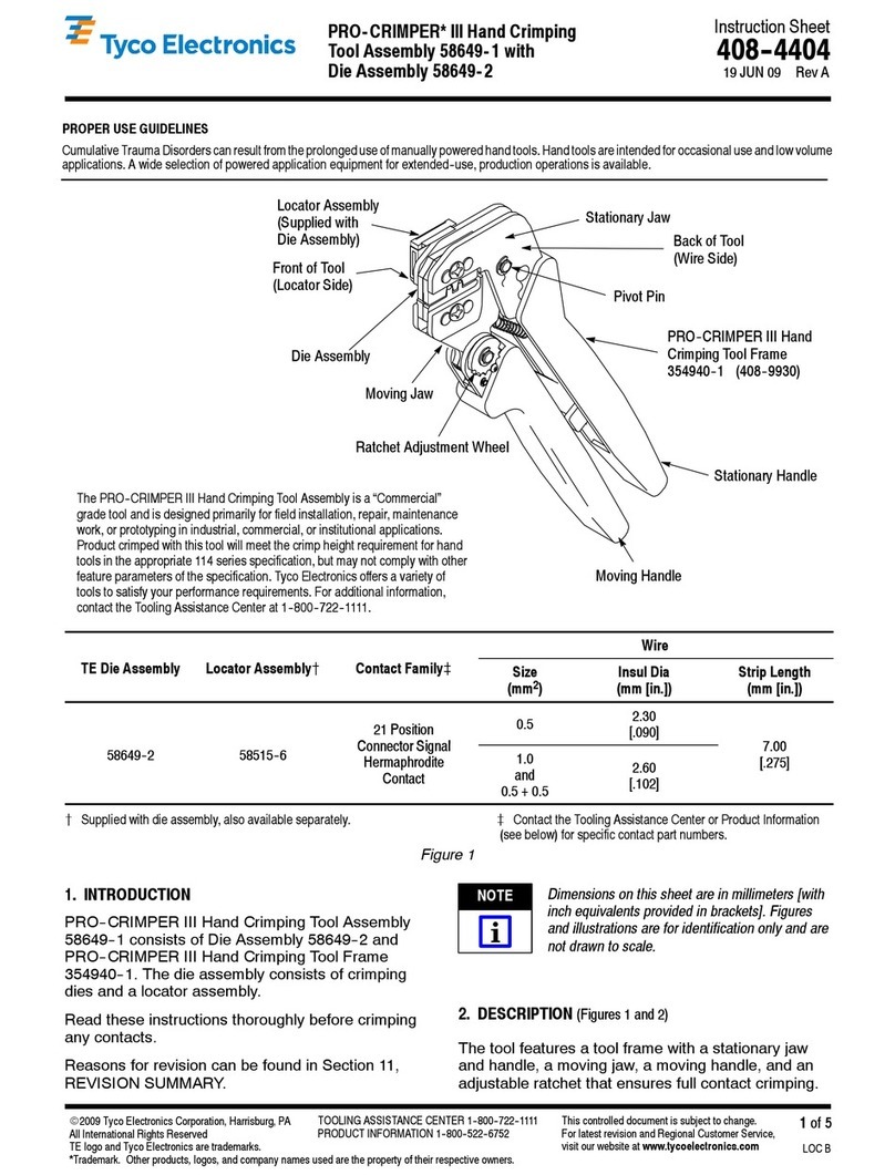
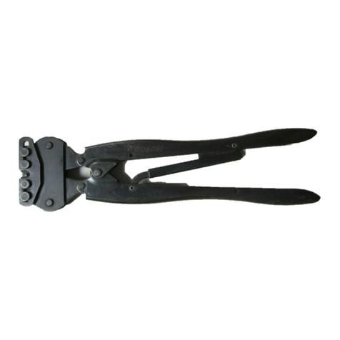
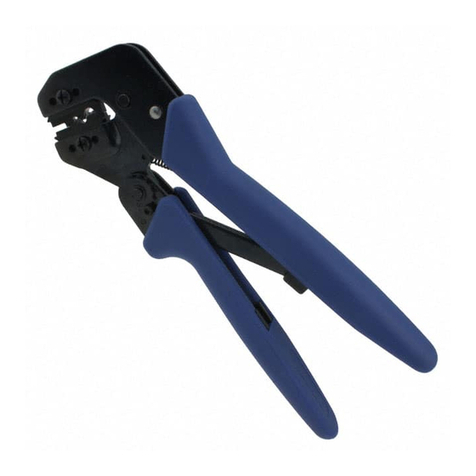
  9. Tyco Electronics 58425 Series User manual

Tyco Electronics 58425 Series User manual

This manual suits for next models

8

Other Tyco Electronics Crimping Tools manuals
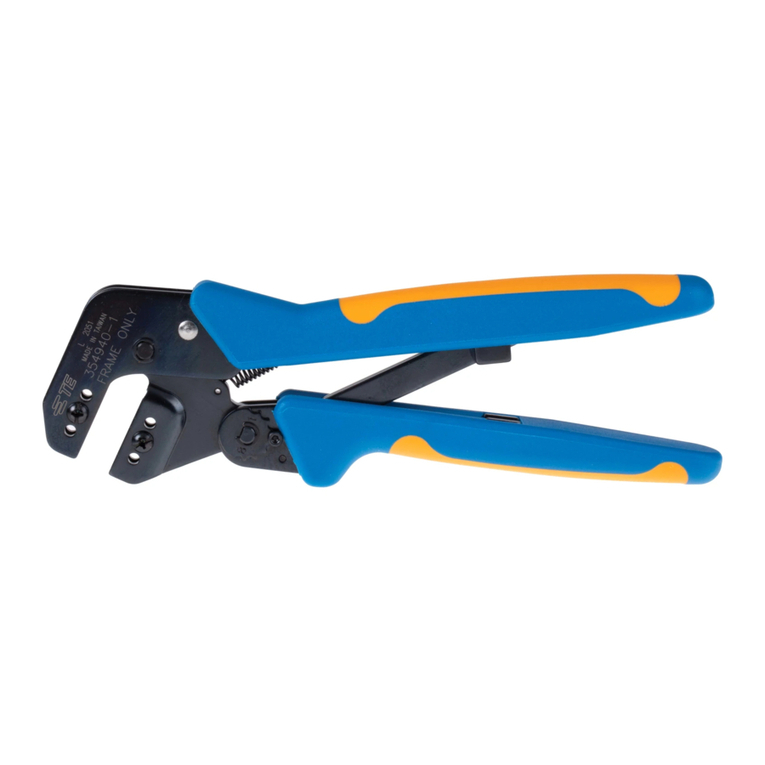
Tyco Electronics 2-1579004-9 User manual

Tyco Electronics

Tyco Electronics 2-1579004-9 User manual

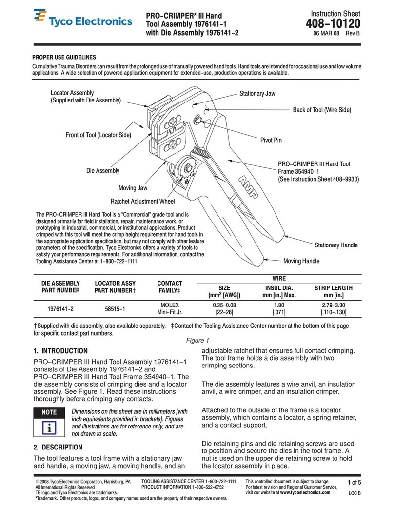
Tyco Electronics PRO-CRIMPER III User manual

Tyco Electronics

Tyco Electronics PRO-CRIMPER III User manual
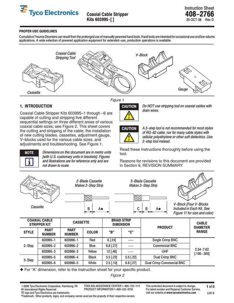
Tyco Electronics DYNA-CRIMP User manual

Tyco Electronics

Tyco Electronics DYNA-CRIMP User manual

Tyco Electronics ERGOCRIMP 3-1579001-5 User manual

Tyco Electronics

Tyco Electronics ERGOCRIMP 3-1579001-5 User manual

Tyco Electronics SDE PEW-12 User manual

Tyco Electronics

Tyco Electronics SDE PEW-12 User manual

Tyco Electronics 1490748-1 User manual

Tyco Electronics

Tyco Electronics 1490748-1 User manual

Tyco Electronics 1901820-1 User manual

Tyco Electronics

Tyco Electronics 1901820-1 User manual

Tyco Electronics 46121 User manual

Tyco Electronics

Tyco Electronics 46121 User manual

Tyco Electronics STRATO-THERM 1-46673-0 User manual

Tyco Electronics

Tyco Electronics STRATO-THERM 1-46673-0 User manual

Tyco Electronics PRO-CRIMPER III User manual

Tyco Electronics

Tyco Electronics PRO-CRIMPER III User manual

Tyco Electronics AMP SDE PEW 12 User manual

Tyco Electronics

Tyco Electronics AMP SDE PEW 12 User manual

Tyco Electronics ERGOCRIMP 6-1579001-5 User manual

Tyco Electronics

Tyco Electronics ERGOCRIMP 6-1579001-5 User manual

Tyco Electronics ERGOCRIMP 2-1579021-9 User manual

Tyco Electronics

Tyco Electronics ERGOCRIMP 2-1579021-9 User manual

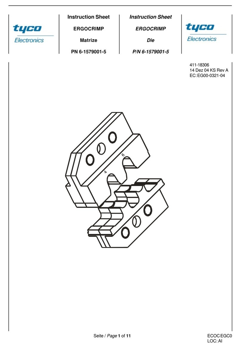
Tyco Electronics 603995 Series User manual
Tyco Electronics

Tyco Electronics 603995 Series User manual

Tyco Electronics PRO-CRIMPER III User manual

Tyco Electronics

Tyco Electronics PRO-CRIMPER III User manual

Tyco Electronics 2063195-1 User manual

Tyco Electronics

Tyco Electronics 2063195-1 User manual

Tyco Electronics 58569-1 User manual

Tyco Electronics

Tyco Electronics 58569-1 User manual

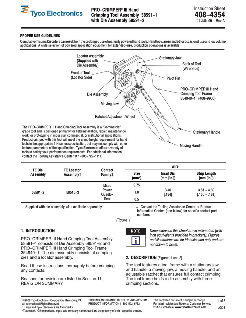
Tyco Electronics 58591-1 User manual

Tyco Electronics

Tyco Electronics 58591-1 User manual

Tyco Electronics PRO-CRIMPER III User manual
Tyco Electronics

Tyco Electronics PRO-CRIMPER III User manual
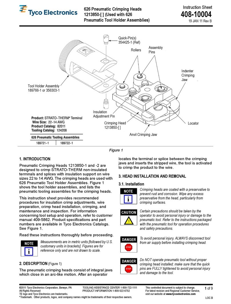
Tyco Electronics PRO-CRIMPER III User manual

Tyco Electronics

Tyco Electronics PRO-CRIMPER III User manual

Tyco Electronics PRO-CRIMPER III User manual

Tyco Electronics

Tyco Electronics PRO-CRIMPER III User manual

Tyco Electronics 696675-1 User manual

Tyco Electronics

Tyco Electronics 696675-1 User manual

Tyco Electronics 90430-1 User manual

Tyco Electronics

Tyco Electronics 90430-1 User manual

Tyco Electronics 58613-1 User manual

Tyco Electronics

Tyco Electronics 58613-1 User manual

Popular Crimping Tools manuals by other brands

TE Connectivity 2063528-1 instruction sheet

TE Connectivity

TE Connectivity 2063528-1 instruction sheet

molex 63825-3000 Specification sheet

molex

molex 63825-3000 Specification sheet

Elpress PVX611 manual

Elpress

Elpress PVX611 manual

CRH CRL CBLHCT1 instruction manual

CRH

CRH CRL CBLHCT1 instruction manual

Emerson Klauke MAPAX325CFM manual

Emerson

Emerson Klauke MAPAX325CFM manual

Emerson Klauke ES 105CFM manual

Emerson

Emerson Klauke ES 105CFM manual

KIMBALL MIDWEST 27-798 Operating instructions manual

KIMBALL MIDWEST

KIMBALL MIDWEST 27-798 Operating instructions manual

BGB 295060 Operation guide

BGB

BGB 295060 Operation guide

Danfoss ET4350 Operator's manual

Danfoss

Danfoss ET4350 Operator's manual

Milwaukee M18 Operator's manual

Milwaukee

Milwaukee M18 Operator's manual

HOGERT HT1P169 user manual

HOGERT

HOGERT HT1P169 user manual

Textron ESG105L instruction manual

Textron

Textron ESG105L instruction manual

Emerson Klauke ES 20RMCCFB manual

Emerson

Emerson Klauke ES 20RMCCFB manual

Continental Refrigerator PC150HD quick start guide

Continental Refrigerator

Continental Refrigerator PC150HD quick start guide

TE Connectivity ERGOCRIMP 1-1579001-3 instruction sheet

TE Connectivity

TE Connectivity ERGOCRIMP 1-1579001-3 instruction sheet

Emerson Klauke ES 105CFB manual

Emerson

Emerson Klauke ES 105CFB manual
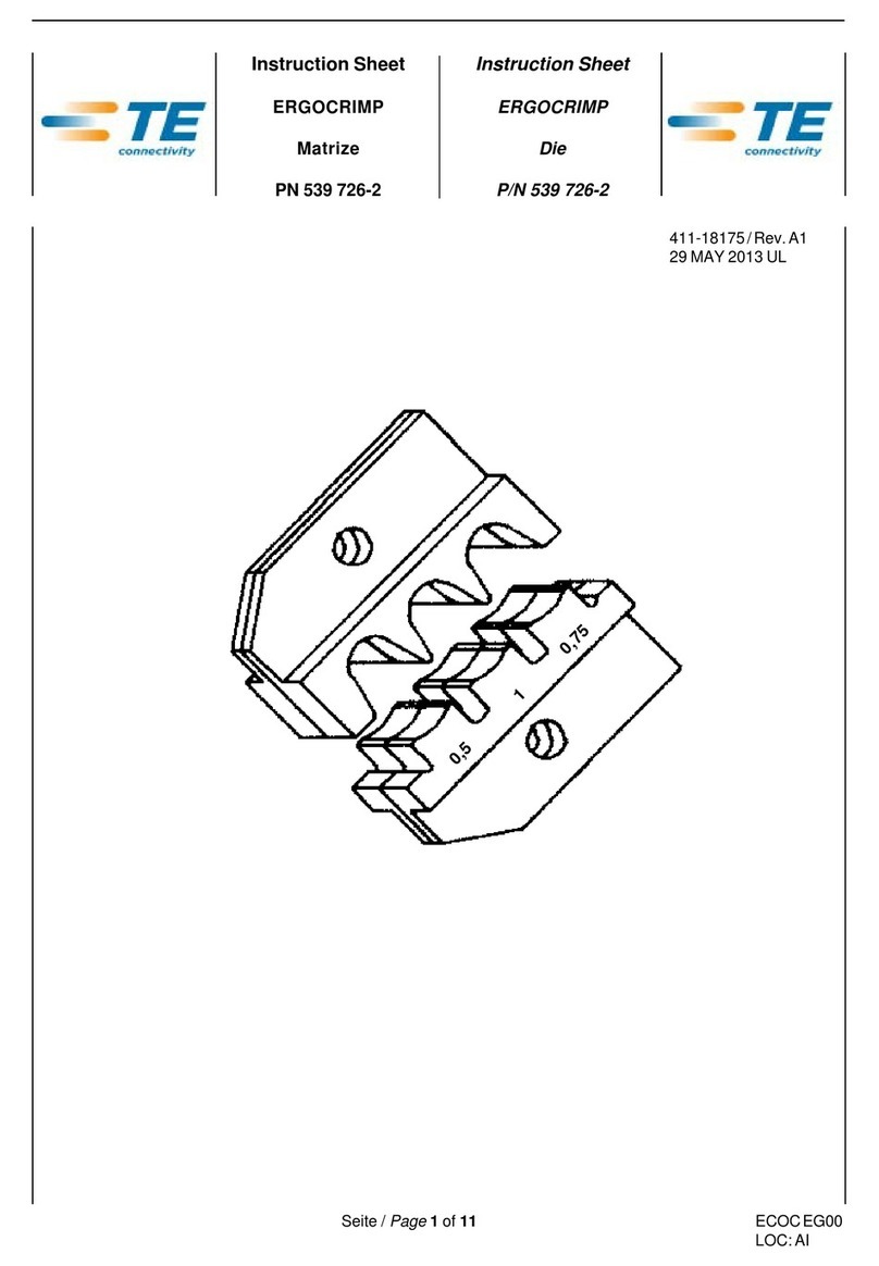
TE Connectivity 539 726-2 instruction sheet

TE Connectivity

TE Connectivity 539 726-2 instruction sheet

molex 207129 Series Specification sheet
molex

molex 207129 Series Specification sheet

manuals.online logo
manuals.online logoBrands
  • About & Mission
  • Contact us
  • Privacy Policy
  • Terms and Conditions

Copyright 2025 Manuals.Online. All Rights Reserved.

Instruction heet
75-Ohm Hex Crimp
Die Assem lies 408-9657
LOC B
1
of 3
E
2008 Tyco Electronics Corporation, Harrisburg, PA
All International Rights Reserved
TE logo and Tyco Electronics are trademarks.
*Trademark. Other products, logos, and company names used are the property of their respective owners.
TOOLING A I TANCE CENTER 1-800-722-1111
PRODUCT INFORMATION 1-800-522-6752 This controlled document is subject to change.
For latest revision and Regional Customer ervice,
visit our website at
www.tycoelectronics.com
07 MAR 08 Rev D
58425-[ ] and 58436-[ ]
PROPER USE GUIDELINES
CumulativeTraumaDisorderscanresultfromthe prolongeduseofmanually poweredhandtools.Hand toolsareintendedfor occasionaluseandlowvolume
applications. A wide selection of powered application equipment for extended-use, production operations is available.
Figure 1
tationary Jaw
Anvil Die
Indenter Die Moving Jaw
Hand Tool Frame
354940-1
Die Assemblies
58425-[ ] and 58436-[ ]
1. INTRODUCTION
This instruction sheet covers the use and
maintenance of Crimping Dies 58425–[ ] and
58436–[ ] (in their various configurations – denoted by
the dash number following the base part number),
used in PRO–CRIMPER* Hand Tool Frame
354940–1. The dies crimp 75–Ohm Hex Crimp BNC
and TNC plug connectors onto coaxial cable.
Reasons for reissue of this sheet are provided in
Section 7, REVISION SUMMARY.
All dimensions are in millimeters [with inches in
brackets]. Figures and illustrations are for
reference only and are not drawn to scale.
2. DESCRIPTION
(Figure 1)
Each die assembly consists of an indenter die and an
anvil die. When closed, the dies form either two or
three crimping chambers (depending on type) which
crimp the center contact and ferrule of the connector
onto the coaxial cable. Each die is held in the tool by
a single screw.
3. DIE INSTALLATION
1. Close the tool handles until the ratchet releases
and then allow them to open fully.
2. See Figure 1 for normal orientation of the dies.
Insert the dies inside the tool jaws and align the
retaining screw holes.
3. Thread the retaining screws into the holes and
carefully close the tool handles. Tighten the screws
with the appropriate hex wrench.
NOTE
i
408-9657
75-Ohm Hex Crimp Die Assemblies 58425-[ and 58436-[
Rev
D2
of 3 Tyco Elec ronics Corpora ion
Figure 2
Inser Cen er Con ac
in o Par ially Closed
Crimping Dies
Ferrule
(Ref)
Cen er Con ac
Slipped Over
Cen er Conduc or
4. CRIMPING PROCEDURE
4.1. Center Contact
1. Prepare the connector and the cable according
to the instructions packaged with the connector.
2. Slide the center contact onto the center
conductor of the cable; then insert the contact
assembly into the center contact crimp section of
the die. See Figure 2.
Make sure that the flange on the end of the
center contact butts against the crimping die. See
Figure 3.
3. Crimp the center contact by holding the cable in
place; then close the tool handles until the ratchet
releases.
4.2. Ferrule
1. Insert the crimped center contact into the
connector body until the cable dielectric butts
against the dielectric inside of the connector body.
The flared braid will then fit around the support
sleeve of the connector body.
2. Slide the ferrule forward over the braid until the
ferrule butts against the shoulder on the
connector body.
3. Place the ferrule on the appropriate anvil of the
die assembly so that the shoulder on the connector
body is butted against the die. See Figure 4.
4. Holding the assembly in place, close the tool
handles until the ratchet releases.
Figure 3
Flange on End
of Con ac
Crimping Die
Flange on End of Cen er
Con ac Bu s Agains Die
Damaged product should not be used. If a
damaged contact or ferrule is e ident, it should
be cut from the wire and replaced with a new
one. Do NOT reterminated contact or ferrules.
5. INSPECTION
5.1. Visual Inspection
Inspection of the crimping dies should be made on a
regular basis to ensure that they have not become
worn or damaged. Inspect the crimp sections for
flattened, chipped, worn, or broken areas. If damage
or abnormal wear is evident, the dies must be
replaced. Refer to Section 6, PARTS
REPLACEMENT.
Figure 4
Crimping Ferrule
Shoulder on
Connec or Body
Bu s Agains Die
Ferrule on Anvil
of Crimping Die
Typical RF
Connec or
(Ref)
Crimping Die
(Ref)
NOTE
i
CAUTION
!
408-9657
3
of 3Rev
D
Tyco E ectronics Corporation
A"
B" C"
Die 58425-[ ] Die 58436-[ ]
C"
B"
D"
DIE ASSEMBLY CHAMBER CRIMP DIMENSION +0.10 [.004]
PART NUMBER A" B" C" D"
58425-1 1.07 [.042] (Square) 5.41 [.213] (Hex) 6.48 [.255] (Hex) ---
58425-2 1.07 [.042] (Square) 3.25 [.128] (Hex) 4.52 [.178] (Hex) ---
58425-3 1.07 [.042] (Square) 3.84 [.151] (Hex) 8.23 [.324] (Hex) ---
58436-1 --- 5.41 [.213] (Hex) 6.48 [.255] (Hex) 1.73 [.068] (Hex)
58436-2 --- 2.54 [.100] (Hex) 8.23 [.324] (Hex) 1.73 [.068] (Hex)
58436-3 --- 3.84 [.151] (Hex) 4.52 [.178] (Hex) 1.73 [.068] (Hex)
58436-4 --- 3.73 [.147] (Hex) 4.52 [.178] (Hex) 1.73 [.068] (Hex)
Figure 5
5.2. Measuring Die Opening
The die assembly will perform correctly as long as:
(1) the product specified is correct for the application,
(2) the specific die assembly is used, (3) the die
assembly has been measured to ensure that the
openings are correct, and (4) the tool has been
adjusted correctly.
Figure 5 provides information on die opening sizes.
5.3. Ratchet Adjustment
The tool frame assembly ratchet mechanism features
an adjustment wheel with eight settings. The
adjustment wheel controls the amount of handle
pressure exerted on the tool jaws and crimping dies
during crimping. If the crimp is not acceptable, adjust
the ratchet as follows:
1. Sufficiently loosen the screw at the ratchet
adjustment wheel so that the wheel can be rotated
above the post that engages the teeth in the wheel.
2. If the crimp is too loose, turn the wheel to a
higher notch (for example, if the wheel is set at
notch no. 5, move the wheel to notch no. 6). If the
crimp is too tight, move the wheel to a lower notch.
3. Tighten the screw at the ratchet
adjustment wheel.
If the crimp cannot be made to conform to the
dimensions provided in the appropriate product
application specification, the tool and/or dies are
defective and must be replaced.
Other dies of the PRO-CRIMPER hand tool
series may be sed in this tool; however, the
ratchet adj stment wheel may req ire adj stment
to achieve acceptable crimp height.
6. PARTS REPLACEMENT
Customer–replaceable parts are shown in Figure 1.
Available separately, PRO–CRIMPER Repair Kit
679221–1 includes a variety of pins, rings, screws,
and springs. If the dies are damaged or worn
excessively, they must be replaced. Order the repair
kit and replaceable parts through your Tyco
Electronics Representative, or call 1–800–526–5142,
or send a facsimile of your purchase order to
1–717–986–7605, or write to:
CUSTOMER SERVICE (38–35)
TYCO ELECTRONICS CORPORATION
P.O. BOX 3608
HARRISBURG, PA 17105–3608
7. RE ISION SUMMARY
S
Updated logo and format.
NOTE
i