FOLSOM 2100DE Setup guide

Artisan Technology Group is your source for quality
new and certied-used/pre-owned equipment
• FAST SHIPPING AND
DELIVERY
• TENS OF THOUSANDS OF
IN-STOCK ITEMS
• EQUIPMENT DEMOS
• HUNDREDS OF
MANUFACTURERS
SUPPORTED
• LEASING/MONTHLY
RENTALS
• ITAR CERTIFIED
SECURE ASSET SOLUTIONS
SERVICE CENTER REPAIRS
Experienced engineers and technicians on staff
at our full-service, in-house repair center
WE BUY USED EQUIPMENT
Sell your excess, underutilized, and idle used equipment
We also offer credit for buy-backs and trade-ins
www.artisantg.com/WeBuyEquipment
REMOTE INSPECTION
Remotely inspect equipment before purchasing with
our interactive website at www.instraview.com
LOOKING FOR MORE INFORMATION?
Visit us on the web at www.artisantg.com for more
information on price quotations, drivers, technical
specications, manuals, and documentation
Contact us: (888) 88-SOURCE | sales@artisantg.com | www.artisantg.com
SM
View
Instra

INSTALLATION AND OPERATOR’S MANUAL
Model 2100DE
VFC-2100DE–Scaler with Digital Effects
Manual #26-6092936-00 / Revision A
Artisan Technology Group - Quality Instrumentation ... Guaranteed | (888) 88-SOURCE | www.artisantg.com

RECORD OF CHANGES
REV #
DATE
ECO #
DESCRIPTION
Approved By
A
5/2002
860
Release to Production
A.Y.
Manual # 26-6092936-00
Artisan Technology Group - Quality Instrumentation ... Guaranteed | (888) 88-SOURCE | www.artisantg.com

Operators Safety Summary
The general safety information in this summary is for operating personnel.
Do Not Remove Covers or Panels
There are no user-serviceable parts within the unit. Removal of the top
cover will expose dangerous voltages. To avoid personal injury, do not
remove the top cover. Do not operate the unit without the cover installed.
Power Source
This product is intended to operate from a power source that will not
apply more than 230 volts rms between the supply conductors or
between either supply conductor and ground. A protective ground
connection by way of grounding conductor in the power cord is essential
for safe operation.
Grounding the Product
This product is grounded through the grounding conductor of the power
cord. To avoid electrical shock, plug the power cord into a properly wired
receptacle before connecting to the product input or output terminals. A
protective-ground connection by way of the grounding conductor in the
power cord is essential for safe operation.
Use the Proper Power Cord
Use only the power cord and connector specified for your product. Use
only a power cord that is in good condition. Refer cord and connector
changes to qualified service personnel.
Use the Proper Fuse
To avoid fire hazard, use only the fuse having identical type, voltage
rating, and current rating characteristics. Refer fuse replacement to
qualified service personnel.
Do Not Operate in Explosive Atmospheres
To avoid explosion, do not operate this product in an explosive
atmosphere.
The rear panel ON/OFF switch does not disconnect the unit from input
AC power. To facilitate disconnection of AC power, the power cord must
be connected to an accessible outlet near the unit. Building Branch Circuit
Protection: For 115 V use 20 A, for 230 V use 8 A.
When the VFC-2100DE is used in the 230-volt mode, a UL listed line cord
rated for 250 volts at 15 amps must be used and must conform to IEC-
227 and IEC-245 standards. This cord will be fitted with a tandem prong-
type plug.
WARNING
WARNING
Terms In This Manual
Highlights an operating procedure, practice,
condition, statement, etc., which, if not strictly
observed, could result in injury to or death of
personnel.
NOTE Highlights an essential operating procedure,
condition, or statement.
The exclamation point within an equilateral triangle is
intended to alert the user to the presence of
important operating and maintenance (servicing)
instructions in the literature accompanying the
appliance.
WARNING
CAUTION
Le point d´exclamation dans un triangle
equilatéral signale à alerter l´utilisateur qu´il
y a des instructions d´operation et
d´entretien tres importantes dans la
litérature qui accompagne l´appareil.
ein Ausrufungszeichen innerhalb eines
gleichwinkeligen Dreiecks dient dazu, den
Benutzer auf wichtige Bedienungs-und
Wartungsanweisungen in der Dem Great
beiliegenden Literatur aufmerksam zu
machen.
AVERTISSEMENT!
VORSICHT
Terms As Marked on Equipment
Highlights an operating procedure, practice, condition, statement, etc., which, if not strictly observed, could result in injury
to or death of personnel.
The exclamation point within an equilateral triangle is intended to alert the user to the presence of important operating
and maintenance (servicing) instructions in the literature accompanying the appliance.
Le point d´exclamation dans un triangle equilatéral signale à alerter l´utilisateur qu´il y a des instructions d´operation et
d´entretien tres importantes dans la litérature qui accompagne l´appareil.
ein Ausrufungszeichen innerhalb eines gleichwinkeligen Dreiecks dient dazu, den Benutzer auf wichtige Bedienungs-und
Wartungsanweisungen in der Dem Great beiliegenden Literatur aufmerksam zu machen.
NOTE This equipment has been tested and found to comply with the limits for a Class A digital device, pursuant to Part 15 of the FCC Rules. These
limits are designed to provide reasonable protection against harmful interference when the equipment is operated in a commercial environment. This
equipment generates, uses, and can radiate radio frequency energy and, if not installed and used in accordance with the instruction manual, may
cause harmful interference to radio communications. Operation of this equipment in a residential area is likely to cause harmful interference, in which
case the user will be required to correct the interference at the user’s own expense.
CAUTION
AVERTISSEMENT!
VORSICHT
WARNING
Artisan Technology Group - Quality Instrumentation ... Guaranteed | (888) 88-SOURCE | www.artisantg.com

Artisan Technology Group - Quality Instrumentation ... Guaranteed | (888) 88-SOURCE | www.artisantg.com

Manual # 26-6092936-00 / Revision A VFC-2100DE –Scaler with Digital Effects i
Table of Contents
CHAPTER ONE............................................................................................................................................1
Introduction .................................................................................................................................................1
About the VFC-2100DE.........................................................................................................................................3
Features.................................................................................................................................................................3
Technical Description...........................................................................................................................................4
CHAPTER TWO ...........................................................................................................................................5
Installation ...................................................................................................................................................5
Rack-Mount Installation........................................................................................................................................6
Power Cord/Line Voltage Selection.....................................................................................................................6
Video Input Connections......................................................................................................................................7
Video Output Connections...................................................................................................................................7
CHAPTER THREE........................................................................................................................................9
Operation .....................................................................................................................................................9
Menu Operation...................................................................................................................................................10
Main Menu Operation .........................................................................................................................................11
Video Input Configuration Menu........................................................................................................................11
Input Configuration Save/Recall Menu .........................................................................................................11
Recall Input Configuration.............................................................................................................................12
Save Current Input Configuration.................................................................................................................12
Delete Input Configuration.............................................................................................................................13
Edit Input Configuration.................................................................................................................................13
Reacquire Input...............................................................................................................................................14
Input Raster Size / Position Menu .....................................................................................................................14
Left and Right Edge, Top and Bottom Adjustments....................................................................................14
Input Aspect Ratio..........................................................................................................................................14
Reset Input Size / Position Adjustments......................................................................................................15
Input Levels / Color Space Adjustment Menu..................................................................................................15
Input Contrast / Brightness Adjustment.......................................................................................................15
Input Color Space...........................................................................................................................................15
Input RGB Color Balance...............................................................................................................................16
Input RGB Color Balance Reset....................................................................................................................16
Input NON-RGB Color Balance......................................................................................................................16
Input Motion Filtering Menu...............................................................................................................................16
Horizontal and Vertical Filter Correction......................................................................................................17
Freeze Input Image .........................................................................................................................................17
Output Configuration Menu ...............................................................................................................................17
Output Save / Recall Menu.............................................................................................................................17
Recall Output User Configuration.................................................................................................................17
Save Current Output Configuration..............................................................................................................19
Delete Output Configuration..........................................................................................................................19
Edit Output Configuration..............................................................................................................................20
Output Position...............................................................................................................................................21
Sync Type........................................................................................................................................................21
Output Levels/Gamma Menu .........................................................................................................................21
Color Space.....................................................................................................................................................21
Color Balance..................................................................................................................................................22
Gamma Correction Menu...............................................................................................................................22
Genlock Menu.................................................................................................................................................22
Genlock Control............................................................................................................................................22
Horizontal Phase..........................................................................................................................................23
Output Test Pattern........................................................................................................................................23
Output Test Pattern Mode ............................................................................................................................23
Output Test Pattern Type.............................................................................................................................23
Inverting Output Test Pattern .......................................................................................................................23
Grid Test Pattern..........................................................................................................................................23
Raster Test Pattern Box...............................................................................................................................23
Zoom/Pan Menu..............................................................................................................................................24
Zoom............................................................................................................................................................24
Horizontal Center .........................................................................................................................................24
Artisan Technology Group - Quality Instrumentation ... Guaranteed | (888) 88-SOURCE | www.artisantg.com

Vertical Center..............................................................................................................................................24
Zoom/Pan Reset ..........................................................................................................................................24
Special Functions Menu.....................................................................................................................................24
Serial Mode .....................................................................................................................................................25
Serial Submenu...............................................................................................................................................25
RS-232 Port Menu...........................................................................................................................................25
RS-485 Port Menu...........................................................................................................................................25
Sync Submenu................................................................................................................................................26
Autosync Status ...........................................................................................................................................26
Sync Messages............................................................................................................................................26
Loss of Video Signal Configuration..............................................................................................................26
Field Extend Option........................................................................................................................................26
Analog Mixer Option.......................................................................................................................................26
Video Contrast / Brightness Adjustment.......................................................................................................27
Technical Support Menu................................................................................................................................27
Video Messages..................................................................................................................................................27
Video Error......................................................................................................................................................27
Internal Error #2..............................................................................................................................................27
Internal Error #3..............................................................................................................................................28
Factory Reset......................................................................................................................................................28
CHAPTER FOUR........................................................................................................................................29
RS-232 & RS-485 Interface Control .........................................................................................................29
RS-232 and RS-485 Connector Pinout/Interface Signal Definition .................................................................30
Serial Control Rear Panel Connector Signal Definition...................................................................................30
Serial Port Configuration Instructions..............................................................................................................30
RS-232 Command Format Definition.................................................................................................................30
Command Format...........................................................................................................................................30
VFC-2100DE’s Prompts and Responses ......................................................................................................31
Power-up Banner............................................................................................................................................31
RS-485 Command Format Definition.................................................................................................................31
CHAPTER FIVE..........................................................................................................................................33
VFC-2100DE Commands ..........................................................................................................................33
Additional Notes for Application Programmers.............................................................................................35
VFC-2100DE Commands Description ...............................................................................................................36
CHAPTER SIX............................................................................................................................................51
Folsom Research Information .................................................................................................................51
Folsom Research Warranty................................................................................................................................52
Return Material Authorization (RMA) ................................................................................................................52
Folsom Research Contact Information.............................................................................................................52
APPENDIX..................................................................................................................................................53
Technical Specifications..........................................................................................................................53
Inputs...................................................................................................................................................................54
Outputs................................................................................................................................................................54
Mechanical...........................................................................................................................................................54
Connectors..........................................................................................................................................................54
Artisan Technology Group - Quality Instrumentation ... Guaranteed | (888) 88-SOURCE | www.artisantg.com
Manual # 26-6092935-00 / Revision A VFC-2100DE –Scaler with Digital Effects 1
1
CHAPTER ONE
Introduction
What you will find in this chapter…
About the VFC-2100DE
Features
Technical Description
Artisan Technology Group - Quality Instrumentation ... Guaranteed | (888) 88-SOURCE | www.artisantg.com

Artisan Technology Group - Quality Instrumentation ... Guaranteed | (888) 88-SOURCE | www.artisantg.com

2 VFC-2100DE –Scaler with Digital Effects Manual # 26-6092936-00 / Revision A
Introduction
About the VFC-2100DE
The VFC-2100DE can be used whenever it is necessary to convert high-resolution video from one format to another
or to edge-blend high-resolution computer-generated images. Typical applications include:
Conversion of high-resolution computer-generated signals to alternate user-defined output formats such as
875-line (RS-343A) format for simulation and training applications.
Interlaced-to-non-interlaced and non-interlaced-to-interlaced format conversion.
Continuous real-time image pan and zoom to support applications such as head-tracked displays.
Edge-blending to support seamless multi-screen presentations.
The VFC-2100DE allows the user to control all aspects of the scan conversion process via user-friendly front panel
menus or remotely through the serial control interface that can be configured for RS-232 or RS-485 operation.
Examples of the type of control provided include continuous pan and zoom capability to permit conversion of areas of
interest in the source video and adjustable horizontal and vertical filters. The unit can store up to ninety-six user-
specified configurations in nonvolatile memory for subsequent recall.
Attention to the Installation and Operation Sections of the manual is important to ensure trouble-free operation.
Should you have any questions regarding the operation of this unit, please consult the factory.
Features
The VFC-2100DE provides and offers the following features:
Automatically locks to RGB video sources with resolutions up to 2048 x 1280.
User-programmable RGB output supports resolutions up to 1280 x 1024.
Supports input and output of interlaced or noninterlaced video.
Supports user-defined output window size and location or full screen output.
Fully programmable, smooth "camera like" pan and zoom functions.
Image resizing via proprietary digital signal processing techniques.
User-friendly front panel interface.
Reconfigurable RS-232 or RS-485 serial port supports real-time control of image processing functions with
low latency.
Nonvolatile storage of configuration data.
Built-in test pattern generator.
User-programmable edge-blending supports seamless multi-screen presentations.
Artisan Technology Group - Quality Instrumentation ... Guaranteed | (888) 88-SOURCE | www.artisantg.com
4 VFC-2100DE –Scaler with Digital Effects Manual # 26-6092936-00 / Revision A
Technical Description
The VFC-2100DE Video Format Converter automatically locks to interlaced and non-interlaced videos with horizontal
scan rates up to 95 kHz. The video scaler supports conversion of videos with resolutions up to 2048 x 1280. The unit
processes the incoming video to derive an RGB output image in the video format selected by the operator. Output
video timing parameters are user-programmable. Both interlaced and non-interlaced video output formats with
resolutions up to 1280 x 1024 are fully supported.
The VFC-2100DE supports continuous pan and zoom functions. The operator selects the portion of the input image
to be processed. This input area of interest may consist of the full image or a selected input "window". The video
within the input area of interest may be rescaled to fill a selected output window or the entire output display. Pan and
zoom parameters are fully programmable and are entered in single-pixel increments to support smooth real-time pan
and zoom operations.
The VFC-2100DE is controlled via user-friendly front panel menus or in real time using a serial control link. The user
can control all aspects of the scaling process through either of these interfaces..
Artisan Technology Group - Quality Instrumentation ... Guaranteed | (888) 88-SOURCE | www.artisantg.com
Manual # 26-6092936-00 / Revision A VFC-2100DE –Scaler with Digital Effects 5
2
CHAPTER TWO
Installation
What you will find in this chapter…
Line Voltage Selection
Video Input Connections
Video Output Connections
Artisan Technology Group - Quality Instrumentation ... Guaranteed | (888) 88-SOURCE | www.artisantg.com

6 VFC-2100DE –Scaler with Digital Effects Manual # 26-6092936-00 / Revision A
Installation
NOTE: Front Panel features are shown on page 14
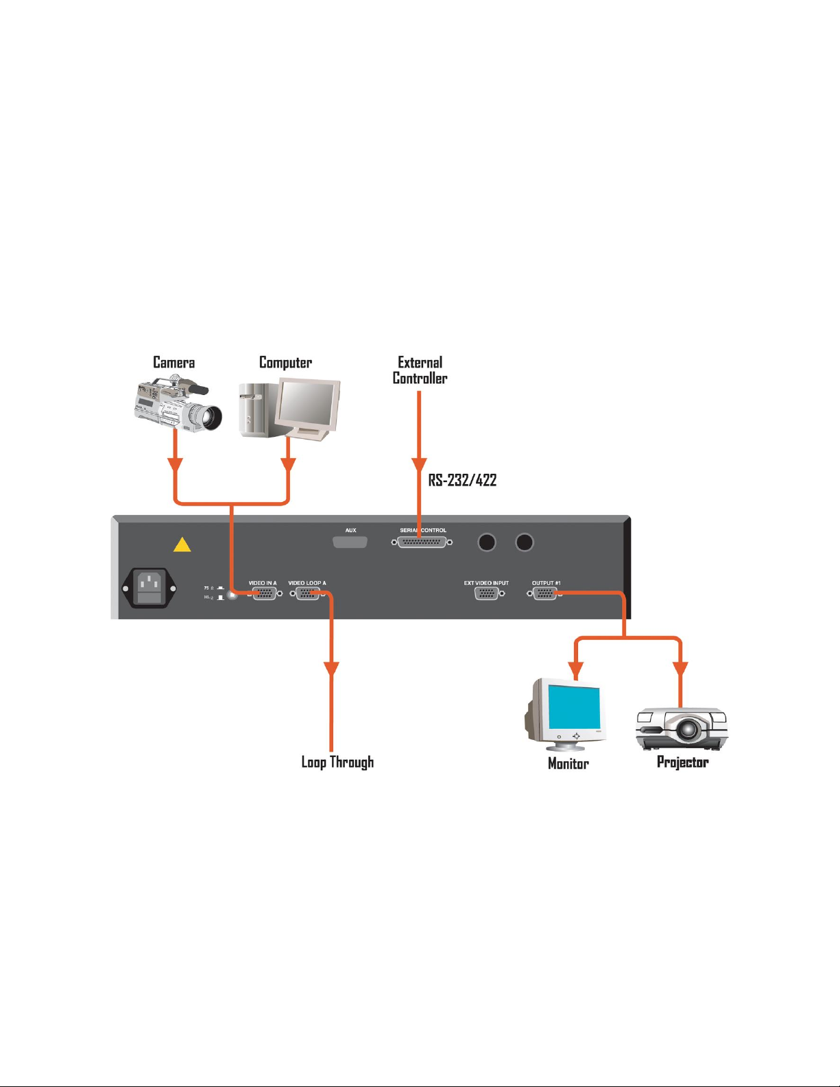
Figure 2-1: VFC-2100DE Rear Panel
Rear Panel Connectors:
AC Power connector
Video Input HD-15 connectors
Video Output HD-15 connectors
Serial Control Connector
All video connections must be made with VGA cables
Rack-Mount Installation
VFC-2100DE units are designed to be rack mounted and are supplied with front rack-mount hardware. Rear rack-
mount brackets are available as a kit and are recommended for use when units are mounted in transit cases. When
rack mounting the unit, remember that the maximum ambient operating temperature for the unit is 40 degrees C.
Leave at least one inch of space front and rear to make sure that the airflow through the fan and vent holes is not
restricted. When installing equipment into a rack, distribute the units evenly to prevent hazardous conditions that may
be created by uneven weight distribution. Connect the unit only to a properly rated supply circuit. Reliable grounding
(earthing) of rack-mounted equipment should be maintained.
Power Cord/Line Voltage Selection
VFC-2100DE is rated to operate with the following supplies:
Input Power: 115-230 VAC, 47-63 Hz
Power Consumption : 125 watts maximum
The VFC-2100DE performs line voltage selection automatically. No user controls are required for line voltage
selection.
When the VFC-2100DE is used with 230-volt supplies, a UL listed line cord rated for 250 volts at 15
amps must be used. This cord will be fitted with a tandem prong-type plug.
Tandem Plug
La choix de la ligne de voltage se realize automatiquement par I’VFC-2100DE Transformateur
Graphique On n’apas besoin du controller usager pour la choix de la ligne de voltage.
Das VFC-2100DE-Gerät mu beim Anschlu an 240V ~ mit einer vom VDE auf 250V/10A geprüften
Netzleitung mit einem Schukostecker ausgestattet sein.
WARNING
AVERTISSEMENT!
VORSICHT
Artisan Technology Group - Quality Instrumentation ... Guaranteed | (888) 88-SOURCE | www.artisantg.com

Manual # 26-6092936-00 / Revision A VFC-2100DE –Scaler with Digital Effects 7
Video Input Connections
The video input section on the VFC-2100DE rear panel contains one pair of 15-pin SUB-D input connectors.
1) If you are using a PC with a 15-pin VGA connector, connect the video output of the PC to the 15-pin SUB-D
connector input labeled “Video In A” on the VFC-2100DE rear panel.
2) If video inputs will be looped through the VFC-2100DE to a high resolution graphics monitor, connect the
input of the VGA monitor to the 15-pin SUB-D connector input labeled “Video Loop A” on the VFC-2100DE
rear panel.
3) You will need to select the input port and termination via the VFC-2100DE rear panel switch. It is important
to have the termination set correctly for each installation. If the termination is not set correctly, the unit may
not work properly. Generally, the VFC-2100DE is installed between the computer workstation and the
computer monitor. In this case, the termination setting should be set to HI-Z. Monitors typically either have
built-in 75-ohm termination or have a provision to terminate or un-terminate at the monitor via switches or a
BNC loop-through. Termination should always be at the end of the video chain.
Video Output Connections
RGB Video Output: Connect the output device to Output #1 on the output section of the VFC-2100DE rear panel.
Select the desired output format via the front panel menus or serial link.
Artisan Technology Group - Quality Instrumentation ... Guaranteed | (888) 88-SOURCE | www.artisantg.com

Artisan Technology Group - Quality Instrumentation ... Guaranteed | (888) 88-SOURCE | www.artisantg.com

Manual # 26-6092936-00 / Revision A VFC-2100DE –Scaler with Digital Effects 9
3
CHAPTER THREE
Operation
What you will find in this chapter…
Main Menu Operation
Video Input Configuration Menu
Input Raster Size/Position Menu
Input Levels/Color Space Adjustment Menu
Output Configuration Menu
Zoom/Pan Menu
Mixer Control Menu
Special Functions Menu
Video Messages
Factory Reset
Artisan Technology Group - Quality Instrumentation ... Guaranteed | (888) 88-SOURCE | www.artisantg.com

10 VFC-2100DE –Scaler with Digital Effects Manual # 26-6092936-00 / Revision A
Operation
After connecting the VFC-2100DE to the graphics workstation and the desired video output device as described in
the prior sections, plug the unit into the designated AC power source. Locate the power switch on the front panel and
turn the VFC-2100DE on.
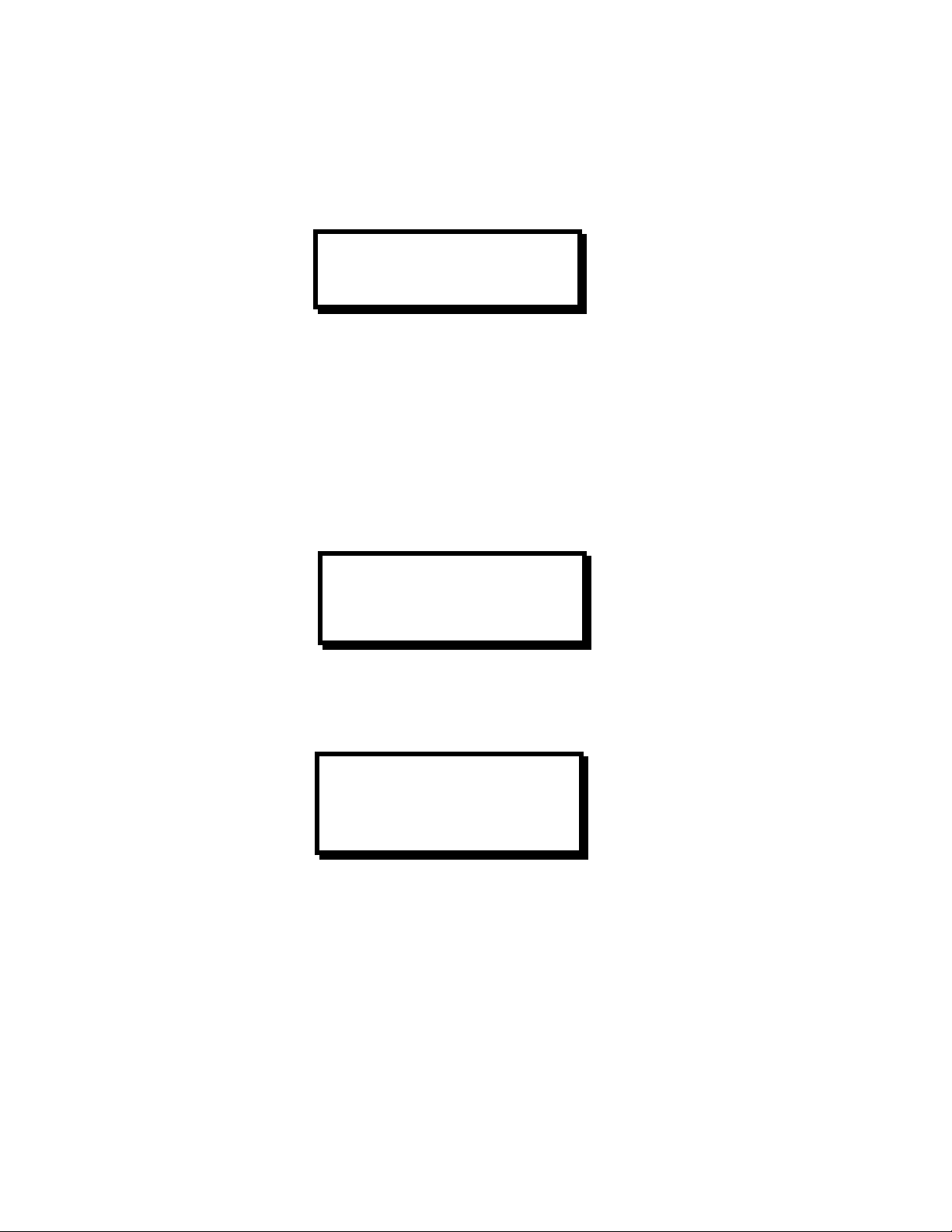
The display shown below will appear for one to two seconds on VFC-2100DE LCD display. Note that the revision
number displayed will reflect the revision of the currently installed software.
While the VFC-2100DE is initializing, the following display will be shown.
When the initialization is complete, the Main Menu will be displayed.
If the VFC-2100DE does not detect or recognize video on an input port, it will display the VIDEO ERROR Menu (see
page 27). Press any key to clear the error message.
Menu Operation
The VFC-2100DE is controlled via a 4 x 20 LCD display and six control keys: Menu Up (MENU
), Menu Down
(MENU
), Item Up (ITEM
), Item Down (ITEM
), ON/+, and OFF/-. The Menu key allows the user to cycle through
the VFC-2100DE menus. When the last menu is reached and the Menu key is pressed, the VFC-2100DE will return
to the first menu. Each menu contains 1 to 17 fields, which can be selected and edited by the user. The selected field
will be bracketed by < >. By pressing the ITEM
and ITEM
keys, the user can move the brackets to the other fields
in the menu. The ON/+ and OFF/- keys allow the user to toggle on and off or increment and decrement the selected
field as well as descend into other sub-menus.
FOLSOM RESEARCH INC.
2100 VFC –XXX.XX.X
VIDEO
FORMAT CONVERTER
FOLSOM RESEARCH INC.
2100 VFC –XXX.XX.X
INITIALIZING
PLEASE WAIT...
VFC 2100
F
R IN A:<##-AAAAAAAA>
T
POUT: <##-AAAAAAAA>
Artisan Technology Group - Quality Instrumentation ... Guaranteed | (888) 88-SOURCE | www.artisantg.com

Manual # 26-6092936-00 / Revision A VFC-2100DE –Scaler with Digital Effects 11
Main Menu Operation
The main menu for the VFC-2100DE conveys information concerning both the input and output video. The letters “F
R”
will appear before the IN A field if the input video is currently in Freeze Mode. If the letters “T
P” appear next to the
OUT field then the Test pattern is enabled.
Within the IN A and OUT fields, the letters FC, XX or a number between 1 and 96 will be displayed before the
configuration name. This indicates which configuration is currently being used, where FC stands for “Factory
Configuration”. If an asterisk “*” appears between the configuration number and the video description, then the
current configuration has been modified without that modification having been saved. When “XX” shows before the
configuration name, then the user has deleted a configuration from the input or output library while the configuration
is in use. While this is a valid operation, the “XX” is indicating that the current configuration is not available for recall
should the user modify its parameters.
Pressing the ON/+ or OFF/- key while the IN A field is bracketed will bring the user to the Input Configuration Scaler
Menu. If the ON/+ or OFF/- key is pressed when the OUT field is bracketed, the user will be brought to the Output
Configuration Menu (see section 6.3.2).
Video Input Configuration Menu
This menu is used to configure the input video source for IN A or IN B. In the top right corner of the display, the letter
Aor Bwill be displayed. Pressing the ON/+ or OFF/- key while the brackets are around the Aor Bwill allow the user
to select which input video source is currently being modified, saved or recalled. In addition, the four Input
Configuration sub-menus shown above also allows the user to change which input video source is being modified, by
following the procedure described above.
Input Configuration Save/Recall Menu
VFC 2100
F
RIN: <##-AAAAAAAA>
T
POUT: <##-AAAAAAAA>
INPUT CFG. SCLR <X>
SAVE/RECALL <+>
RASTER SIZE/POS <+>
LEVELS/CSC <+>
FILTERING <+>
FREEZE <AAA>
SYNC SELECT <N/A>
AUTO SYNC ONCE <N/A>
SAVE/RECALL SCLR <A>
CURR CFG <AAAAAAAA>
SAVE CURR CFG <+>
DELETE A CFG <+>
EDIT PARAMS <+>
REACQUIRE INPUT <+>
Artisan Technology Group - Quality Instrumentation ... Guaranteed | (888) 88-SOURCE | www.artisantg.com
12 VFC-2100DE –Scaler with Digital Effects Manual # 26-6092936-00 / Revision A
Using this menu, the user can save, recall, delete and edit user configuration files. The VFC-2100DE can store 96
user configurations. The CURR CFG field tells the user which input configuration is currently being used.
Recall Input Configuration
By pressing the ON/+ key while the brackets are around the CURR CFG field, the user has the option of choosing a
saved input configuration for recall. If AutoSync (see page 26) is on, then the user will only see those saved
configurations that match the current timing parameters connected to the system. In order to see the entire list of
saved configurations, the Autosync feature must be turned off.
Using the ON/+ or OFF/- keys when the CFG field is bracketed, the VFC-2100DE will scroll through the saved
configurations. Once a configuration has been chosen and the RECALL field has been selected, pressing the ON/+
key will recall the configuration for immediate use by the system. If there are no configurations in the user library that
match the timing of source currently connected to the system or if the user library is empty, the message shown
below will be displayed upon trying to enter the Recall Menu.
Save Current Input Configuration
This menu allows the user to save an input video. When the ## field is bracketed, the user can choose a
configuration number between 1 and 96 by pressing the ON/+ or OFF/- keys. The AAAAAAAA field is a comment
field, which can contain an alphanumeric description of the input video. When this field has brackets around it, the
Item Up (ITEM
) and Item Down (ITEM
)keys will move the cursor within the field. Once the cursor is in the desired
location, pressing the ON/+ or OFF/- keys will allow the user to scroll through the alphanumeric characters available.
The character set is comprised of 1 - 9 and A –Z.
The VFC-2100DE distinguishes configurations only by the configuration number; therefore various saved
configurations can have the same description. Once the configuration number and description have been entered,
make sure the brackets are around the SAVE field and then press the ON/+ key on the front panel to save the
configuration. When the configuration has been saved the VFC-2100DE will return to the previous menu and the
CURR CFG field will show the description of the saved configuration.
RECALL INPUT CFG. <x>
CFG <AAAAAAAA>
RECALL <+>
NO MATCHES FOUND
IN USER LIBRARY
ANY KEY CONTINUES
SAVE INPUT CFG. <x>
ITEM = Position
FUNCTION = Char
<##><AAAAAAAA><SAVE>
Artisan Technology Group - Quality Instrumentation ... Guaranteed | (888) 88-SOURCE | www.artisantg.com

Manual # 26-6092936-00 / Revision A VFC-2100DE –Scaler with Digital Effects 13
Delete Input Configuration
When the VFC-2100DE is displaying this menu, the user has the option of choosing a saved input configuration for
deletion. By pressing the ON/+ or OFF/- keys when the FORMAT field is bracketed, the VFC-2100DE will scroll
through the user library. Once a configuration has been chosen and the DELETE field has been selected, pressing
the ON/+ key will permanently delete the configuration from the system. If there are no configurations in the user
library, the message shown below will be displayed upon trying to enter the Delete Menu.
Edit Input Configuration
This menu is used to adjust the input video parameters. If anything within this menu is modified, the user must put the
brackets around the “+” in the APPLY field and press the ON/+ key for the change to take effect.
The Horizontal and Vertical parameters can be adjusted to match the incoming video sent to the VFC unit. Those
fields shown above with square brackets are not adjustable. Horizontal and Vertical frequencies are display in units of
Hertz. H TOTAL, ACTIVE and FP (Front Porch) are shown in units of pixels while the vertical equivalents are in units
of lines. The INTERLACED field will show NON for non-interlaced video and 2:1 for interlaced video. VID LEVEL is in
units of mV and should be adjusted to match the source level going into the system. PEDESTAL is in units of mV and
should be adjusted to match the pedestal level on the source video signal.
DEL INPUT CFG. <x>
DELETE <+>
USER LIBRARY EMPTY
ANY KEY CONTINUES
EDIT INPUT
H FREQ [#####]
H TOTAL <####>
H ACTIVE <####>
H FP <###>
V FREQ [#####]
V TOTAL [####]
V ACTIVE <####>
V FP <##>
INTERLACED [AAA]
VID LEVEL <###>
PEDESTAL <###>
CLAMP GATE <####>
AR <#.###>
RESET <+>
Artisan Technology Group - Quality Instrumentation ... Guaranteed | (888) 88-SOURCE | www.artisantg.com
This manual suits for next models
1
Table of contents
Other FOLSOM Media Converter manuals


