Fona MyCrown Design User manual
jó`êçïå=aÉëáÖå
pÉêîáÅÉ=j~åì~ä båÖäáëÜ
Service manual,

2
MyCrown Design
Table of contents
1General information.................................................................................................. 4
1.1 Structure of the document............................................................................. 4
1.1.1 Identification of the danger levels..................................................... 4
1.1.2 Formats and symbols used .............................................................. 5
1.2 Safety ............................................................................................................ 5
1.2.1 Basic safety information ................................................................... 5
1.2.1.1 Prerequisites ..................................................................... 5
1.2.1.2 Modifications to the product .............................................. 5
1.2.1.3 Movement and stability of the unit..................................... 6
1.2.1.4 Maintenance and repair..................................................... 6
1.2.1.5 Accessories ....................................................................... 6
1.2.2 Safety labels..................................................................................... 7
1.2.3 Electrostatic charge.......................................................................... 8
1.2.3.1 ESD protective measures.................................................. 8
1.2.3.2 About the physics of electrostatic charges ........................ 8
1.2.4 Radio interference............................................................................ 9
1.3 General information....................................................................................... 10
1.4 Additional information.................................................................................... 11
2Installation ................................................................................................................ 12
2.1 Preparing the cart.......................................................................................... 12
2.2 Preparing the controller................................................................................. 14
2.3 Mounting the control panel............................................................................ 15
2.4 Installing the controller .................................................................................. 17
2.5 Connecting the cables................................................................................... 18
2.6 Attaching the cover ....................................................................................... 21
2.7 Testing electrical safety................................................................................. 22
3Troubleshooting........................................................................................................ 23
4Repair....................................................................................................................... 24
4.1 General information on repair ....................................................................... 24
4.2 Replacing Wi-Fi antennas ............................................................................. 24
4.3 Replacing the back panel.............................................................................. 25
4.4 Attaching/removing the controller.................................................................. 26
4.4.1 Dismantling the controller................................................................. 26
4.4.1.1 Disconnecting the cables .................................................. 26
4.4.1.2 Removing the controller .................................................... 29

Service Manual
båÖäáëÜ
cê~å´~áë
3
4.4.2 Installing the controller .................................................................... 30
4.4.2.1 Preparing the controller .................................................... 30
4.4.2.2 Installing the controller...................................................... 31
4.4.2.3 Connecting the cables...................................................... 32
4.4.2.4 Attaching the cover........................................................... 35
4.5 Replacing the hard disk................................................................................ 36
4.5.1 Removing the back panel................................................................ 36
4.5.2 Dismantling the hard disk................................................................ 36
4.5.3 Installing the hard disk..................................................................... 37
4.5.4 Mounting the back panel ................................................................. 38
4.6 Replacing the handles.................................................................................. 38
4.7 Replacing the display ................................................................................... 40
4.8 Replacing the PC module............................................................................. 42
4.9 Replacing the lower cover of the control panel ............................................ 47
4.10 Replacing the control panel.......................................................................... 48
4.11 Replacing the trackball unit .......................................................................... 55
4.12 Replacing the USB cable of the trackball..................................................... 58
4.13 Replace radio module .................................................................................. 59
4.14 Replacing the LAN cable on the radio module............................................. 61
4.15 Replacing the heater .................................................................................... 64
4.16 Replacing fuses............................................................................................ 67
4.16.1 Replacing mains fuses .................................................................... 67
4.16.2 Replacing the heater fuse ............................................................... 67
4.17 Replacing the USB-to-LAN converter........................................................... 68
4.18 Replacing the LAN cable.............................................................................. 71
4.19 Replacing the camera cable......................................................................... 75
4.20 Replacing the handle sleeve of the camera ................................................. 79
4
Service Manual
båÖäáëÜ
cê~å´~áë
1 General information
1.1 Structure of the document
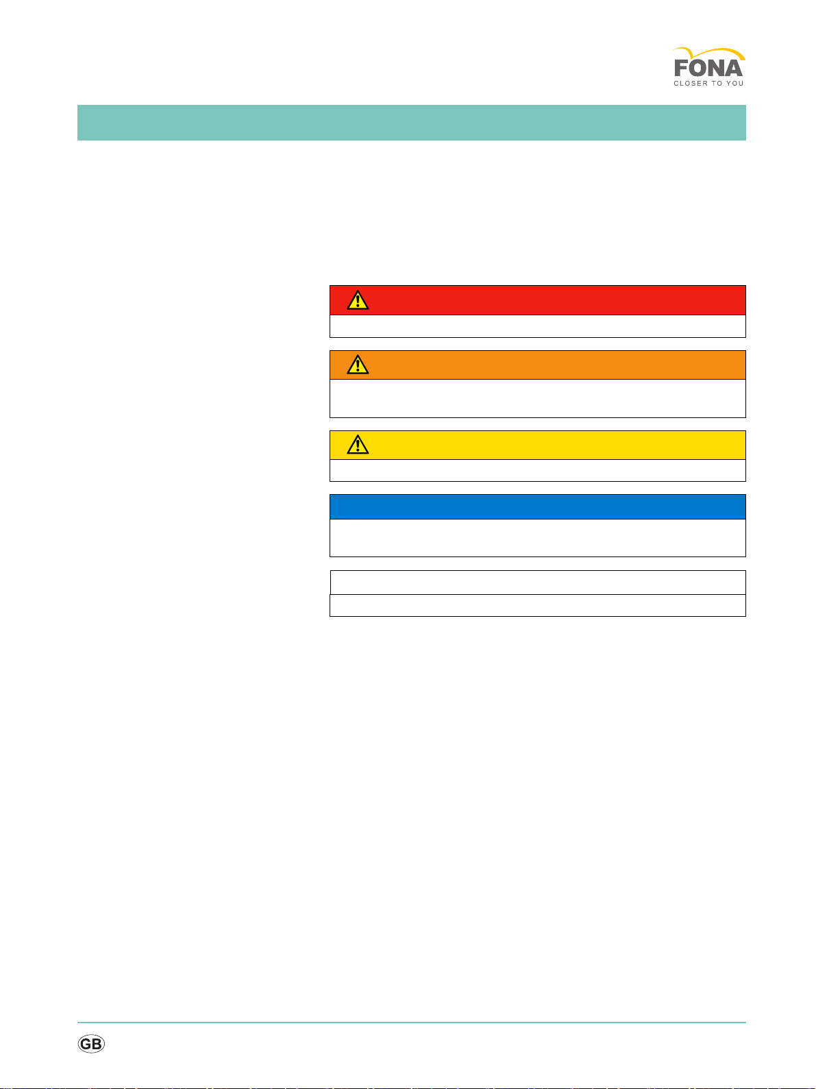
1.1.1 Identification of the danger levels
To prevent personal injury and material damage, please observe the
warning and safety information provided in these operating instructions.
Such information is highlighted as follows:
Tip: Information for simplifying work.
DANGER
An imminent danger that could result in serious bodily injury or death.
WARNING
A possibly dangerous situation that could result in serious bodily injury
or death.
CAUTION
A possibly dangerous situation that could result in slight bodily injury.
NOTICE
A possibly harmful situation which could lead to damage of the product
or an object in its environment.
IMPORTANT
Application instructions and other important information.
Service Manual
båÖäáëÜ
cê~å´~áë
5
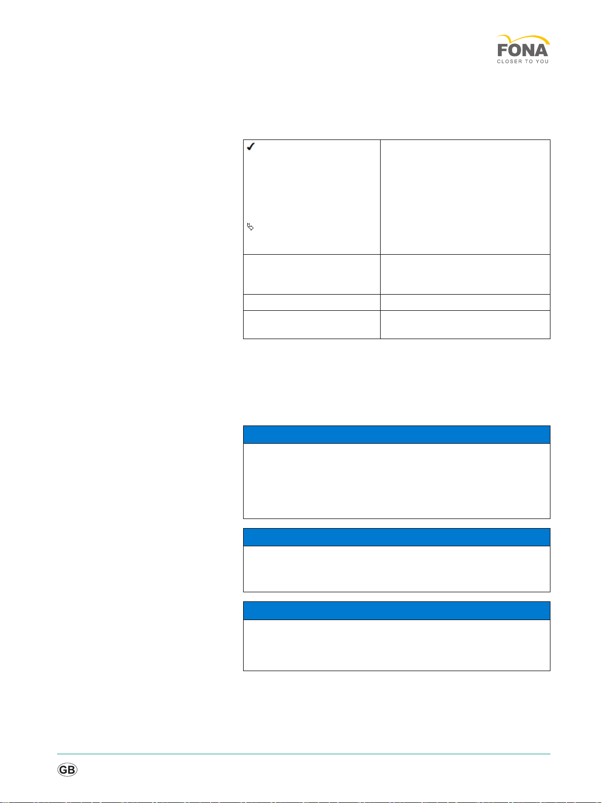
1.1.2 Formats and symbols used
The formats and symbols used in this document have the following
meaning:
1.2 Safety
1.2.1 Basic safety information
1.2.1.1 Prerequisites
1.2.1.2 Modifications to the product
Modifications to this product which might affect the safety of the system
owner, patients or other persons are prohibited by law!
Prerequisite
1. First action step
2. Second action step
or
➢ Alternative action
Result
➢Individual action step
Prompts you to do something.
See “Formats and symbols
used [ → 5]”
Identifies a reference to another text
passage and specifies its page
number.
● List Designates a list.
“Command / menu item” Indicates commands, menu items or
quotations.
NOTICE
Important information on building installation
In order to prevent the risk of an electric shock, this unit must only be
connected to a supply mains with a ground wire.
The building installation must be performed by a qualified expert in
compliance with the national regulations.
NOTICE
Restrictions regarding installation site
The system is not intended for operation in areas subject to explosion
hazards.
NOTICE
Do not damage the unit!
The unit can be damaged if opened improperly.
It is expressly prohibited to open the unit with tools!
6
MyCrown Design
1.2.1.3 Movement and stability of the unit
1.2.1.4 Maintenance and repair
As distributors of dental instruments and laboratory equipment, we can
assume responsibility for the safety properties of the unit only if the
following points are observed:
● The maintenance and repair of this unit may be performed only by
FONA Dental or by agencies authorized by FONA Dental.
● Components which have failed and influence the safety of the unit
must be replaced with original (OEM) spare parts.
Please request a certificate whenever you have such work performed. It
should include:
● The type and scope of work.
● Any changes made in the rated parameters or working range.
● Date, name of company and signature.
1.2.1.5 Accessories
In order to ensure product safety, this device may be operated only with
original FONA Dental accessories or third-party accessories expressly
approved by FONA Dental. In particular, only the power cable supplied
with the unit or the corresponding original spare part may be used with
the unit. The user is responsible for any damage resulting from the use of
non-approved accessories.
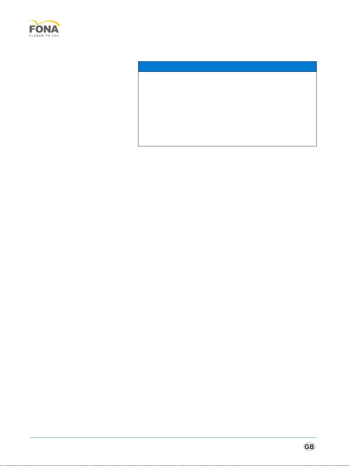
NOTICE
The unit can overturn or slip away
For reasons of tilt stability, the unit must be pulled by its side handles
when being moved. If you push the unit, obstacles on the floor could
block its wheels, thus causing it to overturn.
The wheels of the unit have brakes which can be locked to ensure
secure positioning. If the unit is steeply inclined or standing on a slippery
surface and lateral forces are acting on it, it may slide even though the
wheel brakes are locked.
➢Always make sure that the unit's footprint is a flat, nonskid surface.
Service Manual
båÖäáëÜ
cê~å´~áë
7
1.2.2 Safety labels
Plug connections of external interfaces
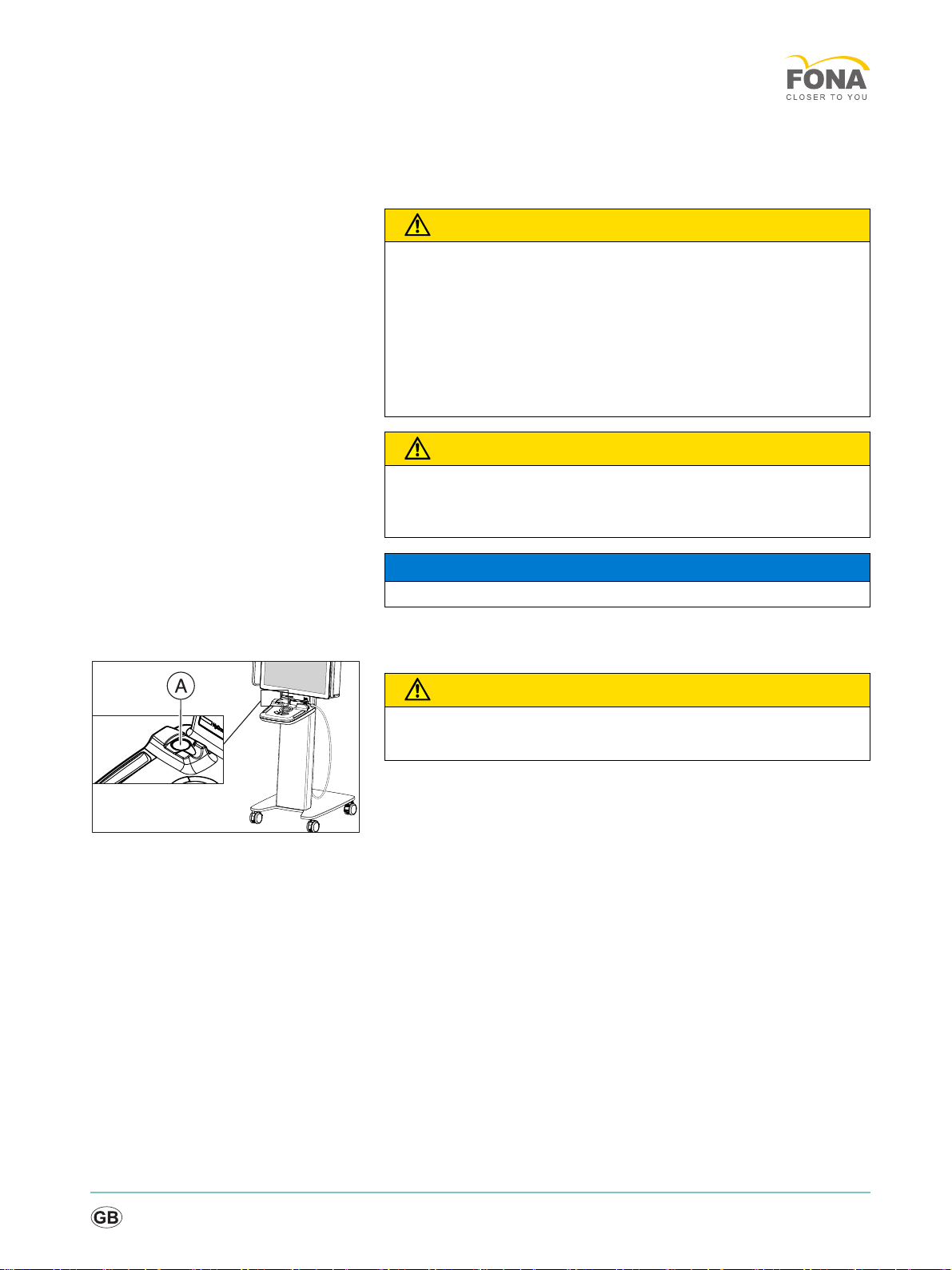
Heater plate
CAUTION
Additional devices connected to external interfaces must be tested
according to the relevant standards, e.g.:
EN 60601-1:1990 + A1:1993 + A2:1995 based on IEC 60601-1, EN
60950-1:2001 based on IEC 60950-1:2001, EN61010-1:2001 based on
IEC 61010-1:2001, UL 60601-1 Part 1: first edition 2003, UL 60950 third
edition 2000, UL 3101-1 Part 1 first edition 1993).
They must be installed outside of the patient area (a radius of 1.5m
surrounding the patient).
CAUTION
Low voltages are applied to the sockets for connecting external
interfaces.
➢Do not touch the pins of the connectors.
NOTICE
The externally connected cables must not be subjected to pulling stress.
CAUTION
Risk of burns due to hot surface!
➢Never touch the heater plate (A)!
8
MyCrown Design
1.2.3 Electrostatic charge
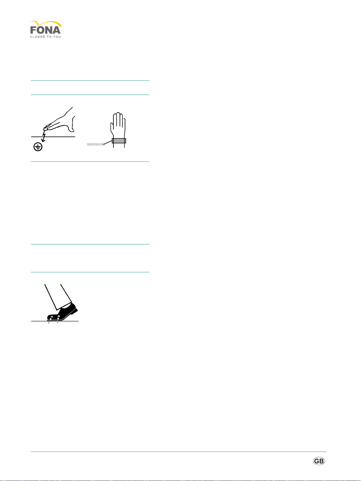
1.2.3.1 ESD protective measures
ESD ESD stands for ElectroStatic Discharge.
ESD protective measures ESD protective measures include:
● Procedures for preventing electrostatic charge build-up (e.g. air
conditioning, air moistening, conductive floor coverings and non-
synthetic clothing)
● Discharging the electrostatic charges of your own body on the frame
of the UNIT, the protective ground wire or large metallic objects
● Connecting yourself to ground using a wrist band.
Training We therefore recommend that all persons working with this system be
instructed on the significance of this warning label. Furthermore, they also
should receive training in the physics of electrostatic discharges which
can occur in the practice and the destruction of electronic components
which may result if such components are touched by electrostatically
charged USERS.
The content of this training is explained in the Chapter "About the physics
of electrostatic charges" [ → 8].
1.2.3.2 About the physics of electrostatic charges
What is an electrostatic charge? An electrostatic charge is a voltage field on and in an object (e.g. a human
body) which is protected against conductance to ground potential by a
nonconductive layer (e.g. a shoe sole).
Formation of an electrostatic charge
Electrostatic charges generally build up whenever two bodies are rubbed
against each other, e.g. when walking (shoe soles against the floor) or
driving a vehicle (tires against the street pavement).
Service Manual
båÖäáëÜ
cê~å´~áë
9
Amount of charge The amount of charge depends on several factors:
Thus the charge is higher in an environment with low air humidity than in
one with high air humidity; it is also higher with synthetic materials than
with natural materials (clothing, floor coverings).
Electrostatic discharge must be preceded by electrostatic charging.
The following rule of thumb can be applied to assess the transient
voltages resulting from an electrostatic discharge.
An electrostatic discharge is:
● perceptible at 3,000 V or higher
● audible at 5,000 V or higher (cracking, crackling)
● visible at 10,000 V or higher (arc-over)
The transient currents resulting from these discharges have a magnitude
of 10 amperes. They are not hazardous for humans because they last for
only several nanoseconds.
Background Integrated circuits (logical circuits and microprocessors) are used to
implement a wide variety of functions in dental/X-ray/CAD/CAM systems.
The circuits must be miniaturized to a very high degree in order to include
as many functions as possible on these chips. This leads to structure
thicknesses as low as a few ten thousandths of a millimeter.
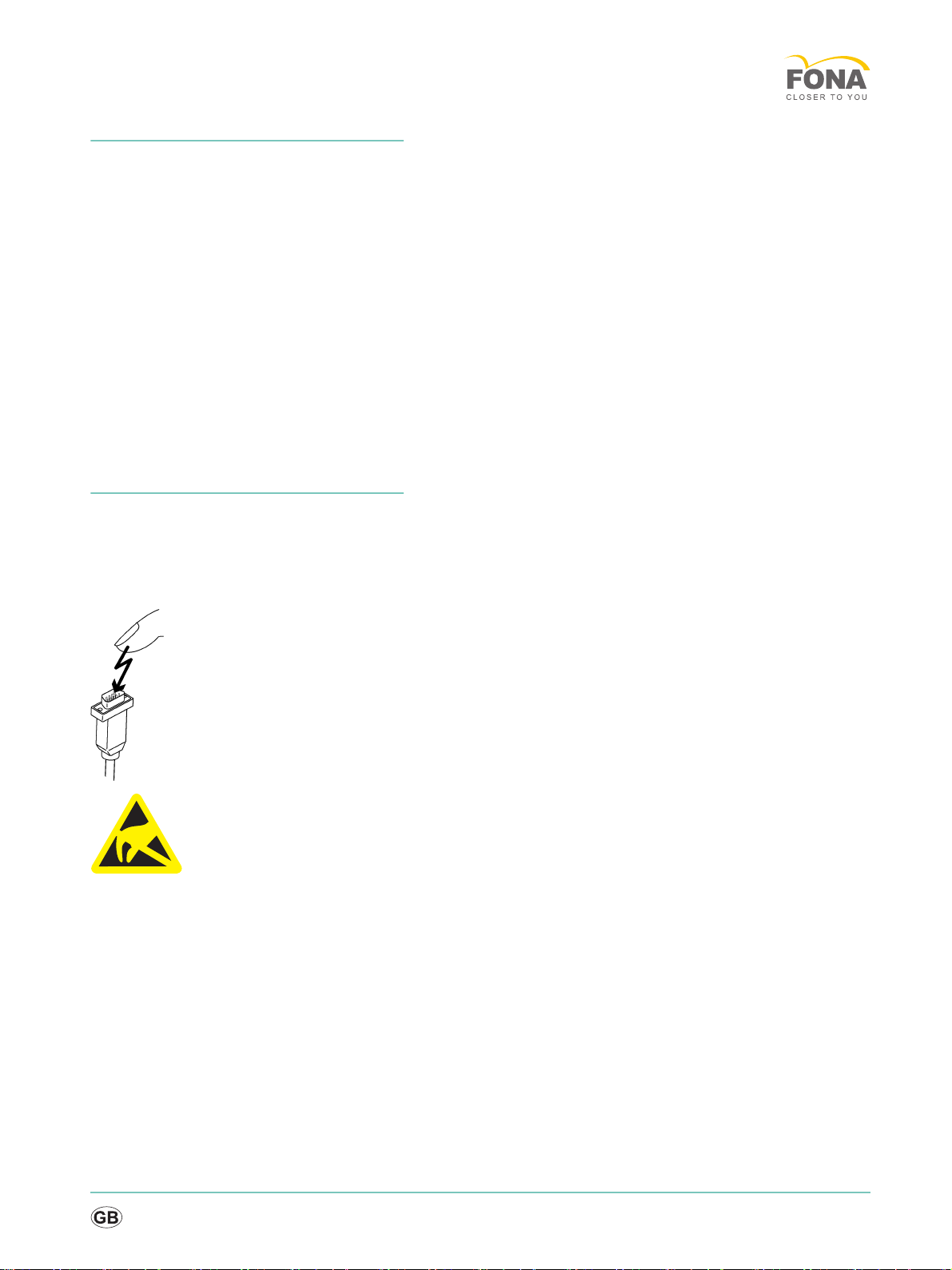
It is obvious that integrated circuits which are connected to plugs leading
outside of the unit via cables are sensitive to electrostatic discharge.
Even voltages which are imperceptible to the user can cause breakdown
of the structures, thus leading to a discharge current which melts the chip
in the affected areas. Damage to individual integrated circuits may cause
malfunction or failure of the system.
To prevent this from happening, the ESD warning label next to the plug
warns of this hazard. ESD stands for ElectroStatic Discharge.
Connector pins or sockets bearing ESD warning labels must not be
touched or interconnected without ESD protective measures.
1.2.4 Radio interference
MyCrown Design is Wi-Fi-compatible. It is designed for transmissions
(sending and receiving) in various frequency ranges from 2412.0 MHz to
5825.0 MHz
By intercepting the transmissions, the wireless network module (WLAN/
Wi-Fi) determines which system frequencies are available and then
operates in the available ranges.
The wireless network module transmits at a maximum power of 0.12 W.
The system can cause radio interference or interrupt the operation of
units in the vicinity.
If necessary, take measures to remedy this, for example realign or move
the MyCrown Design acquisition unit or shield the location.
10
MyCrown Design
1.3 General information
Nominal line voltage ranges MyCrown Design works in the following ranges:
Wireless phone interference with
medical electrical equipment
Replacing parts
Switch the device off and disconnect the power plug before replacing
parts.
The item numbers for ordering spare parts can be found in the spare parts
list.
The diagrams contained in the spare parts list provide a useful guide
when replacing parts.
Before replacing the boards, observe the ESD protective measures.
Disposal Observe the information on disposal in the relevant operating
instructions.
Installation site Observe the information on the installation site in the relevant operating
instructions.
Rated line voltage 100 - 250 VAC /50 - 60 Hz
Nominal current 3.0A to 2.0A
NOTICE
To ensure safe operation of medical electrical equipment, the use of
mobile wireless phones in practice or hospital environments is
prohibited.
WARNING
Potentially lethal shock hazard when working near the power supply unit
Disconnect from the line power supply.
Check for zero potential.

Service Manual
båÖäáëÜ
cê~å´~áë
11
1.4 Additional information
In addition, you also require:
● FONA spare parts catalog in the OEM shop
● Wiring diagrams MyCrown Design
● Operating Instructions MyCrown Design
Tools
● Torx screwdriver, size 6; 10; 20; 30; 40, shank length at least 70 mm
● Phillips screwdriver for M3
● Blade screwdriver (for heater fuse)
● Open-end/socket wrench, 12mm A/F
● Open-end wrench SW 18 (for ring nuts on the camera)
● Open-end wrench SW 8 (for Wi-Fi antenna cables)
Auxiliary tools & equipment
● USB keyboard
● USB mouse
12
Service Manual
båÖäáëÜ
cê~å´~áë
2 Installation
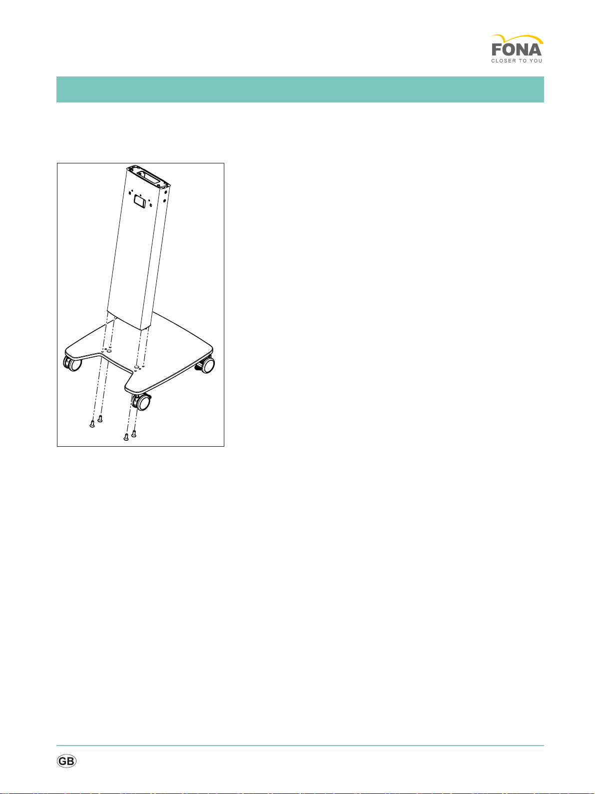
2.1 Preparing the cart
Mounting the columns to the cart
➢Screw the columns on to the cart with 4 screws.
Service Manual
båÖäáëÜ
cê~å´~áë
13
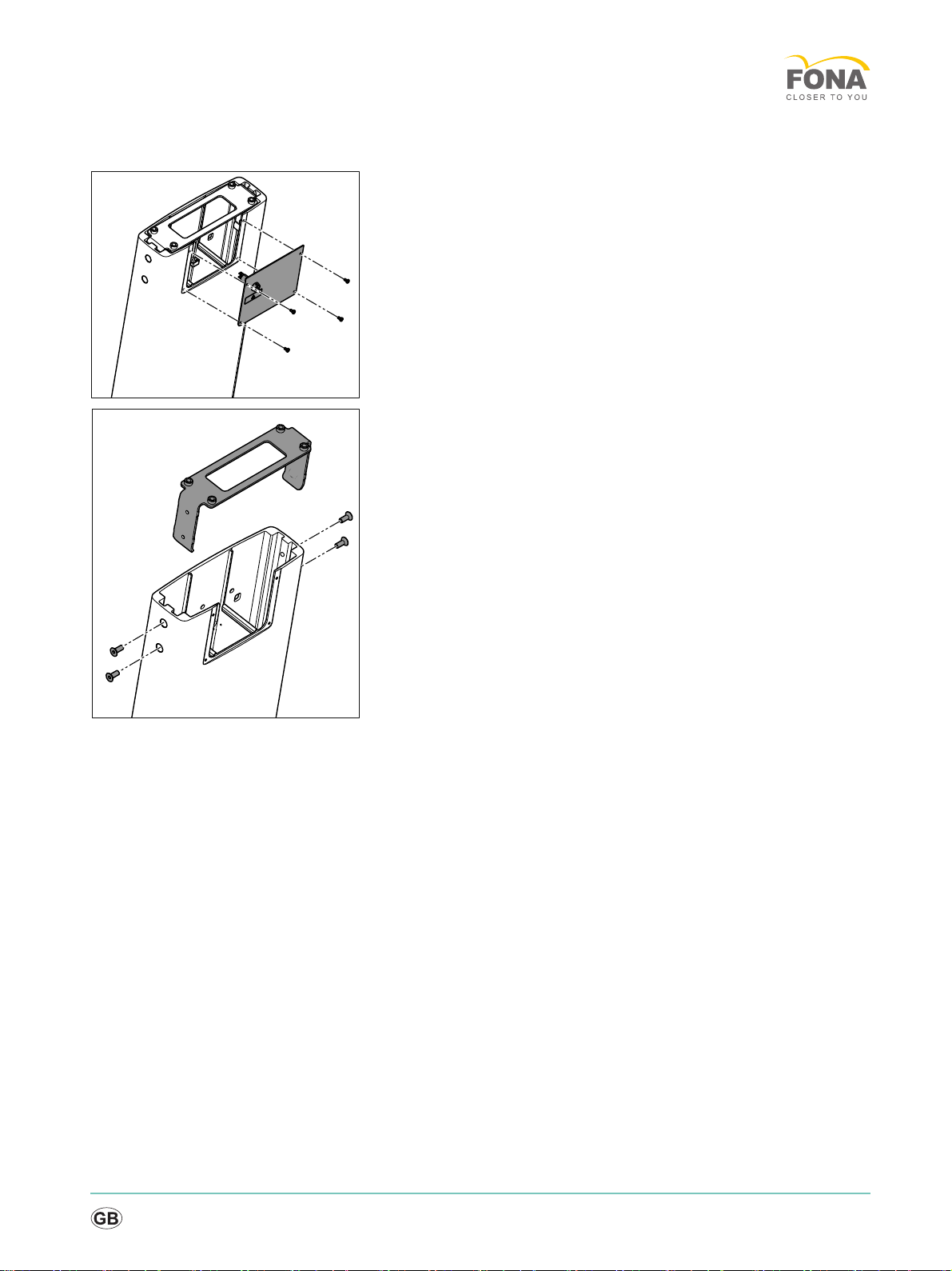
Removing the cover and carrier plate
1. Remove the top cover from the column.
2. Remove the carrier plate for the controller from the column.

14
MyCrown Design
2.2 Preparing the controller
1. Mount the carrier plate on the controller with 4 screws.
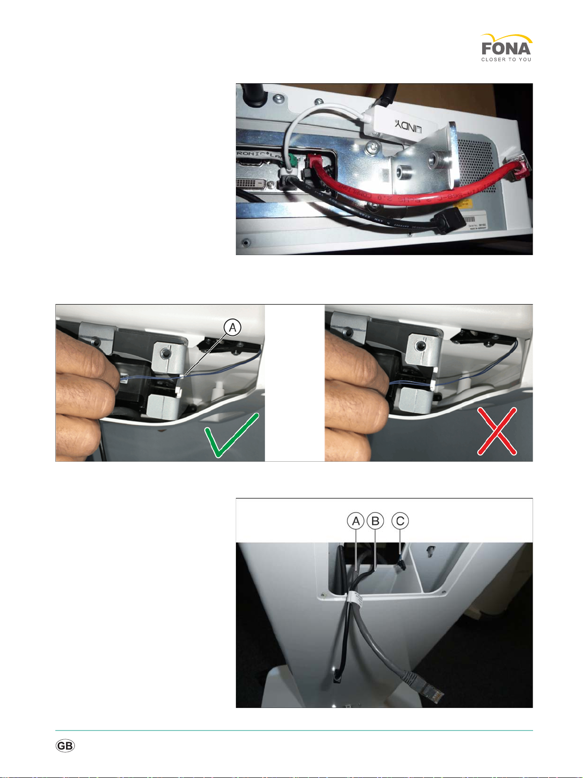
2. Connect the following cables provided to the controller:
● USB to LAN converter to USB interface (A).
● USB extension to USB interface (B)
● LAN extension to LAN socket (C).
Service Manual
båÖäáëÜ
cê~å´~áë
15
Controller with connected cables
2.3 Mounting the control panel
1. Route the heating cable as shown in the illustration.
NOTICE! Do not jam in the heating cable.
16
MyCrown Design
2. Route the following 3 cables through the feedthrough in the column:
LAN cable for radio module (A)
USB cable on the trackball unit (B)
heating cable (C)
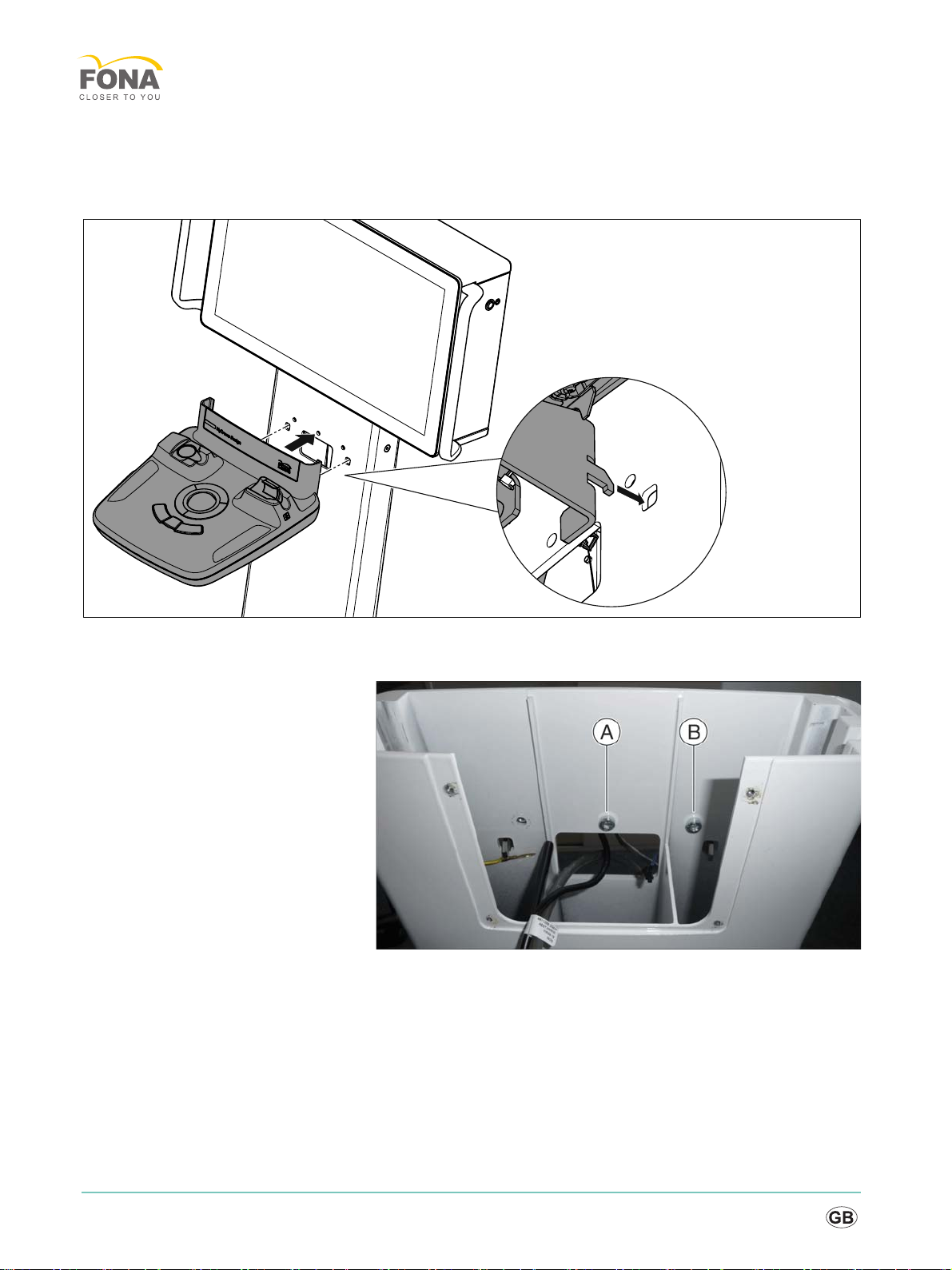
3. Hang the control panel on the column. Both hooks on the control
panel must be mounted in the recesses in the column.
4. Fasten the control panel with 2 screws at positions (A) and (B). The
protective ground wires will be screwed in later using the third screw.
Service Manual
båÖäáëÜ
cê~å´~áë
17
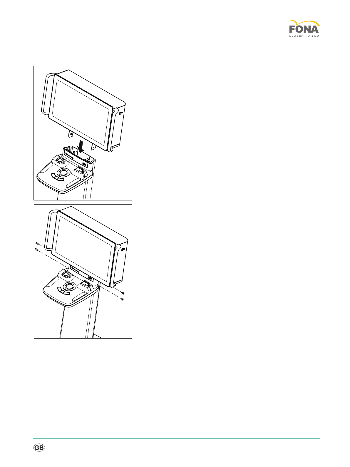
2.4 Installing the controller
1. Insert the controller into the column from above.
NOTICE! Weight approx. 14 kg.
NOTICE! Do not jam in the cable.
2. Fasten the controller securely with 4 countersunk screws. To do so,
the controller must be raised slightly.
18
MyCrown Design
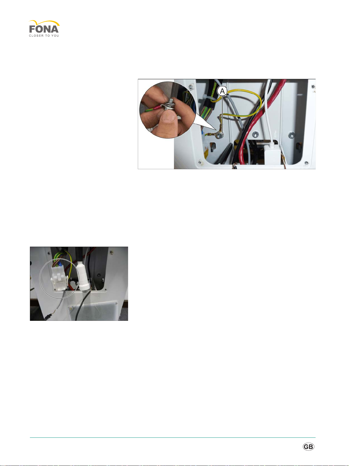
2.5 Connecting the cables
Fastening the protective ground wires
➢Fasten the 2 protective ground wires at position (A).
Please note the order:
screw > washer > protective ground wire > protective ground wire >
contact wheel
The claw fasteners of the contact wheel must be pointed towards the
sheet metal wall (upwards in the illustration).
NOTICE! Do not allow any small parts to fall into the column.
Connecting cables
➢Connect the following cables:
● Power cable
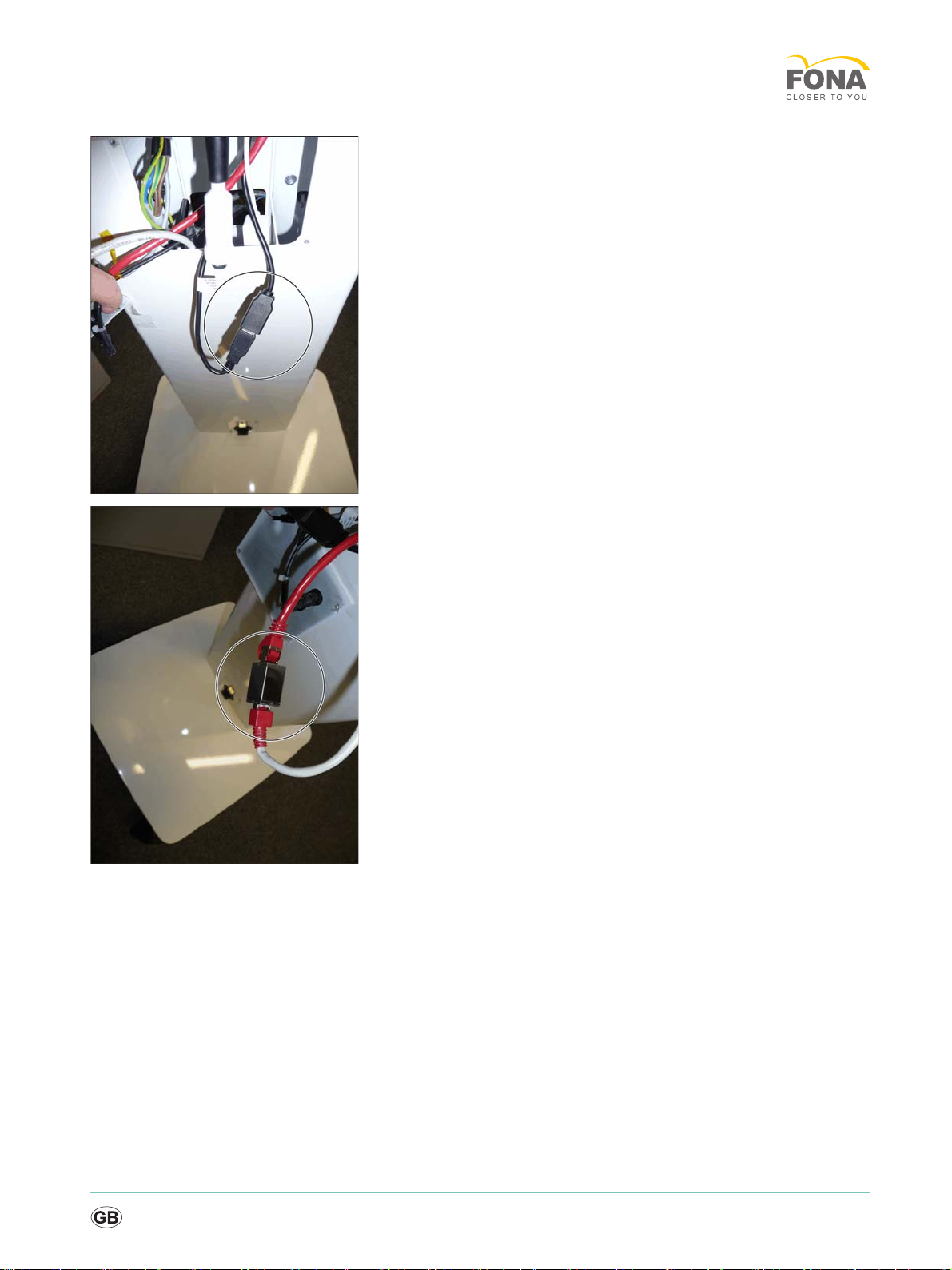
Service Manual
båÖäáëÜ
cê~å´~áë
19
● USB extension cable (from controller) and USB cable from control
panel
● LAN cable from column and LAN extension cable from the controller
20
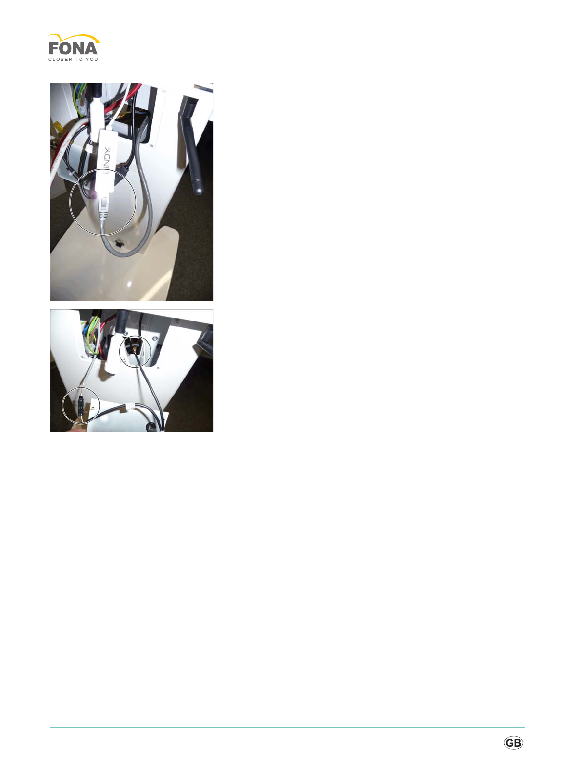
MyCrown Design
● LAN cable from the control panel and USB-to-LAN converter
● Fuse on the cover with both heating cables (from control unit und
controller)
➢Route all cables in the column.
Table of contents
Other Fona Medical Equipment manuals


