1. Introduction 4
1.1 Technical data summary 4
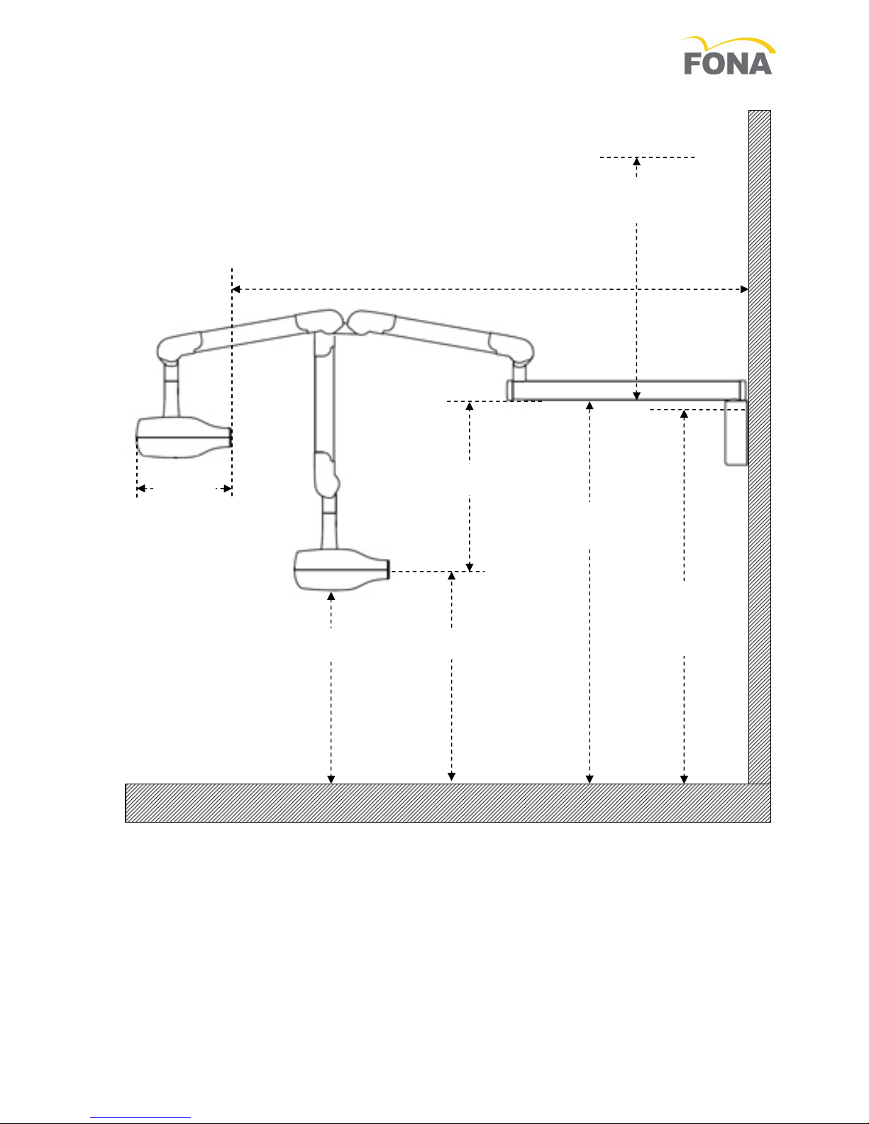
1.2 Dimensions of wall systems
2. System configurations 6
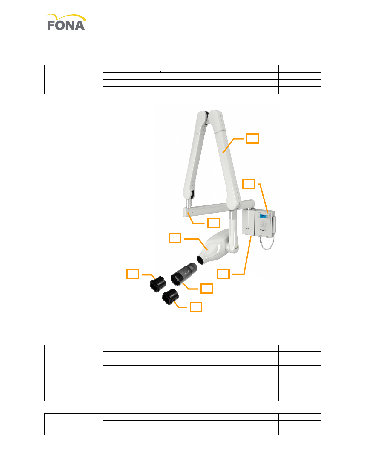
2.1 Wall mounted systems 6
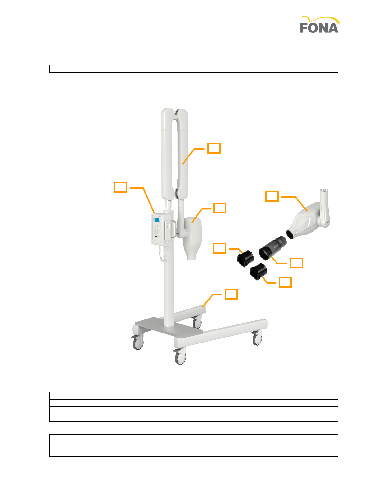
2.2 Mobile system 7
2.3 Accessories 8
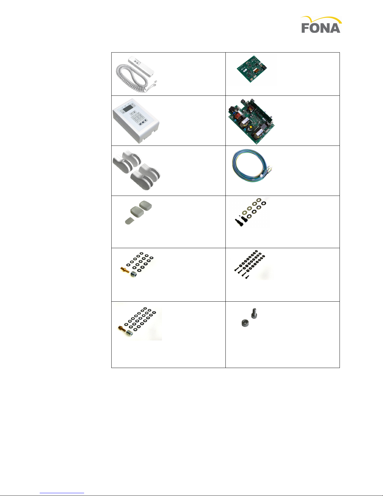
2.4 Spare parts 9
2. Layout of power driver unit 10
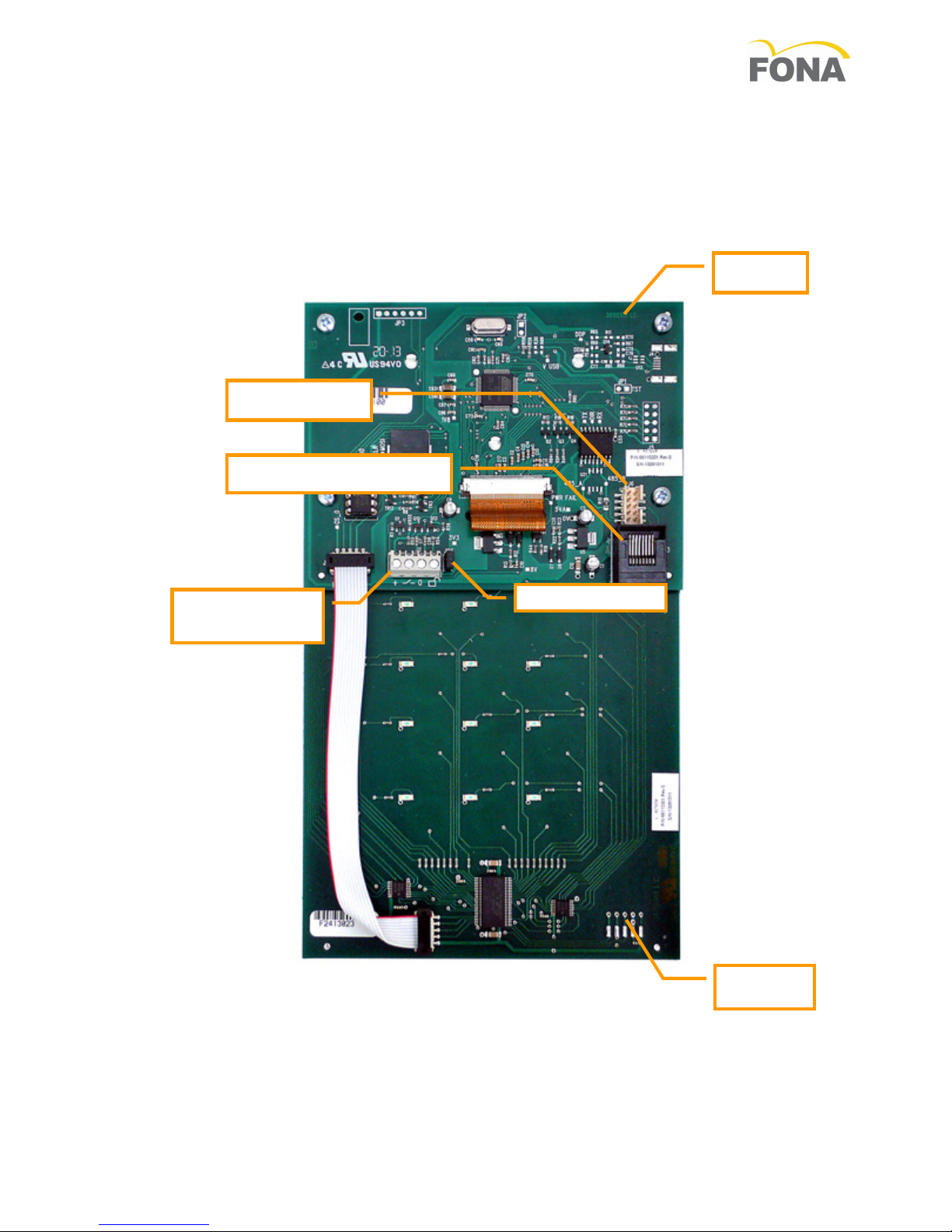
2.6 Layout of control unit board 11
3. Assembly and Installation 12
3.1 Possibilities of installation 12
3.1.1 Unit in the treatment room with local hand
switch 12
3.1.2 Unit in the treatment room with hand
switch remote 12
3.1.3 X-ray emission in the treatment room with
remote control and release switch 12
3.2 Structural Requirements 13
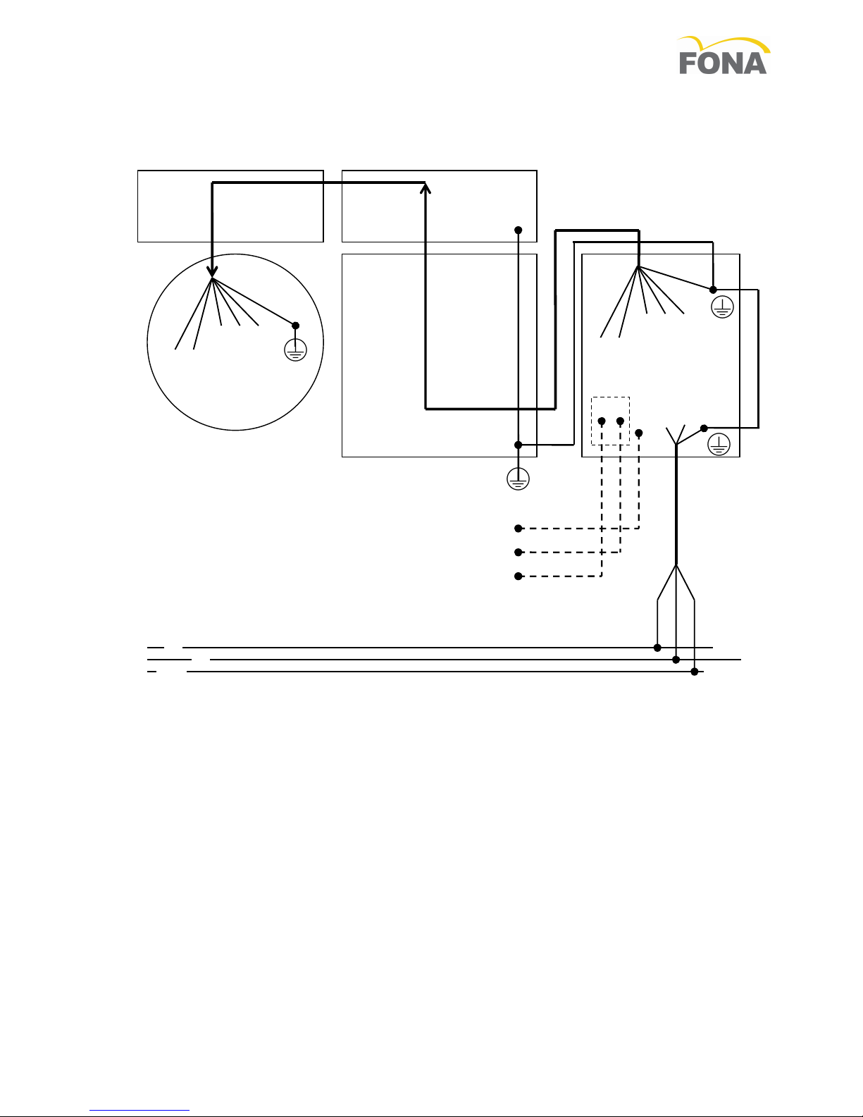
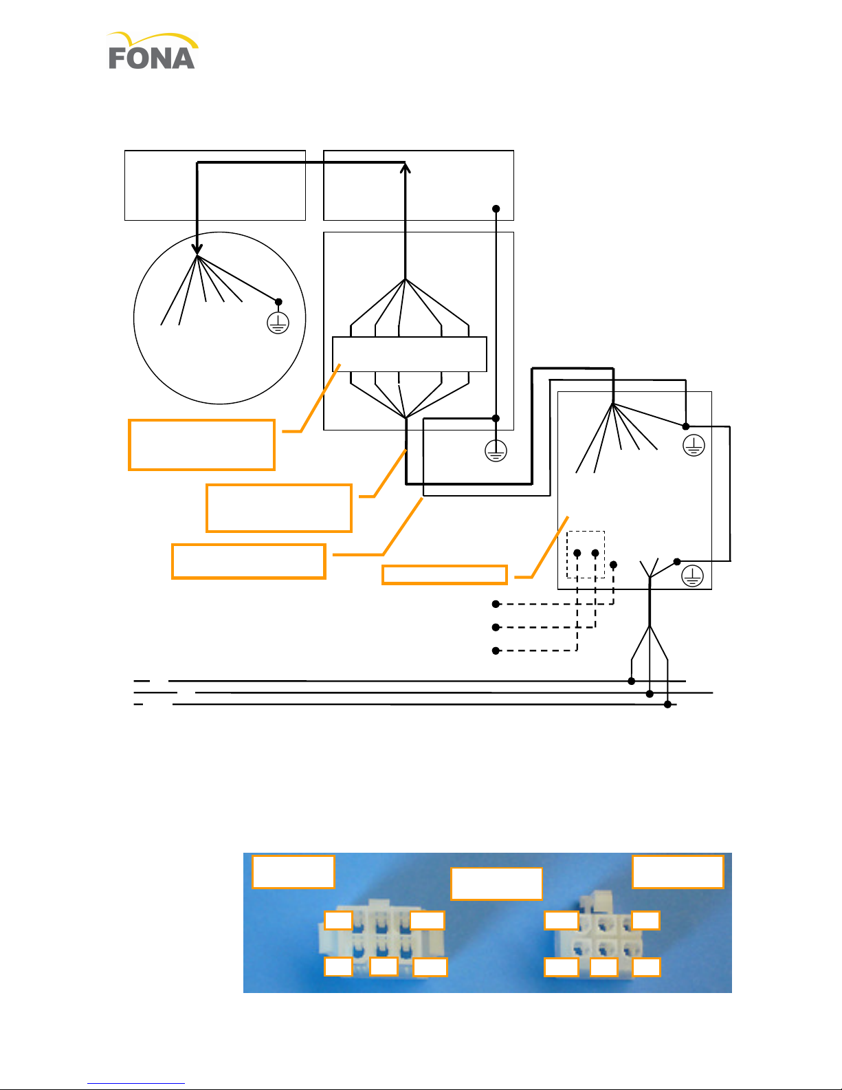
3.3 Electrical connections 14
3.3.1 Common bolt for earth connection and
bonding 14
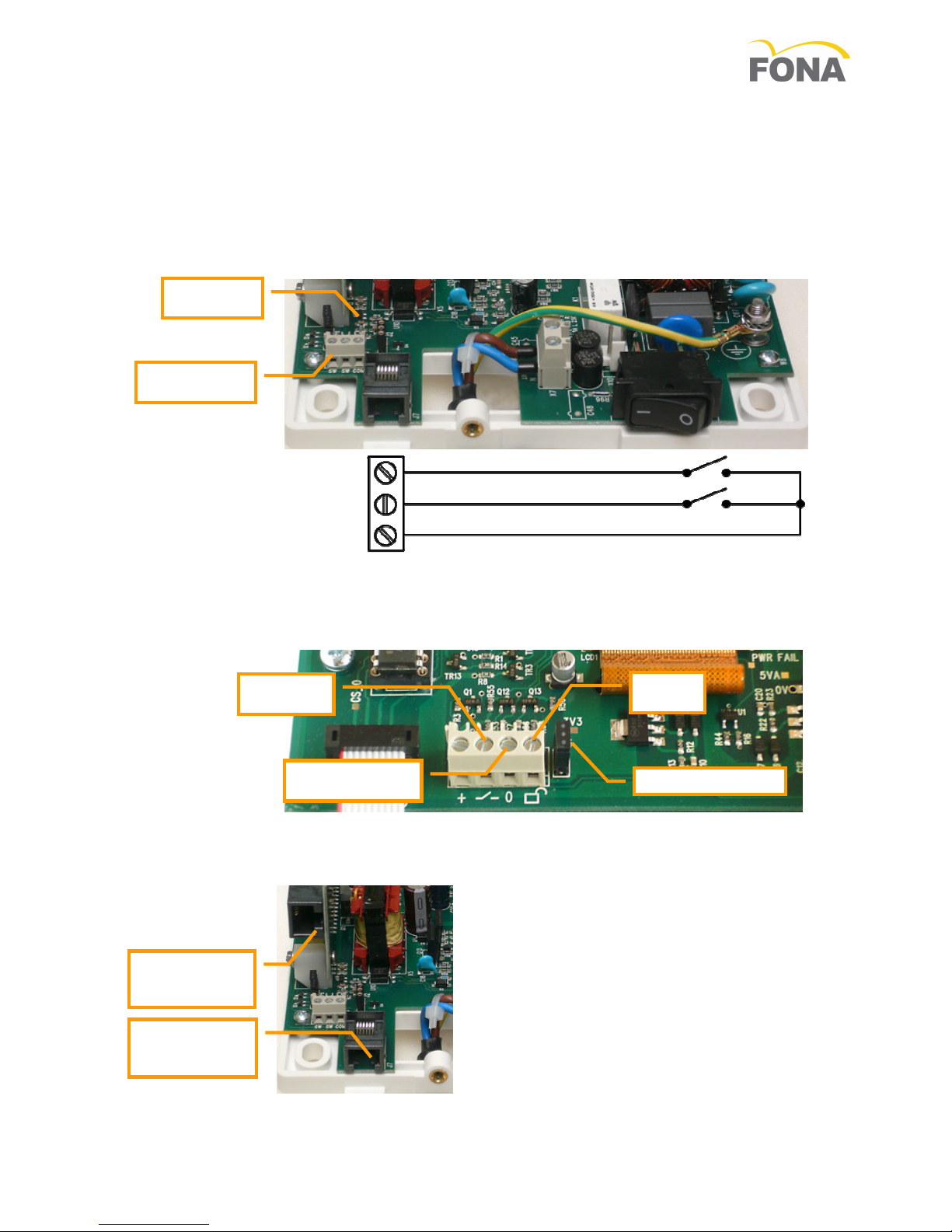
3.3.2 Wiring for local or remote hand-switch
connection 14
3.3.3 Wiring the unit with local control 1
3.3.4 Wiring the unit with remote control 16
3.3. Reduction in length of cable for filament
and high voltage supply 16
3.4 Optional Items 17
3.4.1 Optional door contact and second enable
17
3.4.2 Optional remote hand-switch and key lock
17
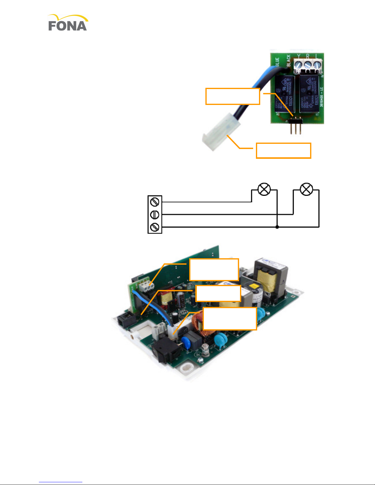
3.4.3 Optional board for external lights 18
3. Installation of wall system 19
3. .1 Mounting the wall adaptor 19
3. .2 Mounting the PDCU 20
3. .3 Mounting the Support Arm 20
3. .4 Mounting the Scissor Arm 21
3. . Mounting and Connecting the X-ray Head
22
3. .6 Mounting the Beam Limiting Device 22
3. .7 Connecting the PDCU to the mains line 23
3. .8 Connecting the PDCU to the tube-head
with WA at side 24
3. .9 Connecting tube-head and PDCU remote 2
3. .10 Connecting the Hand-Switch 26
3. .11 Optional Remote Hand-Switch 26
3. .12 Final set-up 26
3.6 Installation of mobile system 27
3.6.1 Assembling the Mobile Stand 27
3.6.2 Mounting the scissor arm 27
3.6.3 Mounting the PDCU 27
3.6.4 Preparing the line voltage cable and the
earth provision 27
3.6. Connecting the PDCU 28
3.6.6 Activation of Fuse 2 28
3.6.7 Mounting and Connecting the X-ray Head
28
3.6.8 Mounting the Beam Limiting Device 28
3.6.9 Final Set-Up 28
4. Service 29
4.1 Line fuses 29
4.2 Control panel 29
4.3 Service data 29
4.4 Loading of the software 29
4. XDC test JIG 30
4.6 Replacement of tube-head XDC 31
4.7 Replacement of PDCU 33
4.8 Replacement of mains cable 34
. Maintenance 3
.1 Checking labels 3
.2 Maintenance of wall adaptor 36
.3 Maintenance of support arm 36
.4 Maintenance of scissor arm 36
. Maintenance of X-ray Head 38
.6 Maintenance of the mobile stand 38
.7 Maintenance of the control unit 39
.8 Mechanical checks 40
.9 Electrical Checks 40
.10 Tube current verification 41
.11 Exposure Time and kV verification 42
.12 Radiation dose assessment 43
6. Reporting 44
6.1 Installation report 44
6.2 Periodic inspection and preventive
maintenance report 4