FOR-A UFH-70ADA User manual

UFH-70ADA
Audio Distribution Amplifier
1st Edition
OPERATION
MANUAL


Precautions[MA1]
Important Safety Warnings
[Power]
Do not place or drop heavy or sharp-edged objects on power cord. A damaged cord
can cause fire or electrical shock hazards. Regularly check power cord for
excessive wear or damage to avoid possible fire / electrical hazards.
[Circuitry Access]
Do not touch any parts / circuitry with a high heat factor.
Capacitors can retain enough electric charge to cause mild to serious shock, even
after power is disconnected. Capacitors associated with the power supply are
especially hazardous. Avoid contact with any capacitors.
Unit should not be operated or stored with cover, panels, and / or casing removed.
Operating unit with circuitry exposed could result in electric shock / fire hazards or
unit malfunction.
[Potential Hazards]
If abnormal smells or noises are noticed coming from the unit, turn power off
immediately and disconnect power cord to avoid potentially hazardous conditions. If
problems similar to above occur, contact authorized service representative before
attempting to again operate unit.
[Consumables]
The consumables used in unit must be replaced periodically. For further details on
which parts are consumables and when they should be replaced, refer to the
specifications at the end of the Operation Manual. Since the service life of the
consumables varies greatly depending on the environment in which they are used,
they should be replaced at an early date. For details on replacing the consumables,
contact your dealer.
Caution
Stop
Hazard
Stop
Caution

Upon Receipt
Unpacking
UFH-70ADA units and their accessories are fully inspected and adjusted prior to shipment.
Operation can be performed immediately upon completing all required connections and
operational settings.
Check your received items against the packing lists below.
ITEM QTY REMARKS
UFH-70ADA 1 1 front module
1 rear module
Operation Manual 1
Check
Check to ensure no damage has occurred during shipment. If damage has occurred, or items
are missing, inform your supplier immediately.

Table of Contents
1. Prior to Starting...........................................................................................................................1
1-1. Welcome.............................................................................................................................1
1-2. About the UFH-70ADA........................................................................................................1
1-3. About This Manual..............................................................................................................1
2. Panel Descriptions......................................................................................................................2
2-1. Front Panel.........................................................................................................................2
2-2. Rear Panel..........................................................................................................................2
3. Connection..................................................................................................................................3
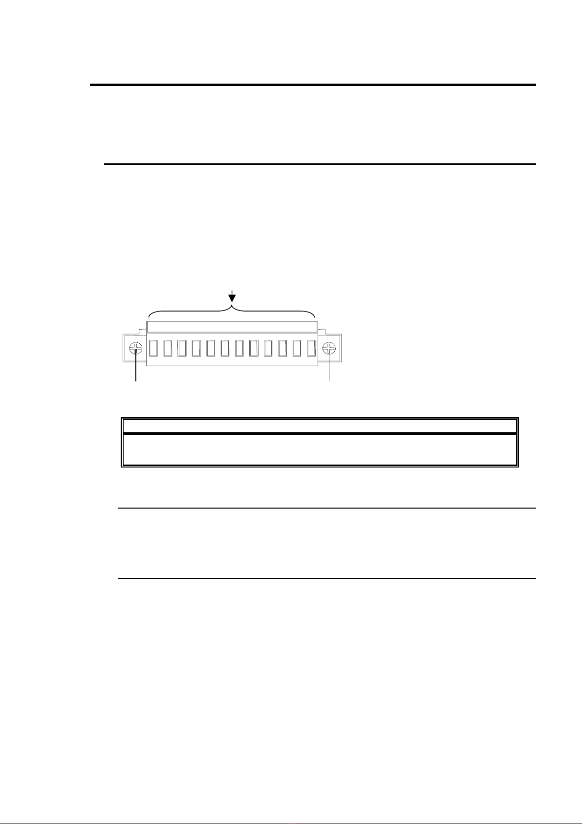
3-1. Connecting Wiring to Terminal Block ..................................................................................3
3-1-1. Balanced Input/Output................................................................................................3
3-1-2. Unbalanced Input/Output............................................................................................3
3-2. Connection Example...........................................................................................................4
4. Internal Block Diagram................................................................................................................6
5. Internal Settings..........................................................................................................................7
5-1. Operation Mode (SW4).......................................................................................................7
5-2. Input Termination Impedance (SW1, SW2).........................................................................8
5-3. GAIN Setting (SW3, SW5) .................................................................................................9
6. Specifications and Dimensions .................................................................................................10
6-1. Specifications....................................................................................................................10
6-2. Dimensions.......................................................................................................................11


1
1. Prior to Starting
1-1. Welcome
Congratulations! By purchasing UFH-70ADA AUDIO DISTRIBUTION AMPLIFIER you have
entered the world of FOR-A and its many innovative products. Thank you for your patronage and
we hope you will turn to FOR-A products again and again to satisfy your video and audio needs.
FOR-A provides a wide range of products, from basic support units to complex system
controllers, which have been increasingly joined by products for computer video based systems.
Whatever your needs, talk to your FOR-A representative. We will do our best to be of continuing
service to you.
1-2. About the UFH-70ADA
Features
Mountable to FOR-A UFH system frames
Gain control available on the front panel
Presettable output level control.
Single channel mode (one-input / seven-output) and Dual channel mode (two systems of
one-input / three-output) selectable
1-3. About This Manual
This manual is intended to help the user easily operate the UFH-70ADA and make full use of its
functions during operations. Before connecting or operating your unit, read this operation
manual thoroughly to ensure you understand the product. After reading, it is important to keep
this manual in a safe place and available for reference.

2
2. Panel Descriptions
2-1. Front Panel
(1) Power indicator The power indicator is lit whenever the supply curcuit on the
board is operating properly.
(2) GAIN A Used to control audio gain in the range from -6dB to +6dB.
(3) GAIN B (*1) Used to control audio gain in the range from -6dB to +6dB.
(4) INTERFACE Not used.
(*1) Available in dual channel mode (two systems of one-input / three-output).
2-2. Rear Panel
If Single Channel mode:
AUDIO IN Used to input audio signals.
(1) OUT1
OUT2
OUT3 Used to output audio signals.
(2)
OUT4
OUT5
OUT6
OUT7 Used to output audio signals.
If Dual Channel mode:
IN A Used to input audio signals for system A.
(1) OUT A1
OUT A2
OUT A3 Used to output audio signals for system A.
IN B Used to input audio signals for system B.
(2) OUT B1
OUT B2
OUT B3 Used to output audio signals for system B.
UFH-70ADA
INTERFACE
(OPTION)
GAIN A GAIN B-15V+15V
UFH-70ADA
+3.3V
(1) (2) (3) (4)
OUT A1IN A IN B OUT B1OUT A2 OUT A3 OUT B2 OUT B3
+- -++- -++--++- -+
ANALOG AUDIO IN OUT1 OUT2 OUT3 OUT4 OUT5 OUT6 OUT7
UFH-70ADA
GGGG GGGG
(1) (2)

3
3. Connection
Refer to figure below for connecting the UFH-70ADA to other devices.
Note that before installing the UFH-70ADA into a system frame, you should thoroughly read the
operation manual for the System Frame where you will be installing.
3-1. Connecting Wiring to Terminal Block
To connect audio wiring to the terminal block on the UFH-70ADA rear module, follow the steps
below.
1) Unscrew the cover screws at both sides of the terminal block using a small Phillips-head
screw driver.
2) Remove the terminal block cover forward. Set it aside.
3) Release the port screw on the top of the terminal block by using the same screw driver.
4) Insert the wire end into the port and secure the cable to the port with the port screw.
IMPORTANT
Use AWG16 to 28 wire. Strip the wire shielding so that approximately 5mm of each
wire is exposed.
3-1-1. Balanced Input/Output
For balanced input and output, connect the hot, cold, and shield of the audio signal to their
respective terminals (+, - and G for each).
3-1-2. Unbalanced Input/Output
For unbalanced input and output, connect the analog audio signal line to hot and shield
(ground) line to both cold and shield. After the connection has been made, check the level
and adjust it as required by using the GAIN dial.
(1) (1)
+-
GG
-
++-
G-
+G
(2) Top of the terminal block

4
3-2. Connection Example
(1) Single channel mode (one input to seven outputs)
(2) Dual channel mode (Two systems of one input to three outputs)
Audio Signal
AUDIO IN OUT 1
OUT 2
OUT 3
OUT 4
UFH-70ADA
System frame
OUT 5
OUT 6
OUT 7
Audio
Signal
Audio signal
(System A)IN A OUT A1
OUT A2
OUT A3
UFH-70ADA
System frame
OUT B1
OUT B2
OUT B3
Audio signal
(System A)
IN B Audio signal
(System B)
Audio signal
(System B)

5
3-3. Starting Up UFH-70ADA
1) Release the screws at the both sides of the system frame front panel.
2) Power on the system frame to start up UFH-70ADA.
SYSTEM FRAM E
GENLOCK
12FAN
ALARM
TEMP DC POW UFH-112
POWER
1
2
POWER GENLOCK
12FAN
ALARM
TEMP DC POW

6
4. Internal Block Diagram
The internal block diagram of UFH-70ADA is as shown in the figure below.
OUT 1, OUT A1
OUT 2, OUT A2
OUT 3, OUT A3
OUT 4, IN B
OUT 5, OUT B1
OUT 6, OUT B2
OUT 7, OUT B3
・GAIN ADJUSTMENT
・GAIN SETTING
・GAIN ADJUSTMENT
・GAIN SETTING
AUDIO IN, IN A

7
5. Internal Settings
The following settings can be made via the front module of the UFH-70ADA.
Switch settings must be made prior to installing to the system frame.
5-1. Switch Location
5-2. Operation Mode (S301, S302 and S303)
These switches are used to select between single channel mode (one way) and dual channel
mode.
Switch Setting
S301 S302 S303 Operation Mode
A A A Single channel mode
A/B A/B A/B Dual channel mode
Factory default setting is single channel mode (all switches are at A position).
When changing the operation mode, be sure to set all of these switches at the same position.
Otherwise a malfunction may occur.
S303S302
S101 S201 S202S102
S301
S303
A/B
A
MODE SEL 3/3
S302
A/B
A
MODE SEL 2/3
S301
A/B
A
MODE SEL 1/3

8
5-3. Input Termination Impedance (S101 and S201)
S101 and S102 switches are used to select the impedance for AUDIO IN / IN A and IN B.
Switch Setting
S101 S201 Input Termination Impedance
HI HI High impedance
600Ω600Ω600Ω
Factory default setting is 600Ωtermination (S101 : 600Ω, S201 : 600Ω).
IN B ( + )
IN B ( - )
600Ω
S201
AUDIO IN, IN A ( + )
AUDIO IN, IN A ( - )
600Ω
S101
S101
HI
600Ω
600Ω/ HI
A
UDIO IN / IN A
S201
HI
600Ω
600Ω/ HI IN B
(Valid only for dual channel mode.)

9
5-4. GAIN Setting (S102 and S202)
S102 and S202 dipswitches are used to set input signal gain.
Pin number
1 2 3 4 Input Signal Gain
ON OFF ON OFF +8dB
ON ON OFF OFF +4dB
OFF OFF OFF OFF 0dB
OFF ON OFF OFF -4dB
OFF OFF ON OFF -8dB
Factory default setting is 0dB (all OFF).
1 2 3 4
OFF
S102
A
UDIO IN / IN A
1 2 3 4
OFF
S202
IN B
(Valid only for dual channel mode.)

10
6. Specifications and Dimensions
6-1. Specifications
* 0dB = 0.775V (rms)
Audio input Analog audio +4dB balanced
1 input (Single channel mode) or 2 inputs (Dual channel mode)
Input impedance 600Ω/High selectable
Audio output - Analog audio +4dB balanced at 600Ωimpedance
Seven outputs (Single channel mode)
- Analog audio +4dB balanced at 600Ωimpedance
Two systems of three outputs (Dual channel mode)
Output impedance Less than 100Ω
Minimum load
impedance 600Ω
Max. input/output
level +24dB at 600Ωimpedance
Frequency response 20Hz - 20kHz within ±0.2dB (based on 1kHz)
Gain -8dB/-4dB/0dB/+4dB/+8dB selectable
Gain range Input signal gain control in the range from -6.0dB to +6.0dB.
Distortion ratio Less than 0.02% (with 1kHz + 24dB input)
S/N ratio Better than 104dB (+24dB input with A- weight FILTER)
Temperature 10°C – 40°C
Humidity 30% – 90% (no condensation)
Power + 24VDC (supplied with System Frame)
Power Consumption Approx. 13.2VA (13.2W)
Weight Approx. 1.0 kg
Dimensions Front module: 138.5 (W) x 400 (D) mm
Rear module: 141 (W) x 101 (D) mm
Required slot 1 slot
Consumables None

11
6-2. Dimensions
(All dimensions in mm.)
OUT2ANALOG AUDIO IN OUT1 OUT3
OUT A1IN A IN B OU TB1OUT A2 OUT A3 OUT B2 O UTB 3
UFH-70ADA
INTERFACE
(O P TI ON )
GAIN A GAIN B-15V+15V+3.3V
87.8
(101)
379.5
(400)
20
141
+-GG
-
++-G-
+G+--
++--
+
UFH-70ADA
GGGG
OUT4 OUT5 OUT6 OUT7
CPU CARD (Option)
UFH-70ADA


Warning
This equipment has been tested and found to comply with the limits for a
Class A digital device, pursuant to Part 15 of FCC Rules. These limits are
designed to provide reasonable protection against harmful interference
when the equipment is operated in a commercial environment. This
equipment generates, uses, and can radiate radio frequency energy and,
if not installed and used in accordance with the instruction manual, may
cause harmful interference to radio communications. Operation of this
equipment in a residential area is likely to cause harmful interference, in
which case the user will be required to correct the interference at his own
expense.

09/29/2009 Printed in Japan
FOR-A COMPANY LIMITED
Head Office : 3-8-1 Ebisu, Shibuya-ku, Tokyo 150-0013, Japan
Overseas Division Phone: +81 (0)3-3446-3936, Fax: +81 (0)3-3446-1470
Japan Branch Offices : Osaka/Okinawa/Fukuoka/Hiroshima/Nagoya/Sendai/Sapporo
R&D/Production : Sakura Center/Sapporo Center
FOR-A America Corporate Office
11125 Knott Ave., Suite #A, Cypress, CA 90630, USA
Phone: +1 714-894-3311 Fax: +1 714-894-5399
FOR-A America East Coast Office
Two Executive Drive, Suite 670, Fort Lee Executive Park, Fort Lee NJ 07024, USA
Phone: +1 (201) 944-1120 Fax : +1 (201) 944-1132
FOR-A America Distribution & Service Center
2400 N.E. Waldo Road, Gainesville, FL 32609, USA
Phone: +1 352-371-1505 Fax: +1 352-378-5320
FOR-A Corporation of Canada
346A Queen Street West, Toronto, Ontario M5V 2A2, Canada
Phone: +1 416-977-0343 Fax: +1 416-977-0657
FOR-A Latin America & the Caribbean
5200 Blue lagoon Drive,
Suite 760, Miami, FL 33126, USA
Phone: +1-305-931-1700 Fax: +1-305-264-7890
FOR-A UK Limited
UNIT C71, Barwell Business Park, Leatherhead Road, Chessington Surrey, KT9 2NY, UK
Phone: +44 (0)20-8391-7979 Fax: +44 (0)20-8391-7978
FOR-A Italia S.r.l.
Viale Europa 50 20093, Cologno Monzese (MI), Milan, Italy
Phone: +39 02-254-3635/6 Fax: +39 02-254-0477
FOR-A Corporation of Korea
801 Dangsan Bld., 53-1 Dangsan-Dong, Youngdeungpo-Gu, Seoul 150-800, Korea
Phone: +82 (0)2-2637-0761 Fax: +82 (0)2-2637-0760
FOR-A China Limited
708B Huateng Building, No. 302, 3 District, Jinsong, Chaoyang, Beijing 100021, China
Phone: +86 (0)10-8721-6023 Fax: +86 (0)10-8721-6033
*The contents of this manual are subject to change without notice.
Table of contents
Other FOR-A Amplifier manuals

FOR-A
FOR-A USF-105DADA User manual

FOR-A
FOR-A UFM-14DADA User manual

FOR-A
FOR-A USF-1053DDA User manual

FOR-A
FOR-A ADA+205A User manual

FOR-A
FOR-A USF-1053DDA User manual

FOR-A
FOR-A DDA-106 User manual

FOR-A
FOR-A USF-105DDA-12G User manual

FOR-A
FOR-A UFH-DDAEX User manual

FOR-A
FOR-A UFH-70VDA User manual

FOR-A
FOR-A USF-111DDA-12G User manual
Popular Amplifier manuals by other brands

AUSTRALIAN MONITOR
AUSTRALIAN MONITOR AMC120 operating manual

SIEB & MEYER
SIEB & MEYER Drive System SD3 Series Hardware description

Aclam Guitars
Aclam Guitars Vox UL 730 User manual & Safety instructions

Garmin
Garmin Fusion Apollo Series installation instructions

Onkyo
Onkyo A-8037 Service manual

Ayre
Ayre K-1x specification