Force America SSC6100 CAN ULTRA User manual

SSC6100 CAN ULTRA
Spreader Control
Operation Manual
Firmware Version
1.11.1035


SSC6100 Operation Manual
Welcome and Table of Contents
i
Welcome
Congratulations on your purchase of a FORCE America®, Inc. SSC6100 Spreader Control. This
manual will guide you through the process of using your new spreader control.
Table of Contents
Welcome ...........................................................................................................i
Table of Contents.............................................................................................i
Hardware..........................................................................................................1
Core Module (PN: 1104694).................................................................................................. 4
Operator Interface (PN: 1104696)........................................................................................ 6
20 Port Valve Module (PN: 1018887)................................................................................... 7
10 Port Valve Module (PN: 1101182)................................................................................... 9
7-Inch LCD Display (PN: 1104695) .................................................................................... 11
6100 Event Logging Authentication Module (PN: 1016063) ........................................... 12
Direct Liquid Application Module (PN: 1018830)............................................................. 13
Powering up the SSC6100............................................................................15
System Operation..........................................................................................18
The Spreader Power Off Screen........................................................................................ 18
The Operation Screen......................................................................................................... 19
Monitoring System Status.................................................................................................. 74
Entering Menus................................................................................................................... 75
Implements Menu..........................................................................................76
Material Selection Menu ...............................................................................78
Data Menu......................................................................................................81
Viewing a Report................................................................................................................. 85
Summary Report................................................................................................................. 86
Detailed Report ................................................................................................................... 87
Error Log.............................................................................................................................. 88
Unload Menu..................................................................................................89
Granular Unload.................................................................................................................. 90
Tow Granular Unload.......................................................................................................... 93
Prewet Unload..................................................................................................................... 96
Tow Prewet Unload............................................................................................................. 99
Direct Unload..................................................................................................................... 102
Setting Sim Speed.......................................................................................108
Distance Measure........................................................................................109
Joysticks......................................................................................................111
Switches.......................................................................................................113

SSC6100 Operation Manual
Welcome and Table of Contents
ii
Automatic Recall of Joystick Functions......................................................................... 113
Enable or Disable a Joystick ........................................................................................... 113
Change a Joystick to an Alternate Function.................................................................. 114
Run a Low Current Function ........................................................................................... 114
Powering Down the SSC6100.....................................................................115
Troubleshooting and Error Conditions .....................................................116
Header Bar Warnings ....................................................................................................... 116
Error Windows .................................................................................................................. 120
In-Line Errors .................................................................................................................... 127
The Emergency Stop Warning Screen............................................................................ 133
Joystick Error Codes........................................................................................................ 134
Licensing and Source Code Availability ...................................................135
FORCE America Contact Information........................................................135
Appendix A –GNU General Public License, Version 2............................136

SSC6100 Operation Manual
Hardware
1
Hardware
Every SSC6100 comes with at least 4 components:
Core Module
(PN: 1104694)
Operator Interface
(PN: 1104696)
7-Inch LCD Display
(PN: 1104695)

SSC6100 Operation Manual
Hardware
2
20 Port Valve Module
(PN: 1018887)
or
10 Port Valve Module
(PN: 1101182)

SSC6100 Operation Manual
Hardware
3
In addition, your spreader control may ship with one or more of the following optional
components:
6100 Event Logging Authentication
Module, 6100-ELA-Module
(PN: 1016063)
Direct Liquid Application Module
(PN: 1018830)
For more information on hardware pinouts and
connections, refer to Schematic 3388, included
in the SSC6100 Binder.
SSC6100 Operation Manual
Hardware
4
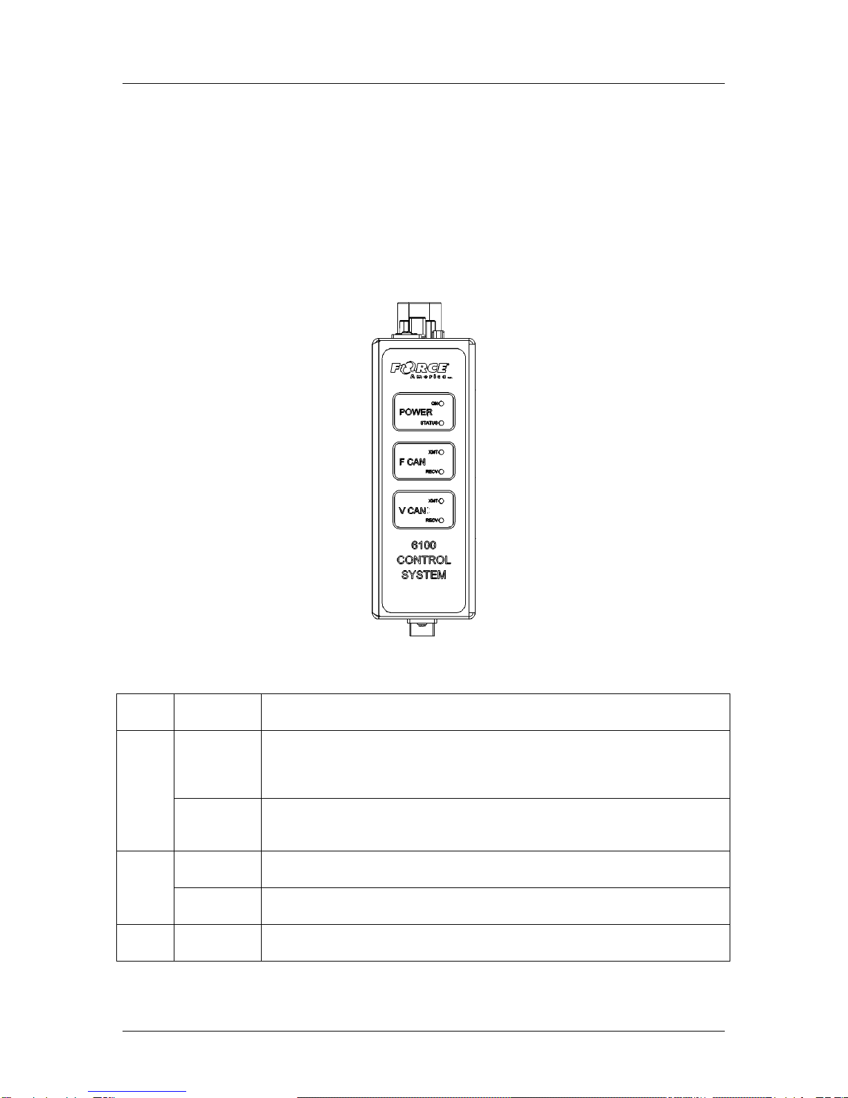
Core Module (PN: 1104694)
The Core Module is the heart of the SSC6100 system. It acts as the central point of
communication for all CAN devices, processing all the inputs and redirecting them to the
appropriate outputs.
The Core Module is mounted vertically on the floor of the vehicle. Its LEDs face up towards the
driver to present status information.
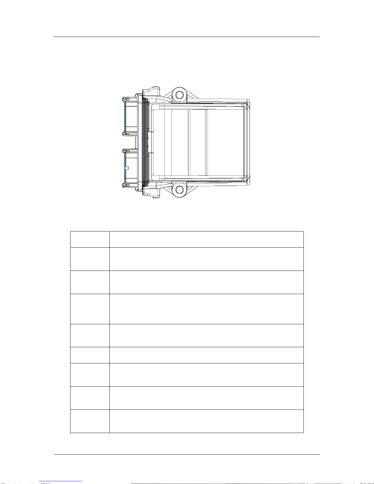
The top of the Core Module has 6 status LEDs, as shown in Figure 1:
Figure 1: Top of the Core Module
Label
LED
Function
Power
On
This LED displays the presence of the vehicle’s ignition switch. This LED
is lit when the vehicle’s ignition switch is in the powered position and is
unlit when it is off.
Status
This LED confirms the operating status of the SSC6100 hardware. This
light should blink if the SSC6100 hardware initialized successfully.
FCAN
XMT
This LED blinks when the Core Module transmits data on the CAN bus.
RECV
This LED blinks when the Core Module receives data from the CAN bus.
VCAN
XMT
This LED blinks when the Core Module transmits data on the CAN bus.

SSC6100 Operation Manual
Hardware
5
Label
LED
Function
RECV
This LED blinks when the Core Module receives data from the CAN bus.
The front of the Core Module has a single USB port, which can be used to import and export
calibration files or material usage reports. The ports on the back of the core module are used as
connectors to the Operator Interface, 20 Port Valve Module, 10 Port Valve Module, LCD Display,
and temperature sensor.
Do not attempt to connect the DVI connector
on the Core Module to any other device
besides a Force America 7 Inch LCD Display.
You may damage your equipment.
For more information on the ports on the back
of the Core Module, refer to the installation
drawing included in the SSC6100 Binder.
SSC6100 Operation Manual
Hardware
6
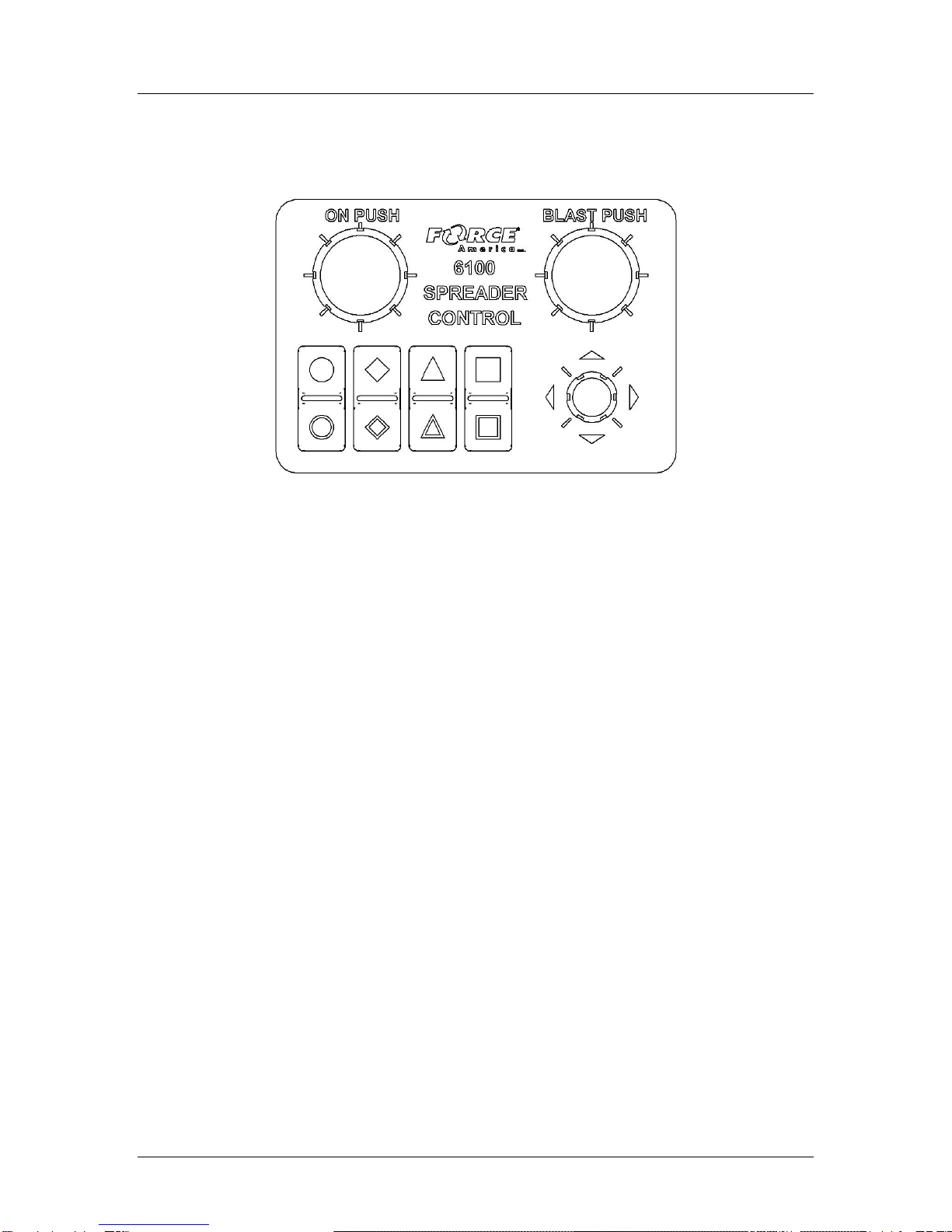
Operator Interface (PN: 1104696)
The Operator Interface lets you control all the aspects of the SSC6100.
Figure 2: Operator Interface
The Operator Interface has two single-axis encoders, one triple-axis encoder, and eight “soft
switches” that act as pushbuttons for SSC6100 functions. The functions that they control change
depending on what portion of the SSC6100 system is active. See System Operation on page 18.
SSC6100 Operation Manual
Hardware
7
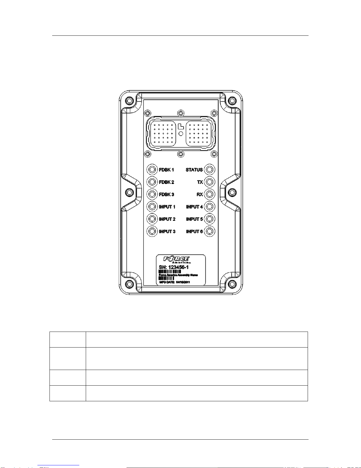
20 Port Valve Module (PN: 1018887)
The 20 Port Valve Module acts as the primary driver of outputs for an SSC6100 system. It
contains a 50 pin Deutsch connector with a harness for feedback inputs to the Core Module, as
well as LEDs to inform you of the Valve Module’s operational status.
Figure 3: 20 Port Valve Module
LED
Function
STATUS
This LED displays the presence of CAN power to the valve module. This LED
blinks when the valve module is powered and is unlit when it is not.
TX
This LED blinks when the Valve Module transmits data on the CAN bus.
RX
This LED blinks when the Valve Module receives data from the CAN bus.

SSC6100 Operation Manual
Hardware
8
LED
Function
INPUT 1
The INPUT 1 LED will light when the valve module detects a grounding signal
from a connected sensor. In many systems, this is connected to a Low Filter
Bypass sensor.
INPUT 2
The INPUT 2 LED will light when the valve module detects a grounding signal
from a connected sensor. In many systems, this is connected to a High Filter
Bypass sensor.
INPUT 3
The INPUT 3 LED will light when the valve module detects a grounding signal
from a connected sensor. In many systems, this is connected to an Oil Level
sensor.
INPUT 4
The INPUT 4 LED will light when the valve module detects a grounding signal
from a connected sensor. In many systems, this is connected to an Oil
Temperature sensor.
INPUT 5
The INPUT 5 LED will light when the valve module detects a grounding signal
from a connected sensor. In many systems, this is connected to a Body Up
sensor.
INPUT 6
The INPUT 6 LED will light when the valve module detects a sourcing signal from
a connected sensor.
FDBK 1
The FDBK 1 LED will flash when the Valve Module receives pulses from a
connected feedback sensor. In many systems, this feedback input is connected to
Auger / Conveyor Feedback.
FDBK 2
The FDBK 2 LED will flash when the Valve Module receives pulses from a
connected feedback sensor. In many systems, this feedback input is connected to
Prewet Feedback.
FDBK 3
The FDBK 3 LED will flash when the Valve Module receives pulses from a
connected feedback sensor. In many systems, this feedback input is connected to
Direct or Spinner Feedback.

SSC6100 Operation Manual
Hardware
9
10 Port Valve Module (PN: 1101182)
The 10 Port Valve Module acts as the primary driver of outputs for an SSC6100 system. It
contains a 50 pin Deutsch connector with a harness for feedback inputs to the Core Module, as
well as LEDs to inform you of the Valve Module’s operational status.
Figure 4: 10 Port Valve Module
LED
Function
STATUS
This LED displays the presence of CAN power to the valve module. This LED
blinks when the valve module is powered and is unlit when it is not.
TX
This LED blinks when the Valve Module transmits data on the CAN bus.
RX
This LED blinks when the Valve Module receives data from the CAN bus.

SSC6100 Operation Manual
Hardware
10
LED
Function
INPUT 1
The INPUT 1 LED will light when the valve module detects a grounding signal
from a connected sensor. In many systems, this is connected to a Low Filter
Bypass sensor.
INPUT 2
The INPUT 2 LED will light when the valve module detects a grounding signal
from a connected sensor. In many systems, this is connected to a High Filter
Bypass sensor.
INPUT 3
The INPUT 3 LED will light when the valve module detects a grounding signal
from a connected sensor. In many systems, this is connected to an Oil Level
sensor.
INPUT 4
The INPUT 4 LED will light when the valve module detects a grounding signal
from a connected sensor. In many systems, this is connected to an Oil
Temperature sensor.
INPUT 5
The INPUT 5 LED will light when the valve module detects a grounding signal
from a connected sensor. In many systems, this is connected to a Body Up
sensor.
INPUT 6
The INPUT 6 LED will light when the valve module detects a sourcing signal from
a connected sensor.
FDBK 1
The FDBK 1 LED will flash when the Valve Module receives pulses from a
connected feedback sensor. In many systems, this feedback input is connected to
Auger / Conveyor Feedback.
FDBK 2
The FDBK 2 LED will flash when the Valve Module receives pulses from a
connected feedback sensor. In many systems, this feedback input is connected to
Prewet Feedback.
FDBK 3
The FDBK 3 LED will flash when the Valve Module receives pulses from a
connected feedback sensor. In many systems, this feedback input is connected to
Direct or Spinner Feedback.
SSC6100 Operation Manual
Hardware
11
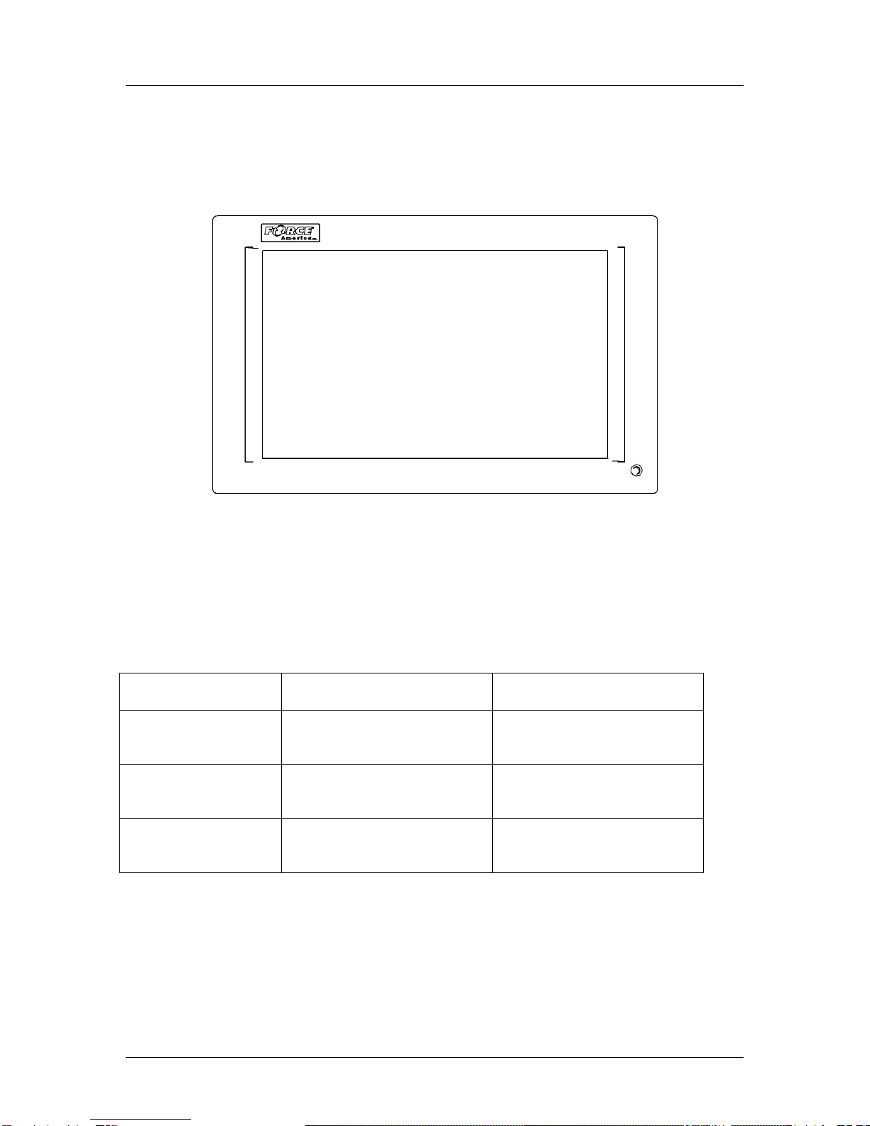
7-Inch LCD Display (PN: 1104695)
The LCD Display shows all of the interactive content, including operation status, configuration
options, material usage reports, and error codes.
Figure 5: LCD Display
The LCD has a bi-color LED which can light up green or red. It also has a buzzer to signal system
startup, system shutdown, or an operational error.
The following table describes the LED and buzzer states during startup, shutdown, and while the
system is running.
Status
During Startup & Shutdown
System Running
LED: Solid Green
Buzzer: Silent
--
Normal Operation
LED: Blinking Red
Buzzer: Beeps Once
Normal Operation
CAN Communication Error
LED: Off
Buzzer: Silent
No Power to LCD
No Power to LCD

SSC6100 Operation Manual
Hardware
12
6100 Event Logging Authentication Module (PN: 1016063)
The 6100 Event Logging Authentication Module, 6100 ELA Module, is an optional component for
the SSC6100 that configures the system to use AVL Event Logging. It provides security
information and your unique group ID to the spreader control so that it can communicate with the
AVL module.
Figure 6: 6100 Event Logging Authentication Module
If Event Logging is set to AVL in Calibration, you will see the DGID item in the Version Menu. It
will display your Digital Group ID code, a unique identifier for your operation and AVL provider,
which can be used to re-order 6100 ELA Modules.
If the 6100 ELA module is disconnected but is required by the system, an Event Logging
Authentication Module Communication Error will appear. See Troubleshooting and Error
Conditions on page 116 for more information.
SSC6100 Operation Manual
Hardware
13
Direct Liquid Application Module (PN: 1018830)
The Direct Liquid Application (DLA) Module runs the main direct liquid pump and lane ball valves,
and receives feedback from direct sensors.
Figure 7: Direct Liquid Application Module
The DLA Module has LEDs to inform you of the input and output states.
LED Label
Function
TX
The TX LED blinks when the DLA Module transmits data on the CAN
bus.
RX
The RX LED blinks when the DLA Module receives data from the
CAN bus.
Status
The Status LED confirms the operating status of the DLA Module.
This light should blink regularly if the DLA Module initialized
successfully.
Input 1
The Input 1 LED will blink when the DLA Module receives pulses
from a connected feedback sensor.
Input 2
The Input 2 LED is reserved for future use.
Input 3
The Input 3 LED will be lit when the DLA Module receives a low
liquid warning from a low liquid sensor.
Out 1
The Out 1 LED will be lit when the DLA Module is running the main
direct valve via PWM.
Out 2
The Out 2 LED will be lit when the DLA Module is running the left
lane.

SSC6100 Operation Manual
Hardware
14
LED Label
Function
Out 3
The Out 3 LED will be lit when the DLA Module is running the center
lane.
Out 4
The Out 4 LED will be lit when the DLA Module is running the right
lane.
Out 5
The Out 5 LED is reserved for future use.

SSC6100 Operation Manual
Powering up the SSC6100
15
Powering up the SSC6100
Upon applying either remote or dashkey power to the SSC6100, the 1104695 LCD Display will
beep once and its status LED will illuminate orange or blink red. On the 1104694 Core Module,
the Power On and Power Status lights will be lit.
As the system boots, it will display the SSC6100 logo on-screen with a blue-on-gray progress bar
at the bottom. The progress bar will scroll from left to right as the system starts up. See Figure 8.
Figure 8: SSC6100 Boot Screen
After booting, the SSC6100 shall test the ESTOP wiring for faults. You will see the Testing
ESTOP… screen, shown in Figure 9.
Figure 9: Testing ESTOP… Window
After the ESTOP test, if no errors occurred, the system will return to normal operation. Joysticks
will be activated after the ESTOP test is complete.
If an ESTOP Miswired Error or a CAN Device ESTOP Miswired Error occurs, shut down the
vehicle and the spreader control, then follow the steps outlined in Troubleshooting and Error
Conditions on page 116.
When the SSC6100 has completed booting and testing ESTOP, it will display either the Spreader
Power Off Screen or the Operation Screen, depending on the status of the spreader power
switch. The status LED on the 1104695 LCD Display should be lit solid green.
If this system is configured to require a Driver ID, you may see this message on startup:

SSC6100 Operation Manual
Powering up the SSC6100
16
Figure 10: Driver ID Required Notice
Place the black Driver Key on the security port to login to the spreader control. Upon a
successful login a welcome message similar to the following message will be displayed. The
logged in Driver ID will replace the SAMPLE text.
Figure 11: Driver Logged In Notice
Press the Navigation Stick to acknowledge the login. The Driver ID will then be reported with all
event strings, if enabled, from the spreader control. If an unsuccessful attempt was made to
login to the spreader control an error message will appear on the screen. See Troubleshooting
and Error Conditions on page 116 for more information.
If this system is configured with an Adjustable Gate, you may see this message on startup:
Figure 12: Check Gate Setting Warning
Other manuals for SSC6100 CAN ULTRA
4
Table of contents
Other Force America Control System manuals


